1
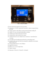
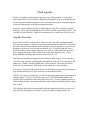
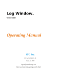
RC1-Y/RC1-H USER MANUAL MDS 2930 GA Hwy 33N Moultrie, GA 31768 [email protected] Copyright 2014, All Rights Reserved. Limited Warranty All MDS products are warranted for one year, parts and labor, for defects in parts and workmanship. This period starts from the time of product registration, or from the receipt provided by the dealership. All products purchased on the MDS website are automatically registered. This warranty does not cover surge, lightning, water or moisture damage, or physical abuse. The LCD is not warranted against scratches or punctures. MDS reserves the right to repair or replace defective products at our discretion. Specifications and ratings of the controller may change at any time without notice. RC1 FEATURES Direct replacement control box for Yaesu rotators Station power, 13-14VDC required for Yaesu and d.c. rotators, emergency/battery power OK Computer control via the USB port, starting with serial numbers ending 425 Graphic LCD screen with Large bright numbers and letters Automatic speed control on DC powered rotators Automatic brake control on Ham Series rotators Automatic direction reverse on Ham Series to ‘break loose’ a stuck brake (Rev 1.6 and up) Goto and Reciprocal heading button and knob for quick heading control Priced below the repair cost of the Yaesu control box, and half the cost of similar digital control boxes. Field upgradeable firmware via the USB port Rugged steel enclosure Made in U.S.A. at our Georgia facility Weight: 650 grams Dimensions: 85.7mm H x 133.4mm W x 104.8mm D QUICK USE GUIDE For the RC1-Y model, it is as simple as connecting your 13-14 volt DC station power supply to the supplied 2.1mm power cord, unplugging your old Yaesu control box, and plugging the cable into the new RC1-Y control box. For those who have older G-800/1000S or SDX models, they use a North stop system. Follow the instructions in the Menu section to invoke the North stop. Also, these older Yaesu rotors have a Jones-type plug on the control box. We have a limited number of the newer male plugs to change your rotor cable over (at extra cost). Pins 2,3,4 and 5 are all that are needed, and are wired Jones pin 2 to 2, pin 3 to 3, etc. Crimp the pins on #18 or #16 insulated wire then solder the crimp to make sure it will not come loose. The back of the white plug is numbered, and follows the old Jones-type plug numbering system. The RC1-G model supports the Yaesu models which use 24-28 volts a.c. power. You must supply this 24-28 volts a.c. at approximately 2.5 amps to the RC1 control box. You can purchase a power pack (wall wart) or use the power transformer from your old control box. One way to do this is the short out either the left or right switch on your old control box. Then, you will find that 24 volts will be present on pin 6 and either pin 4 or 5 on the rear connector (depending on which switch you shorted out inside your old control box). Orion 2800AC is same as RC1- G model except pins 2 & 3 are pulse inputs. You can run this power with the supplied power cord to power the RC1-G. For the RC1-H, the user must supply 24-28 volts a.c. at 5 amps. The quickest way to do this is the use your old rotor control box. Only the power transformer in the old Ham series box will be used. Simply remove bottom cover from your Ham series control box. Move one of the two wires from the center switch (brake switch) to the other wire on this switch. This will effectively cause the brake to be on all the time, providing 28 volts to pins 1 and 2 of the old control box connector or terminal strip (depending on your model). See the page and photos later in this manual on Ham series modification. For the older Ham series control boxes, the control box output for the rotor is a screw terminal strip. Included with the RC1-H is an 8-pin Jones plug with which you can upgrade your rotator cable to the new box style. Pin 1 goes to screw terminal 1, pin 2 to terminal 2, etc.. For the older series Ham control boxes, connect the included 2.5mm power cord to pins 1 and 2 of the old terminal strip. Ensure the barrel of the 2.5mm goes to pin 1 of the terminal strip, tip of the power plug to pin 2 of the terminal strip. For the new type Ham series, connect the power cord to pins 1(barrel) and 2 (tip) of the included Jones plug pins 1 and 2, and plug the new Jones plug into your new series Ham control box. After you modify the brake switch, you can use the power switch on the old Ham series control box to control the power on your RC1-H box. Orion 2800DC is the same as RC1-Y Yaesu except pins 2 and 3 go to the pulse input. Now that you have the rotor cables connected, and power to the box, you will see the graphic display come up with large center digits showing the current antenna position. To the lower right of the screen, you will see the current setting of the ‘GOTO’ control knob. Turn the GOTO knob and watch those digits change. To the lower left, you will see the ‘CMD’ heading. The CMD heading is the computer control heading. This can be either a command sent via the RS-232 port on the rear, or by pressing the goto button on the front panel. When you press the goto button, it transfers the GOTO heading into the CMD heading and starts turning your rotator. If you press and hold the goto button for several seconds, it will send a reciprocal (long path) heading of the knob’s heading. Remember, it does the reciprocal of the goto knob’s setting NOT the current position! In the upper right, you will see one of 8 cardinal directions, which shows you which direction you are closest to: N, NE, E, SE, S, SW, W, and NW. If you see the error message ‘CABLE’ on the screen, it means the RC1 box cannot see your rotor’s position pot. Normally, you forgot to plug in the rotator cable, made a mistake in wiring your new Jones plug (Ham series only), or your rotator pot is defective. NOTE: the heart of this control is the rotator’s position pot. If it is defective, the RC1 has no way of determining what to do. Although the left and right buttons will still move the rotor, no automatic features can be used. If your rotator is older, and your pot is noisy and intermittent, the RC1 will not be able to work correctly. On models with overlap, like the Yaesu series, you will see the message on the right-hand side that says ‘OVER’ when you are in the overlap area. The Yaesu’s will turn 450 degrees, while the Ham series will only turn 360 degrees. Once you have verified the control box is working by manually moving or using the goto feature, and you see the center digits change normally, you are ready for computer control. Hook up a serial cable to the back of the RC1 box. A normal, 9-pin straight through (non-null) cable, is required. Turn on the control box. Bring up any number of rotor control programs like LP_Rotor or use the rotor control feature in Ham Radio Deluxe. Follow the instructions with that program, and set up the proper com port and the RC1 uses the DCU1 protocol. There should not be a baud rate option, for all DCU1 uses 4800 baud N81 (no parity, eight data bits, one stop bit). DXView is another program that does automatic rotator control. Some of these programs require you to tap the cursor on a simulated rotator face, and some a world map. There are also some that can be set to automatically turn the rotator to the station appearing in a DX cluster! We have verified that the RC1 works well with any of the three programs mentioned above. A note about HRD version 5: this program will move the antenna but not provide azimuth feedback. HRD version 6 has been fixed. Please see the Menu and Customizing section for Advanced Features of the RC1, but, for now, it is pretty simple and powerful to use. NOTE: LP Rotor has a few bugs, which we have brought to the attention of the author. One annoying thing is that when first brought up you MUST have a COM1 in your computer somewhere before you can change the comm. port setting. This is also the case if you remove the comm. port you had previously used with LP Rotor. Another thing is if you disconnect the serial cable for some time, it will not refresh the position needle when plugged back in. You must restart the program. A Word about Position accuracy The RC1 will normally end up within about 5 degrees of the desired heading when using computer control or the Goto button. This depends a lot on the wind load, and size of your antenna array. If your ending azimuth is always exceeds your desired heading, you may wish to use the COAST feature to turn off the motor a little early. Most 3 or 4 element antennas have a large beamwidth of 50 degrees or more. With these antennas, being within half the beamwidth is plenty good enough accuracy. The RC1’s designer had 68 elements on UHF, and even with this array, 5 degrees was good enough! Menus and Customizing There are several menus available to customize your RC1 control box. The menu options are: Calibrate, Offset, Callsign, Defaults, Coast, Sleep, Northstop, and Brake (if equipped). To enter the menu system, press and hold the encoder shaft for several seconds. Turn the encoder shaft to change the entry value, and push the shaft (knob) to act as a select or enter key. Calibrate Although you can calibrate the rotator for optimum accuracy, you may find that it is quite accurate without calibrating. We have found the pots in all rotors tested to be quite accurate. Most of the time, what you might require is the Offset feature, because your rotor is off the same amount of degrees all the time. That problem is corrected with Offset, not Calibrate! To calibrate your RC1, first go into the Defaults menu and wipe out any and all modifications you have already entered. If you desire to recalibrate your rotator, the RC1 does this by the start and end of the potentiometer, or LEFT stop SOUTH and RIGHT stop. Depending on the model, RIGHT stop can 180 for HyGain models, and 270 in overlap for Yaesu models. (Pulse input for the Alpha, Orion AC and Orion DC just needs the current position of your antenna.) Or, run the antenna to the left stop for auto-calibrate. You must position the rotor to it’s left stop and right stop, and do NOT concern yourself with the antenna position right now. If the azimuth heading is not correct, you can use OFFSET to correct the azimuth. If your pot is off by a lot, for some reason, the RC1 will NOT accept the reading. Move the antenna first to the left stop until you see the antenna will no longer turn left. Do not use the display azimuth to determine if the antenna is as far left as it will go. Do a left stop calibrate. Similarly, move the rotor to the right stop and calibrate there. Now you can invoke some OFFSET to correct the azimuth on the display. Word of caution: it is possible that with a large offset required, that the hard stops of the rotor come into play. You may feel that the rotor ‘turns the wrong way’ on an automatic move. But that is possible with a large amount of offset put in. Callsign You may enter your callsign to customize YOUR RC1 controller. Select Callsign with the encoder knob. Then execute the callsign menu by pushing the encoder knob. Now rotate the goto knob and watch the first letter of your call appear on the lower screen. When that letter is correct, push the knob to move on to the next character or number. When finished push the knob with NO rotation. Northstop If you have an older Yaesu rotor where the mechanical stop is at North instead of South, you need this function. First, calibrate the rotor. Then select this menu and then hit the encoder knob to say Yes to North stop. Offset Most the time, this is the one thing most of us need to change. You might find the RC1 shows, for example, 120 degrees. If you go out and look and your antenna, and with a compass it is actually pointing 108 degrees. Well, then you need 108-120 offset of –12 degrees. Zero degrees using the goto knob means zero offset. 010 goto knob means +10 degrees. But, in the above example we need minus, and you can get minus degree by a reading to the left of zero degrees. In other words 350 is 10 degrees left of north (360 or zero degrees). So to get minus 12 we set the goto knob for 360-12 or 348 degrees. Then push the encoder knob. A few notes about offset…when setting an offset, do not forget about your hard stops (i.e. 181 degrees for the Ham series (left) and 180 degrees for the Yaesu (left)). So, you have ‘offset’ your display, let us say, 20 degrees plus. Well, the stop will now show up 20 degrees further at 201. Also, the rotor may seem to make wrong choices as to direction of turn, but it knows where the hard stops are, and will get you there. So, remember that using offset also ‘offsets’ your rotor stops and overlap areas as well. Defaults If you seriously mess up something in the menu system, you can undo all your mistakes by selecting the defaults menu and hitting the left button. This will wipe out any calibration, offset, and callsign you might have entered. The RC1 will restart after Defaults are invoked. Contrast Level The RC1 now has the ability to adjust the angle of view via an electronic contrast level. When you adjust the level with the encoder knob, the display adjusts instantly, showing you what you will get with the new setting. Press the encoder knob when you are satisfied with the display when done. Sleep Timer The RC1 has a default sleep timer of 10 minutes. At this time, with no button or RS-232 activity, the RC1 will go into a low power mode, clear the screen and shut off the lcd back light. Setting a time delay value of zero will disable the sleep mode. The numeric values are in minutes, up to 255 minutes. NOTE: some PC programs continuously poll the USB port. In these cases, the unit will never go to sleep. Shut down the PC program to disable the polling. Brake Delay Timer The RC1 has a default brake delay timer of 1.0 seconds. After the motor is stopped, the RC1 will time ‘brake delay number of seconds’ then turn off the brake solenoid, engaging the brake. This only applies to units with a brake. You may adjust the brake delay up to 5.0 seconds. If you also use the Coast feature, make sure your brake delay is long enough to allow your antenna to coast to that heading. Coast Setting The RC1 has the ability to add an antenna Coast setting. This setting is in degrees (up to 10) that will disengage the motor a few degrees early to allow your heading to be a little more accurate when the antenna comes to a stop. For Ham series users, make sure your brake delay is longer than it takes for the antenna to coast. Be mindful that when you are coming up against the rotors hard, mechanical stops, that this feature will not help. Also, when automatic GOTO or computer settings are invoked, changes less than 20 degrees will not use the coast setting. Reverse LCD The RC1 has the ability to reverse the pixels on the LCD screen. The normal or default look is white numbers on a blue background. By setting Reverse, you may see blue numbers on a white background, which could aid in viewing the screen if your vision is impaired. Flash upgrade The RC1 is capable of field program upgrade via its USB port input. You may have noticed that the RC1 seems to have a slight delay during power up. It is during this time that the built-in bootloader program is active, looking for the proper command sequence to begin a flash upgrade of the internal program memory. From time to time, MDS may make available updates to the RC1 control box internal firmware. These upgrade modified hex files will be available on the MDS website. You can ONLY use the mds file. Under no circumstances try to modify this file in any way. Upgrade Procedure Power down your RC1 controller box. Make sure the serial cable is plugged into the RC1 and your computer. Start the TeraTerm program included on the CD. Select Serial and your virtual com port number on the opening screen(You may have to go to Device Manager/Com Ports to see what com port number it is). Click the Setup tab. Select Serial Port. Make sure the proper com port is set, then set 9600 baud N81 (no parity, 8 bits, 1 stopbit) and none for flow control, and 30 into msec/line delay box. Select Setup/Terminal and change the Transmit from CR to CR + LF. Now find your downloaded upgrade hex file from the MDS website. In TeraTermPro select File, then Send File, and highlight the upgrade hex file, BUT do not click the OK button yet!! Within 4 seconds elapsed time, power up the RC1 box and click OK on TeraTerm file send window. This must be done within the 4 second window. You will see TeraTerm send the data, the RC1 will return a period to show each memory page written and then give a success message in its terminal window. If the RC1 just powers up normally, you did not make the upgrade power up within the 4 second window. If you see an error message in the TeraTerm terminal window, you probably did not set the msec/line delay that is necessary. If you see random characters in the terminal window, you probably did not set the baud rate to 9600 baud N81 with no flow control. If all else fails, and you feel uncomfortable with this upgrade procedure, you may send your unit back for upgrade at no charge except you must pay shipping both ways. DCU1 Protocol The DCU1 protocol is one of the most popular control protocols for antenna rotators. It allows the control and monitoring of your rotator via packets of commands send to your computer’s serial port. Normally, these commands are part of a separate program like LP_Rotor, but also can be built into more complex programs like Ham Radio Deluxe, or DXView. There are three command frames and one character command: "AM1;" which means start turning “AP1xxx” which means the new heading is xxx “AI1;” which means send me your current position “;” which means stop the rotor NOTE: Some programs do not use the full DCU1 protocol. There are some programs which expect the rotor to turn by ONLY sending the AP1xxx command. The RC1 needs both the AP1 and the AM1 commands to begin movement. Error Messages There are two error messages shown on the screen: CABLE, and MOTOR. CABLE means that the cpu chip is unable to read the pot inside your rotor. For older rotors, this means the pot is dirty or corroded and intermittent. You can verify this moving the rotor with the left or right button and see if the message goes away and the main position digits start moving again. Another cause of the message CABLE could be a bad connection either at the rotor or control box end. Your pot is most likely 500 ohms maximum, down to near zero ohms. For Yaesu rotors measure between pins 2 and 3. For the Ham series, measure between pins 1 and 3 on your rotor cable connector. The MOTOR message means that the cpu has not detected enough movement of your rotator motor in a specific amount of time. This could be caused by high winds or a cable has caught, or the mast is slipping in the rotor mast clamp. Alternatively, this message could also indicate an open circuit in the motor wiring. For the Yaesu this is pins 4 and 5. For the Ham series you have the complication of several factors: motor, brake, and motor capacitor. For the Ham series, pins 1 and 2 control the brake: 24 v.a.c. supplied releases the brake, pins 4 and 8 are the motor capacitor, pin 5 motor right, and pin 6 motor left. LEFT STOP and RIGHT STOP messages (Version 1.4 and above) tell you that you have hit the left or right mechanical stops in your rotor. Ham Series Modification If you have ever soldered wires at all, this modification is quick and easy. Please refer to Photo 1 below. Remove the bottom cover of your Ham series control box. Find the two wires going to the center brake switch. Remove one of the wires and solder (short) it out to the other wire on that switch. In the photo, the green wire was moved to the black wire. Replace the cover. If you have a new series Ham rotor, you have a Jones plug (8 pin rectangular) socket on the rear of your control box. In this case, take the new Jones plug supplied with your RC1-H and your included power cord, and connect the cord to pins 1 and 2. Pin 1 should go to the barrel side of the coax plug and pin 2 to the tip. If you have an older Ham series with a terminal strip. Mark the wire numbers on your rotor cable then remove your rotor cable from the old control box. Wire them up pin 1 to 1, pin 2 to 2, pin 3 to 3, etc. to the new Jones plug. Take the two ring terminals and solder or crimp them to the ends of the included power cord. . Pin 1 should go to the barrel side of the coax plug and pin 2 to the tip. Now you can use your old control box’s power switch as a power switch for your new RC1-H. Photo 1. Theory of Operation Your RC1 control box uses some of the latest in microcontroller technology. A microcontroller differs from a microprocessor in that microcontroller has everything it needs built into it, like program memory, ram, analog-to-digital converters, timers, eeprom to store permanent values, input/output ports, and many other features. This Atmel ATMEGA32U4 microcontroller is capable of near 8 million operations per second, so, most of time, it can hardly find anything to do! External to the mega32U4 chip is an ttl serial to USB converter chip which allows your computer send commands and read positions from the RC1. The analog-to-digital converter reads the pot on your rotor 10 times per second. Then it uses a process called digital signal processing (DSP) to noise filter, and average those readings to produce to the firmware a smooth reading. But still, with an unusually dirty pot, no amount of filtering will help. If your pot goes from, say, 200 ohms to infinity (open), the dsp cannot recover from dozens of infinity readings, but CAN recover from a few bad readings easily. The pot reading is the heart of the RC1 control. We must have feedback from the rotor to control it properly. . Power relays controlled by output lines from the Mega32U4 control your rotor motor. In the case of d.c. rotor motors like the Yaesu and Emotator, there is a power relay and a direction relay. In the case of the Ham series or a.c. rotators, there are three relays, one for the brake and power, one for left, and one for right. Control is more complicated for the Yaesu and d.c. rotor motors. The RC1 has built-in circuitry for producing the 12 to 28 volts d.c. the motor requires. When the turning requirement is small, under 30 degrees, the RC1-Y will produce low voltage (12) only. When more than 30 degrees, the voltage ramps up quickly from 12 to 28, then, when approaching the target heading, slows down again by ramping down the voltage. One of the more complicated tasks the RC1 has to do is to show you, the user, what is happening, on the LCD screen. This is a bit-mapped graphic screen of 128 by 64 pixels with white led backlight. All the characters on the LCD are formed by writing streams of pixels, not characters, to the screen. The RC1 could be adapted for other character sets like Chinese or Japanese.