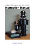
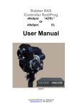
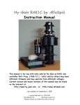
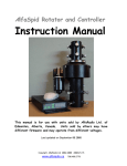
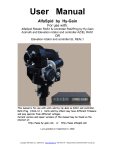
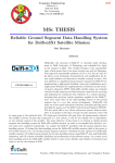
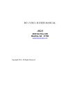
1
 AlfaSpid MD-01 Controller
11211 - 154 St.
Edmonton, Alberta, Canada T5M 1X8
[email protected]
780 466 5779
www.alfaradio.ca
Revised 15March2013
http://www.alfaradio.ca
This manual is for use with units sold by Alfa Radio Ltd. of
Edmonton, Alberta, Canada.
Units sold by others may have
different firmware and may operate from different voltages.
Page
1 of 20
file ~alfaspid/md-01/AlfaSpid_MD-01_Operation_15April2013_Master.doc April 15, 2013
11211 - 154 St.
Edmonton, Alberta, Canada T5M 1X8 [email protected]
780 466 5779
www.alfaradio.ca
Table of contents
Table of contents ................................................................ 2
Introduction.................................... .................................4
Block diagram .................................................................... 4
Photos and description ........................................................... 5
Front .......................................................................... 5
Back ........................................................................... 6
Operation ........................................................................ 8
Normal mode (NORMAL) ........................................................... 8
Calibration mode (MOTOR ANGLES) ................................................ 9
Controller MD-01 configuration .................................................. 10
Motor configuration ........................................................... 10
TEMPLATE .................................................................... 10
Show Azimuth ................................................................ 10
Short Way ................................................................... 11
USE EL MAP .................................................................. 11
Const EL MAP ................................................................ 11
Start ....................................................................... 12
Stop ........................................................................ 12
Mouse Control ............................................................... 12
External control (CONTROL xx) ............................................... 13
Protocol (PROT. xx) ......................................................... 14
Page
2 of 20
file ~alfaspid/md-01/AlfaSpid_MD-01_Operation_15April2013_Master.doc April 15, 2013
11211 - 154 St.
Edmonton, Alberta, Canada T5M 1X8 [email protected]
780 466 5779
www.alfaradio.ca
PAIR ........................................................................ 14
Set motors (SET MOTOR 1, SET MOTOR 2) ......................................... 14
STATE ....................................................................... 14
TYPE ........................................................................ 14
KIND ........................................................................ 14
INPUT ....................................................................... 14
GEAR ........................................................................ 15
MIN ANGLE ................................................................... 15
MAX ANGLE ................................................................... 15
MAX POWER ................................................................... 15
START POWER, START TIME ..................................................... 15
STOP POWER, STOP TIME ....................................................... 18
STOP AT ..................................................................... 18
PULS TIMEOUT ................................................................ 18
SET COM 0, SET COM 1 .......................................................... 18
STATE ....................................................................... 18
BAUD ........................................................................ 18
DATA BITS ................................................................... 18
STOP BITS ................................................................... 18
PARITY ...................................................................... 18
SET USB COM ................................................................... 19
STATE ....................................................................... 19
BAUD ........................................................................ 19
SET ETHERNET – with optional module ......................................... 19
STATE ....................................................................... 19
WARRANTY
Page
3 of 20
................ 20
file ~alfaspid/md-01/AlfaSpid_MD-01_Operation_15April2013_Master.doc April 15, 2013
11211 - 154 St.
Edmonton, Alberta, Canada T5M 1X8 [email protected]
780 466 5779
www.alfaradio.ca
Introduction
MD-01 is an electronic Controller used for turning rotators.
It is a
multifunction device, allowing for various combinations of settings.
The Controller may be connected to two single rotators (e.g. two
Azimuth rotators) or (one Azimuth and Elevation rotator).
The
Controller operates with direct current motors.
Block diagram
Page
4 of 20
file ~alfaspid/md-01/AlfaSpid_MD-01_Operation_15April2013_Master.doc April 15, 2013
11211 - 154 St.
Edmonton, Alberta, Canada T5M 1X8 [email protected]
780 466 5779
www.alfaradio.ca
Parameters of the MD-01 Controller
• supply voltage for Controller Electronics 12 to 15 VDC (Imax = 2
Ampere)
• supply voltage for rotators 12 to 24 VDC (Imax = 40 Ampere),
• the maximum current of a single motor is up to 20 Ampere.
• 2 x RS-232 ports
• 1 x USB host port
• 1 x USB device – visible in the system as the virtual COM port.
• 1 x Ethernet RJ45 port.
Photos and description
Front
1. Keyboard.
2. 2x20 characters display.
3. Switch-key.
Page
5 of 20
file ~alfaspid/md-01/AlfaSpid_MD-01_Operation_15April2013_Master.doc April 15, 2013
11211 - 154 St.
Edmonton, Alberta, Canada T5M 1X8 [email protected]
780 466 5779
www.alfaradio.ca
Back
1.
Plug-in socket for Ground Connection (the remaining PINs are NC).
2.
Rotator motor supply input (FUSE at 40 Ampere Max).
3.
N/C, in the future, planned for connecting modules, e.g.- CAN, RS485, RS-422 or analogue inputs.
4.
Sensor Input for systems with one or two HALL effect type sensors.
5.
Power Supply input for Controller Electronics (FUSE 2A).
6.
Supply outputs for Elevation Rotator.
PINs 1 and 2 are connected to
the Rotator motor and PINs 3 and 4 are connected to the mechanical
sensor on RAU, RAK, Real and RAS rotators. The Motor output is FUSED
at 20 Ampere max depending on motor..
7.
Supply outputs for Azimuth Rotator.
PINs 1 and 2 are connected to
the Rotator motor and PINs 3 and 4 are connected to the mechanical
sensor in RAU, RAK, Real and RAS rotators.
The Motor output is FUSED
at 20 Ampere max depending on motor.
8.
Switch used to update the controller software (FIRMWARE).
To update
the software use COM 0 (item 12), with the switch in the OFF
position.
Normal mode of the controller is when the switch is in the
PR position.
9.
Universal output – Future use to connect external relays.
When
implemented, the controller will have the function of an antenna
change-over switch.
10.
I2C output – used to control SW-01 switch.
11.
USB HOST port (type A plug) and DEVICE port (type B plug).
12.
RS-232 ports – COM 0 and COM 1.
COM 0 is also used to update the
controller software (see item 8).
13.
Input used for a specially designed (RAS) mouse.
14.
Network input RJ45 (ETHERNET). Page
6 of 20
file ~alfaspid/md-01/AlfaSpid_MD-01_Operation_15April2013_Master.doc April 15, 2013
11211 - 154 St.
Edmonton, Alberta, Canada T5M 1X8 [email protected]
780 466 5779
www.alfaradio.ca
CONNECTOR PIN LAYOUT
Page
7 of 20
file ~alfaspid/md-01/AlfaSpid_MD-01_Operation_15April2013_Master.doc April 15, 2013
11211 - 154 St.
Edmonton, Alberta, Canada T5M 1X8 [email protected]
780 466 5779
www.alfaradio.ca
Operation
MD-01 Controller may be operated from the front panel keyboard or a
computer connected to one of the Communication ports.
MD-01 Controller has two modes (MODE).
•
NORMAL – normal mode.
•
MOTOR ANGLES – calibration mode.
To change the mode, use the [F] key.
Normal mode (NORMAL)
In this mode, the Controller may be operated with the [Right], [Left], [Up]
and [Down] buttons or receive commands from a Computer.
The Controller
supports communications protocols such as SPID ROT1, SPID ROT2, and YAESU
which can be assigned to any communications port (COM 0, COM 1, USB D and
ETH) in the settings.
YAESU mode may not support the full capability of
AlfaSpid rotators.
The [Right] and [Left] buttons are used to rotate the antenna in the
azimuth.
The right direction – the antenna turns in a clockwise direction, the value
of the angle in the display increases.
The left direction – the antenna turns in an anticlockwise direction, the
value of the angle in the display decreases.
The [Up] and [Down] buttons are used to rotate the antenna in the
elevation.
The up direction – the rotator turns right from the point of view of the
front.
The value of the angle in the display increases.
The down direction – the rotator turns left from the point of view of the
front.
The value of the angle in the display decreases.
The directions of antenna rotation are shown in the picture:
Page
8 of 20
file ~alfaspid/md-01/AlfaSpid_MD-01_Operation_15April2013_Master.doc April 15, 2013
11211 - 154 St.
Edmonton, Alberta, Canada T5M 1X8 [email protected]
780 466 5779
www.alfaradio.ca
Calibration mode (MOTOR ANGLES)
To switch the controller to the calibration mode, use the [F] button.
In this mode you can set the azimuth and elevation angles without
turning the antenna.
This mode is needed to preset and calibrate the
antenna positions.
To set the azimuth angle to zero, push the [F1] and [Left] buttons
simultaneously.
To set the elevation angle to zero, push the [F1]
and [Down] buttons simultaneously.
To set any azimuth angle use the buttons [Left] and [Right].
To change the elevation angle use the buttons [Up] and [Down].
After completing the calibration you need to leave the calibration
mode and come back to the normal mode by pushing the [F] button.
Page
9 of 20
file ~alfaspid/md-01/AlfaSpid_MD-01_Operation_15April2013_Master.doc April 15, 2013
11211 - 154 St.
Edmonton, Alberta, Canada T5M 1X8 [email protected]
780 466 5779
www.alfaradio.ca
Controller MD-01 configuration
When MD-01 Controller is in NORMAL mode you can use [S] button to
enter configuration mode.
The structure of the controller configuration mode is modular.
Select modules using buttons [Left] or [Right].
When you select a
module, you can use [S] button to enter in its parameters.
Moving
between parameters is done with the [Left] or [Right] buttons.
The
value of the parameter can change with the [Up] or [Down] buttons.
The [F] button is used for exiting the configuration mode.
After
pushing the [F] button there is a question about writing current
configuration into memory.
button.
To confirm the changes, press the [Left]
To go back to previous configuration press the [Right]
button.
Motor configuration
The number before the ":" in the name of the template determines
which connector on the rear panel the motor must be connected:
•
1.
AZIMUTH
2.
ELEVATION
TEMPLATE
The type of motors connected to the controller is pre-set by templates:
• 1:NC, 2:NC - no motors connected to the controller,
• 1:AZ, 2:NC - a motor is connected on the rear panel of controller on
connector AZIMUTH.
Motor rotates only in azimuth,
• 1:NC, 2:EL - a motor is connected on the rear panel of controller on
connector ELEVATION.
Motor rotates only in elevation,
• 1:AZ, 2:EL - there are two motors connected to the controller.
Motor
1 (connector AZIMUTH) rotates in azimuth, and Motor 2 (connector
ELEVATION) rotates in elevation,
• 1:AZ, 2:AZ - there are two motors connected to the controller, which
is rotated in azimuth only.
Page
10 of 20
11211 - 154 St.
file ~alfaspid/md-01/AlfaSpid_MD-01_Operation_15April2013_Master.doc April 15, 2013
Edmonton, Alberta, Canada T5M 1X8 [email protected]
780 466 5779
www.alfaradio.ca
Show Azimuth
Azimuth angle display format.
This angle can assume any value from -180 degree to 540 degrees max or
within the range of the rotator as set with the MAX and MIN Angle
settings for each motor.
•
MATH – show angle – from -180 degree to 540 degree,
•
NORMAL – show angle in 0 – 359 degrees.
•
Example:
MATH ANGLE
SHOWN ON DISPLAY
-1 degree
-359 degree
-2 degree
-358 degree
-179 degree
-181 degree
-180 degree
-180 degree
360 degree
+0 degree
361 degree
+1 degree
539 degree
+179 degree
540 degree
+180 degree
Short Way
OFF - Disable Shortest Route feature on AZ Rotators or the azimuth
portion of an AZEL Rotator
ON
- Enables Shortest Route feature on AZ Rotators or the azimuth
portion of an AZEL Rotator
USE EL MAP
Use elevation map.
azimuth angles.
This is a map of minimum elevation angles at specific
This map can be created with the program “spidMD01dde”
(name may change).
The map can be used when, for example, high
buildings or trees are around the antenna and obscure visibility.
Example: if USE EL. MAP is set (ON) and you set a minimum elevation angle
of 20 degree for azimuth angles from 10 degrees to 100 degrees, and a
Page
11 of 20
11211 - 154 St.
file ~alfaspid/md-01/AlfaSpid_MD-01_Operation_15April2013_Master.doc April 15, 2013
Edmonton, Alberta, Canada T5M 1X8 [email protected]
780 466 5779
www.alfaradio.ca
satellite tracking program, like Orbitron sends the MD-01 an elevation
angle less than 20 degree for an azimuth angle in 10 to 100 degree
range the MD-01 will only take the elevation angle to 20 degree.
The Elevation map is ignored when the MD-01 is controlling manually.
Note: ANGEL MIN and MAX ANGLE in SET MOTOR 1 (SET MOTOR 2) have a higher
priority than the angles of elevation map.
The rotator will not go
beyond these limits.
Const EL MAP
If this option is set to ON, option USE EL. MAP is ignored. And a
minimum elevation angle of 0 degrees azimuth is set for all Azimuth
angles.
This option is ignored when MD-01 is controlling manually.
Note: ANGEL MIN and MAX ANGLE in SET MOTOR 1 (SET MOTOR 2) have a higher
priority than the angles of elevation map.
The rotator will not go
beyond these limits.
Start
Motors run mode:
This is set for each motor separately in modules SET MOTOR 1 and SET
MOTOR 2, as described later,
•
IMMEDIATELY - motor starts with max speed, Soft start not active.
•
SOFTLY – so-called soft start
Stop
Motors stop mode:
This is set for each motor separately in modules SET MOTOR 1 and SET
MOTOR 2, as described later,
• IMMEDIATELY – at once,
Soft stop not active.
• SOFTLY – so-called soft stop
Page
12 of 20
11211 - 154 St.
file ~alfaspid/md-01/AlfaSpid_MD-01_Operation_15April2013_Master.doc April 15, 2013
Edmonton, Alberta, Canada T5M 1X8 [email protected]
780 466 5779
www.alfaradio.ca
Mouse Control
If you have a specially designed mouse by SPID (RAS Mouse), you can connect
it to the MD-01 controller on OUT3 port (13 in back picture of MD01).
The mouse works if you set this option to ON.
External control (CONTROL xx)
This parameter specifies the communication port that is used to
control the connected motors.
This parameter is not available when
template 1: NC, 2: NC is chosen.
If template 1: AZ, 2: AZ, is chosen, the motor can be controlled from
either of two ports.
The Controller display will show one or two descriptions depending on
the selected motor template:
• CONTROL A1 – motor template 1:AZ, 2:NC or 1:AZ, 2:AZ,
• CONTROL E2 – motor template 1:NC, 2:EL,
• CONTROL AE – motor template 1:AZ, 1:EL,
• CONTROL A2 – motor template 1:AZ, 2:AZ.
CONTROL parameter value:
•
NONE - no external control.
Motor controlled manually with buttons
on the controller,
•
COM 0 - external control with selected protocol.
Can also be
controlled manually,
•
COM 1 - external control with selected protocol.
Can also be
controlled manually,
•
USB - controlled through USB D with selected protocol.
Can also be
controlled manually,
•
ETH - controlled through ETHERNET with selected protocol.
Can also
be controlled manually.
Page
13 of 20
11211 - 154 St.
file ~alfaspid/md-01/AlfaSpid_MD-01_Operation_15April2013_Master.doc April 15, 2013
Edmonton, Alberta, Canada T5M 1X8 [email protected]
780 466 5779
www.alfaradio.ca
Protocol (PROT.
xx)
Communication protocol available between the controller and the control
device (for example, a PC program):
SPID ROT1 - Standard communication for all AlfaSpid rotators and
•
controllers in Azimuth mode
SPID ROT2 - Standard communication for all AlfaSpid rotators and
•
controllers in Elevation / Azimuth mode
YAESU - YAESU mode may not support the full capability of AlfaSpid
•
rotators.
•
SPID MD-01 - Future.
•
BRITE - Future.
New communication protocol from SPID Elektronik
New protocol created by SPID Elektronik firm and
Space Analysis Center in Warsaw.
•
HyGain - Future.
•
Future protocols are not guaranteed to be developed.
PAIR
Only when the selected template is 1: AZ; 2: AZ and the MD-01 is
controlled from an external program.
When the MD-01 receives an
azimuth angle from the program, both rotors will go to this angle.
Set motors (SET MOTOR 1, SET MOTOR 2)
•
STATE
Read only.
Depends on the TEMPLATE selected (see Motor configuration
-> TEMPLATE).
It displays whether the motor is switched on or
switched off.
•
TYPE
Type of motor return signal:
•
DIGITAL – controller counts pulses,
•
ANALOG – in the future.
Controller measures the voltage.
KIND
Read only.
Depends on the TEMPLATE selected (see Motor configuration
-> TEMPLATE):
Page
14 of 20
11211 - 154 St.
file ~alfaspid/md-01/AlfaSpid_MD-01_Operation_15April2013_Master.doc April 15, 2013
Edmonton, Alberta, Canada T5M 1X8 [email protected]
780 466 5779
www.alfaradio.ca
•
AZIMUTH – motor rotates in azimuth,
•
ELEVATION – motor rotates in elevation.
INPUT
Sensor type of controller MD-01 (only when the input type is
DIGITAL):
•
ELECTRONIC – rotator using electronic motion sensors (HALL
Effect),
•
MECHANIC - rotator using mechanical switches.
GEAR
Gear ratio of the rotator motor.
Example 0.0937 for RAS/HR, 1.0000
for RAU and 0.5000 for BIG-RAK
MIN ANGLE
Minimum angle, it is possible to limit turning for the motor.
Default -180
MAX ANGLE
Maximum angle, it is possible to limit turning for the motor.
Default +180
MAX POWER
Maximum power as a percentage of full power, which the controller
can provide to the rotator motor.
START POWER, START TIME
Used if you want to obtain a so-called “soft-start”.
You can set a
one, two or three-stage motor start
(START POWER 1, POWER START 2, and START POWER 3)
Power is expressed as a percentage of full power.
(START TIME 1, START TIME 2 and START TIME 3)
START TIME is expressed in seconds.
Page
15 of 20
11211 - 154 St.
file ~alfaspid/md-01/AlfaSpid_MD-01_Operation_15April2013_Master.doc April 15, 2013
Edmonton, Alberta, Canada T5M 1X8 [email protected]
780 466 5779
www.alfaradio.ca
Example: One-step
Set the initial speed of rotation of the motor
START POWER 1 = 30%.
Set the time to reach maximum power (MAX POWER)
START TIME 1 = 5 seconds.
In this example set START TIME 2 = 0 seconds. - doing this will
specify that the motor start is a single step.
Set MAX POWER to 100%.
This Example shows that the motor is started with 30% power, and
within five seconds linearly increases power to 100%.
Page
16 of 20
11211 - 154 St.
file ~alfaspid/md-01/AlfaSpid_MD-01_Operation_15April2013_Master.doc April 15, 2013
Edmonton, Alberta, Canada T5M 1X8 [email protected]
780 466 5779
www.alfaradio.ca
Example 2: three-step
•
Set the POWER START 1 = 20%
•
START POWER 2 = 30%,
•
START POWER 3 = 50%,
•
START TIME 1 = 3 seconds,
•
START TIME 2 = 3 seconds,
•
START TIME 3 = 3 seconds,
•
MAX POWER = 100%.
•
This means that the rotator starts with 20% power, within 3
seconds power reaches 30%, followed by 3 seconds power reaches
50% and last 3 seconds power up to 100%.
Page
17 of 20
11211 - 154 St.
file ~alfaspid/md-01/AlfaSpid_MD-01_Operation_15April2013_Master.doc April 15, 2013
Edmonton, Alberta, Canada T5M 1X8 [email protected]
780 466 5779
www.alfaradio.ca
STOP POWER, STOP TIME
Used, if you want to obtain a so-called “soft stop”.
It works the
same way as “soft start” except in the other way.
STOP AT
Specifies how many degrees before the specified angle (for example,
sent by a computer program like Orbitron) is to start the motor
stopping.
It only applies when Soft STOP is selected in MOTOR
CONFIGURATION.
PULSE TIMEOUT
Specifies how long the motor will run if it does not receive motion
pulses from the rotator.
Applies only to motors of type DIGITAL.
SET COM 0, SET COM 1
STATE
Read only.
Possible values: ON or OFF.
BAUD
Possible values: 600, 1200, 2400, 4800, 9600, 19200, 38400, 57600,
115200, 230400 and 460800.
DATA BITS
Possible values: 4,5,6,7 or 8 bit.
STOP BITS
Possible values: 1 or 2 bit.
PARITY
Possible values: none, odd or even.
Page
18 of 20
11211 - 154 St.
file ~alfaspid/md-01/AlfaSpid_MD-01_Operation_15April2013_Master.doc April 15, 2013
Edmonton, Alberta, Canada T5M 1X8 [email protected]
780 466 5779
www.alfaradio.ca
SET USB COM
STATE
Read only.
Possible values: ON or OFF.
BAUD
Possible values: 600, 1200, 2400, 4800, 9600, 19200, 38400, 57600,
115200, 230400 and 460800.
SET ETHERNET – with optional module
The Ethernet port is set for dynamic IP address.
Communication with
this port is done with the help of one of the protocols (SPID ROT1,
SPID ROT2, or Yaesu).
For example, the MD-01 controller receives the
IP address from a DHCP server (e.g. 192.168.0.10).
You can connect
to it, for example, Hyper Terminal by selecting the type of
connection TCP / IP (Winsock), set host address 192.168.0.10 and port
number to 23.
Protocol may be Yaesu, because it uses text protocol.
For testing only.
STATE
Read only.
Page
19 of 20
11211 - 154 St.
Possible values: ON or OFF.
file ~alfaspid/md-01/AlfaSpid_MD-01_Operation_15April2013_Master.doc April 15, 2013
Edmonton, Alberta, Canada T5M 1X8 [email protected]
780 466 5779
www.alfaradio.ca
12 MONTH LIMITED WARRANTY
AlfaSpid Rotators and controllers
Alfa Radio Ltd. Warrants to the user, who originally purchased the product, that the
product will be free from defects in material and workmanship for the following
periods after such date of purchase:
Material, 12 months : Workmanship, 12 months.
Alfa Radio Ltd. will, at its option, repair or replace free of charge such defective
products subject to the following conditions:
1. Delivery of the product prepaid to Alfa Radio Ltd. or its authorized dealer.
2. Determination by the Alfa Radio Ltd. that a defect exists and is covered by the
limited warranty.
Defects due to alteration, repair by an unauthorized person,
misuse, accidental damage, lightning strikes, use of the equipment for purpose
other than those for which it was designed, and the like, are NOT COVERED by this
limited warranty. Repairs therefore will be subject to normal service charges.
3. Repairs and replacement parts are covered under this limited warranty only for
the remaining term of the original limited warranty.
4. Under no circumstances is Alfa Radio Ltd. liable for consequential damages to
person(s) or property by the use of this product.
5. Alfa Radio Ltd. reserves the right to make changes or improvements in design or
manufacture without incurring any obligations to install such changes upon any of
the product previously manufactured.
6. All claims of defect or shortage should be sent prepaid to:
Alfa Radio Ltd.
11211 - 154 Street, Edmonton, Alberta,
T5M 1X8, CANADA
and must be accompanied by the letter describing the problem in
detail along with a copy of your proof-of-purchase.
Contact Alfa Radio Ltd. before sending.
Page
20 of 20
11211 - 154 St.
file ~alfaspid/md-01/AlfaSpid_MD-01_Operation_15April2013_Master.doc April 15, 2013
Edmonton, Alberta, Canada T5M 1X8 [email protected]
780 466 5779
www.alfaradio.ca