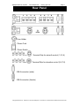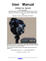
1
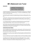
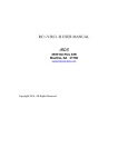
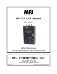
User Manual
AlfaSpid by Hy-Gain
For use with:
AlfaSpid Rotator RAS1 & Controller Rot2Prog by Hy-Gain
Azimuth and Elevation rotator and controller AZ/EL RAS1
OR
Elevation rotator and controller EL REAL1
This manual is for use with units sold by Hy-Gain as RAS1 and controller
Rot2-Prog ( RAS-1C ). Units sold by others may have different firmware
and may operate from different voltages.
Current version and newer versions of this manual may be found on the
internet at:
http://www.hy-gain.com or http://www.alfaspid.com
Last updated on September 5, 2008
Copyright Alfa Radio Ltd. 2008-09-05 www.alfaradio.ca 780 466 5779 Alfaspid-AZ-EL-2008-09-05-MFJ-manual.doc
AlfaSpid Rotator by Hy-Gain
www.alfaspid.com
www.hy-gain.com
Page 2
Table of contents
Introduction .................................................................................... 3
Shipping Contents.......................................................................... 3
Technical Data ............................................................................... 3
Control Panel ................................................................................. 4
Rear Panel ..................................................................................... 5
Installation ...................................................................................... 6
Wiring connections ..................................................................... 6
Bench Testing of Control Box..................................................... 7
Resetting the Controller ................................................................. 8
Controller Operation....................................................................... 9
Function Mode............................................................................ 9
Setup Mode (SETUP)............................................................... 10
Mouse Controller.......................................................................... 12
Please check with our web sites for information on firmware
updates, corrections, or changes to this information.
Updates may be found on
http://www.hy-gain.com or http://www.alfaspid.com
Copyright Alfa Radio Ltd. 2008-09-05 www.alfaradio.ca 780 466 5779 Alfaspid-AZ-EL-2008-09-05-MFJ-manual.doc
AlfaSpid Rotator by Hy-Gain
www.alfaspid.com
www.hy-gain.com
Page 3
Introduction
The AlfaSpid RAS (AZ/EL) rotator is an extra heavy-duty rotator
designed to run large satellite antennas and comes complete with an
electronic control unit. The rotator is designed to be mounted pipe to
pipe or on an optional adaptor plate for conventional in tower mounting.
It can also be mounted outside of the tower on the mast, or used in a
side mount configuration.
Shipping Contents
RAS Rotator ........................................................................................1
Rot2Prog controller .............................................................................1
Spare Fuses........................................................................................1
Custom Mouse ....................................................................................1
Technical Data
Rot2Prog and RAS
Input Voltage (Typical) ...............................................12 – 24 Volts DC
Input Current (Nominal Draw) .............................................3 – 5 Amps
Motor .......................................................................13.8 – 24 Volts DC
Fuse ...............................................................................8.0 AMP GMA
Rotation Speed (azimuth) ..................... 120 sec (12 V) / 60 sec (24 V)
Rotation Speed (elevation)...................... 80 sec (12 V) / 40 sec (24 V)
Turning Torque (in lbs)................................. 1400 (12 V) / 1740 (24 V)
Braking Torque (in lbs)............................................................> 14,000
Controller must have => 13.8 Volts DC or AC for correct operation
Copyright Alfa Radio Ltd. 2008-09-05 http://www.alfaspid.com 780 466 5779 Alfaspid-AZ-EL-2008-09-05-MFJ-manual.doc
AlfaSpid Rotator by Hy-Gain
www.alfaspid.com
www.hy-gain.com
Page 4
Control Panel
Azimuth
Elevation
Buttons
- Left (Decrease)
- Up (Increase)
-Down (Decrease)
- Right (Increase)
- Setup (configuration)
- Function
Indicators
-Dot Overlap - Over travel
7 segment 4-digit display
- Multifunction display
Elevation Azimuth
Copyright Alfa Radio Ltd. 2008-09-05 www.alfaradio.ca 780 466 5779 Alfaspid-AZ-EL-2008-09-05-MFJ-manual.doc
AlfaSpid Rotator by Hy-Gain
www.alfaspid.com
www.hy-gain.com
Page 5
Rear Panel
or
-Fuse Holder
- Power Cord
- Power Switch
or
- Terminal Strip for azimuth control (1,2,3,4)
or
- Terminal Strip for elevation control (5,6,7,8)
-DB-9 connector (male)
-DB-9 connector (female)
Copyright Alfa Radio Ltd. 2008-09-05 http://www.alfaspid.com 780 466 5779 Alfaspid-AZ-EL-2008-09-05-MFJ-manual.doc
AlfaSpid Rotator by Hy-Gain
www.alfaspid.com
www.hy-gain.com
Page 6
Installation
Wiring Connections
The rotator unit must be wired to the
TIP:
control unit with 8 wires cable. 4 wires – Before final installation of
azimuth (1,2,3,4) and 4 wires - elevation equipment, it is strongly
(5,6,7,8). Diameter of wires in cable to suggested you check out all
connect the control unit to the rotator functions and connections on
a workbench.
depends upon the distance between
rotator and controller. The wire for the impulse sensing may be quite thin
- #22 or similar, even for relatively long distances.
Length (distance)
10 m (32')
30 m (100')
60 m (200')
Gauge Motor
#18 (1.19 mm)
#16 (1.42 mm)
#14 (1.75 mm)
CAUTION:
Do not accidentally switch
the motor wires with the
impulse wires.
Remove cover from the rotator and make connections as follows:
Azimuth:
1 Motor Drive to 1 on controller terminal
2 Motor Drive to 2 on controller terminal
3 Impulse Sense to 3 on controller terminal
4 Impulse Sense to 4 on controller terminal
Elevation:
5 Motor Drive to 5 on controller terminal
6 Motor Drive to 6 on controller terminal
7 Impulse Sense to 7 on controller terminal
8 Impulse Sense to 8 on controller terminal
Copyright Alfa Radio Ltd. 2008-09-05 www.alfaradio.ca 780 466 5779 Alfaspid-AZ-EL-2008-09-05-MFJ-manual.doc
AlfaSpid Rotator by Hy-Gain
www.alfaspid.com
www.hy-gain.com
Page 7
Bench Testing of Control Box
The control box is normally expected to be operated from a 13.8 Volt DC
supply, however it may be operated from other unregulated DC or AC
sources as well. The output of supply source must be from 13.8 to 24 V,
6 Amps minimum.
The polarity of the power to the control box input leads is not critical, as
a full wave bridge rectifier on the input will provide the proper polarity to
the electronics.
TIP: Because of several steering diodes in the motor path, the voltage
delivered to the motor (neglecting wire loss) will be about 1.4 volts less
than the power supply voltage. For longer runs and/or thin wiring a
higher voltage (up to approx 24V) to the control unit is beneficial. A
simple way to estimate if the voltage to the motor is adequate is by
timing the rotation. Under no or a very small load, the 360 degree
rotation time with 12V DC at the motor is about 120 seconds (2 minutes).
With 24 V DC is about 60 seconds (1 minute). A DC Ammeter in the
motor lead is also useful. It should indicate between 2 and 3 amps with
a small load. On windy days or heavy load, the current may fluctuate up
to 3 to 5 amps per motor.
It is highly recommended to ground the Control Box.
Notes – testing and troubleshooting
Azimuth:
Pressing should make the rotator move clockwise.
Pressing should make the rotator move counter-clockwise.
If rotation is reversed, switch lines 1 and 2 on the back of the controller.
Impulse sense lines (3 & 4) have no polarity concerns.
Elevation:
Pressing should make the rotator move up.
Pressing should make the rotator move down.
Copyright Alfa Radio Ltd. 2008-09-05 http://www.alfaspid.com 780 466 5779 Alfaspid-AZ-EL-2008-09-05-MFJ-manual.doc
AlfaSpid Rotator by Hy-Gain
www.alfaspid.com
www.hy-gain.com
Page 8
Resetting the Controller
If rotation is reversed, switch lines 5 and 6 on the back of the controller.
Impulse sense lines (7 & 8) have no polarity concerns.
Part of the overload protection circuitry involves removing motor power if
the controller receives no sense indication. If the motor turns for a few
seconds and then you hear the relay in the control box drop out, the
motor has either stalled or there is a problem in the impulse sense
wiring. The controller has not detected motor movement.
Turn the unit OFF.
While holding the
will now show
button depressed, turn control unit back on. This
on the display.
This feature can be used if, for any reason, the direction of the antenna becomes incorrect.
This may be caused by antenna to mast slippage or incorrect initial alignment. Re-alignment
may be necessary.
IMPORTANT:
Azimuth
In order to set the limits for both the Azimuth and the Elevation sections
of the rotator, first always start by setting up the azimuth section by
pointing the rotator to 0 degrees or true north. Now reset the controller
as previously outlined above. The controller is now set for azimuth.
The AlfaSpid rotator is now set at the counter-clockwise end of its
normal rotation range. Normal rotation range is in a clockwise direction
for 360 degrees.
From the reset position, you can rotate counter-clockwise an additional
180 degrees in over-travel, as well 360 degrees clockwise, plus an
additional 180 degrees into clockwise over-travel.
Copyright Alfa Radio Ltd. 2008-09-05 www.alfaradio.ca 780 466 5779 Alfaspid-AZ-EL-2008-09-05-MFJ-manual.doc
AlfaSpid Rotator by Hy-Gain
www.alfaspid.com
www.hy-gain.com
Page 9
Controller Operation
Counter-clockwise over-travel is indicated by a steady dot above the
.
. Rotation past 359 degrees into the clockwise
over-travel icon
over-travel is indicated by a blinking dot above the over-travel icon.
Elevation
Elevation, must be set to zero. To do this the controller and rotator must
be positioned to zero degrees, both electronically and mechanically.
Using the display down arrow ( or the mouse ) move the rotator to the
full travel, which should be about (- 21.0 ). If the rotator stops and the
display is not -21.0 then the mechanical stop in the rotator has been
activated. After display on the controller reads -21.0 (or its lowest value)
reset the unit by pressing the “F” button and turning on the power at the
same time. Again, using the display down arrow ( or the mouse ) move
the rotator to the full travel, which should be about (- 21.0 ), repeat this
until there is no more travel.
Press the display up arrow until the 10.0 degree mark is met. Do a
reset. Test for a full 180 degrees of travel. If it travel is 180 degrees or
more then setup is correct. If it does not then repeat the process until it
does. See section on “PP” for minor adjustments
Technical Note:
The AlfaSpid controller has multiple modes of operation. You will need to
become familiar with these modes to be able to make full use of your
rotator.
Function Mode
The
button steps through the function menus. The leftmost
character on the display indicates the function mode you are currently
in.
- Normal Operations Mode
Copyright Alfa Radio Ltd. 2008-09-05 http://www.alfaspid.com 780 466 5779 Alfaspid-AZ-EL-2008-09-05-MFJ-manual.doc
AlfaSpid Rotator by Hy-Gain
www.alfaspid.com
www.hy-gain.com
Page 10
- Half Auto Mode
- CPU Mode
The 0 in the
displays to the left will be
replaced by your actual
beam heading.
Normal Operations Mode
In Normal Operations Mode, the , , , buttons cause rotation as
while in normal
long as the buttons are pressed. Pressing
operations mode will take you to setup mode.
- Half Auto Mode
In Half Auto Mode, the , , , buttons can be used to pre-select
the desired beam heading. The heading displayed on the controller
will rapidly change in the direction of desired rotation. Once the
desired beam heading is shown on the display, release the key.
Approximately ½ of a second after no key presses have been
detected, the display will revert back to the actual beam heading, and
rotation towards the desired heading will take place. Pressing any
key while in transit to the desired heading will cancel the action.
- Auto ( CPU ) Mode
In Auto Mode, the controller will respond to commands from control
buttons
software running on an attached computer. The , , ,
can still be used, but pressing of any of them will cause cancelling the
data from software.
Setup Mode
The
button steps through the setup menu, for modes other than
manual control operate as STOP. The display cycles through each of
the setup menu items.
- Rotator Transmission
- Program Simulation
- Heading Adjust
Copyright Alfa Radio Ltd. 2008-09-05 www.alfaradio.ca 780 466 5779 Alfaspid-AZ-EL-2008-09-05-MFJ-manual.doc
AlfaSpid Rotator by Hy-Gain
www.alfaspid.com
www.hy-gain.com
Page 11
- Programmable High Limit
Default flashing “DOT” 180
- Programmable Low Limit
Default not flashing “DOT” 180
- Rotator Transmission
This value defines the resolution of controller operation.
1.0 means operating with 1 degree accuracy, 0.5 means 0.5 degree
accuracy. On customized units this may be some other value.
0.25, 0.5, 1.0
- Program Simulation
Program Simulation allows the user to set the serial communication
protocol used by the rotator. When set to emulate another brand of
rotator, the AlfaSpid will respond to commands.
If your favourite software supports a rotator, chances are, the
AlfaSpid will be able to interface to your software. There are 2
modes available:
- AlfaSpid
- Yaesu
(GS232 protocol, 600 baud N, 1, 8 bits)
(Data rate 600, 1 STOP bit, no even parity bit)
Operating mode change , .
- Heading Adjust
This setting can be used to make minor heading adjustments
without causing the rotator to turn. If you notice that the heading
displayed on the controller to a known signal source is out by a few
degrees, you can change the heading displayed on the LED readout to
match the known heading, rather than having to turn back to North and
reset the controller. These settings are made by , , , buttons.
Copyright Alfa Radio Ltd. 2008-09-05 http://www.alfaspid.com 780 466 5779 Alfaspid-AZ-EL-2008-09-05-MFJ-manual.doc
AlfaSpid Rotator by Hy-Gain
www.alfaspid.com
www.hy-gain.com
Page 12
Mouse Controller
The optional mouse controller allows easy desktop access to the most
commonly used front panel controls. These buttons are functionally
equivalent to the corresponding front panel controls.
- Left (Decrease)
-Up (Increase)
-Down (Decrease)
- Right (Increase)
Setup Mode or STOP
The mouse controller is a
highly modified computer mouse.
You can not use a regular mouse
with the AlfaSpid rotator nor viceversa.
The mouse ball serves no function.
Copyright Alfa Radio Ltd. 2008-09-05 www.alfaradio.ca 780 466 5779 Alfaspid-AZ-EL-2008-09-05-MFJ-manual.doc
AlfaSpid Rotator by Hy-Gain
www.alfaspid.com
www.hy-gain.com
Page 13
Alfa Radio Ltd. Trouble shooting tips
Before contacting Hy-Gain. Please make the following tests:.
NOTE: ON THE ELEVATION ROTATOR THERE ARE MECHANICAL SWITCHES
WHICH OPEN THE POWER WHEN THE END LIMIT IS REACHED. A DIODE IS
PLACED IN SERIES WITH THE MOTOR. TO TEST FOR THIS, REVERSE THE
POWER TO THE MOTOR.
The following are some trouble shooting tips, if for some reason your AlfaSpid will
not operate correctly.
It is important to confirm correct operation before installing on the tower. This will
rule out any damage that may have been caused by the shipping company.
Check the Limits - PH and PL settings and rule out overlap.
Simple resistance tests can reveal incorrect or shorted wiring.
Pins 1 and 2 are the motor winding and will have a low resistance. Typical 2-3
ohms.
Pins 3 and 4 are the sense lines and typically will have either an open circuit or have
about 1200 ohms depending on the status of the reed switch in the rotator and the
length and gauge of used wire.
There should be no conductivity between 1 and 3 or 1 and 4, or between 2 and 3 or
2 and 4.
All lines should have no conductivity to ground.
Copyright Alfa Radio Ltd. 2008-09-05 http://www.alfaspid.com 780 466 5779 Alfaspid-AZ-EL-2008-09-05-MFJ-manual.doc
AlfaSpid Rotator by Hy-Gain
www.alfaspid.com
www.hy-gain.com
Page 14
Be careful not to over wind your coax with the next test, as there will be no protection
from over turning.
Find a small 12 volts supply which will deliver 3 to 4 amps. ( a small 12 Volt battery
will work just fine )
To confirm that the motor runs you may connect 12 volts D.C. to the lines that go to
the motor, pins 1 and 2, it should turn. Reversing the 12 Volts D.C. should cause the
motor to turn in the reverse direction.
NOTE: ON THE ELEVATION ROTATOR THERE ARE MECHANICAL SWITCHES
WHICH REMOVES THE POWER TO THE MOTOR WHEN THE END LIMIT IS
REACHED. A DIODE IS PLACED IN SERIES WITH THE MOTOR. TO TEST
FOR THIS REVERSE THE POWER TO THE MOTOR, THE UNIT SHOULD TURN.
To confirm that the sense circuit in the rotator is working, connect an ohm meter to
the senses lines pins 3 and 4, apply 12 volts to the motor lines pins 1 and 2; you
should see the ohm meter reading alternate between open circuit and about 1200
ohms.
Pin on Rotator not
controller
Typical Reading
Your
reading
Pins 1 to 2
About 2 to 4 Ohms
________
Pins 3 to 4
Pins 1 to 3
Pins 2 to 3
Pins 2 to 4
Open or 1200 Ohms
Open
Open
Open
Pin 1 to Ground
Pin 2 to Ground
Pin 3 to Ground
Pin 4 to Ground
Open
Open
Open
Open
________
________
________
________
________
________
________
________
________
________
Depends on the length of
wire to rotator
Depends on the status of
the read switch
Voltage on controller
Pins 1 to 2
About 12 volts with motor running
Pins 3 to 4
About 8.5 volts or 2.5 volts
Depends on the supply
voltage (14 volt applied)
Depends on the status of
the read switch
and the Supply voltage
Copyright Alfa Radio Ltd. 2008-09-05 www.alfaradio.ca 780 466 5779 Alfaspid-AZ-EL-2008-09-05-MFJ-manual.doc
AlfaSpid Rotator by Hy-Gain
www.alfaspid.com
www.hy-gain.com
Page 15
LIMITED WARRANTY
hy-gain® LIMITED WARRANTY
hy-gain Warrants to the original owner of this product, if manufactured by hy-gain and purchased from an
authorized dealer or directly from hy-gain to be free from defects in material and workmanship for a period of 12
months for rotator products and 24 months for antenna products from date of purchase provided the following
terms of this warranty are satisfied.
1.
The purchaser must retain the dated proof-of-purchase (bill of sale, cancelled check, credit card or money
order receipt, etc.) describing the product to establish the validity of the warranty claim and submit the
original or machine reproduction of such proof-of-purchase to hy-gain at the time of warranty service. hygain shall have the discretion to deny warranty without dated proof-of-purchase. Any evidence of alteration,
erasure, or forgery shall be cause to void any and all warranty terms immediately.
2.
hy-gain agrees to repair or replace at hy-gain’s option without charge to the original owner any defective
product under warranty, provided the product is returned postage prepaid to hy-gain.
3.
Under no circumstances is hy-gain liable for consequential damages to person or property by the use of any
hy-gain products.
4.
Out-of-warranty Service: hy-gain will repair any out-of-warranty product provided the unit is shipped
prepaid. All repaired units will be shipped COD to the owner. Repair charges will be added to the COD fee
unless other arrangements are made.
5.
This warranty is given in lieu of any other warranty expressed or implied.
6.
hy-gain reserves the right to make changes or improvements in design or manufacture without incurring any
obligation to install such changes upon any of the products previously manufactured.
7.
All hy-gain products to be serviced in-warranty or out-of-warranty should be addressed to hy-gain, 308
Industrial Park Road, Starkville, Mississippi 39759, USA and must be accompanied by a letter describing
the problem in detail along with a copy of your dated proof-of-purchase.
8.
This warranty gives you specific rights, and you may also have other rights which vary from state to state.
Contact Hy-Gain for authorization before shipping.
By Telephone:
General Information: (800) 973-6572 (662) 323-9538
Technical Support: (662) 323-9538
Fax Number: (662) 323-5803
By Mail:
Mailing Address: Hy-Gain
308 Industrial Park Road, Starkville, MS 39759, U.S.A.
By E-Mail:
Website Questions: [email protected]
Manual Requests: [email protected]
Catalog Requests: [email protected]
Customer Service: [email protected]
Technical Support: [email protected]
PayPal Payments: [email protected]
NOTE: There is a two to five day response time for all technical support emails. If this is not fast enough for you,
please call us on our technical support lines listed above.
Copyright Alfa Radio Ltd. 2008-09-05 http://www.alfaspid.com 780 466 5779 Alfaspid-AZ-EL-2008-09-05-MFJ-manual.doc