1
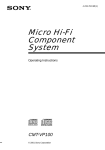
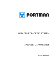
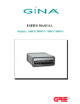
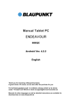
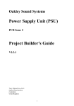
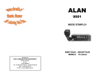
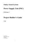
User Manual
GPS&GPRS CONTAINER TRACKING
SYSTEM
CTS100 SERIES
11/18/2008
Version 2.1
I. BRIEF INTRODUCTION
Container Tracking System utilizes the GPS and GPRS functions in one unit. You can
monitor the container or the vehicle location and set the system remotely. In addition,
the unit will send event report if any trigger occurs.
The standard report sent by the unit includes the information: (1) unit’s ID, (2) status,
(3) time, (4) GPS’s latitude and longitude, (5) speed, (6) direction, (7) battery level,
(8)device’s status, (9) event number, and (10) report configuration parameters.
The reporting mode can be categorized as ‘normal’ mode, and ‘power saving’ mode. In
normal mode, the GPS will always be activated while moving, and it can be shut off the
GPS when stop (for power saving purpose). To enable the maximum power saving,
user can choose “power saving mode”. In this mode, the GPS will be activated only
when there is a report to send while moving. The report parameters can be set from the
PC setup program. CTS100 can be set to go in sleep mode (while not moving); the
system will cut the power of GPS module in order to save power. With build-in 3-D
acceleration sensor, CTS100 can select related reporting modes with respect to it is
moving or not.
The device has built-in 4 circular, 5 rectangular and 20 point Geo-fence; it will send the
report to the server if the Geo-fence event is triggered.
The UNIT must be initialized by PC setup program in order to make communication
with the remote server /call center. There are four main sections that allow users to
program the device, (1) User detail (Device ID, server IP, and port, GPRS APN….) (2)
Geo-fence (4 circular, 5 rectangular and 20 point Geo-fence) (3) Report (Time,
Distance, speed, Low battery …) (4)Trigger report(Tamper, Door)
When there is no GPRS service or the server close. The unit will send short message to
the preset number. The max number of SMS message (monthly usage) and the
monthly renew date can be set from the pc setup program or the remote setup
program. Only 1 SMS number can be set. The reports sent via the SMS will be out again
via GPRS after a valid GPRS connection is made.
CTS100 can be configured by the PC setup program or the Over-the-Air (OTA)
commands / or remote program. The unit can communicate with the server via UDP or
TCP protocol. The protocol can be selected from the PC-setup program or remote
server commands.
Flash memory for recording reports up to 900 reports. It can be read out from the PC
setup program via serial port.
Using built-in real time clock to identify the report time, when GPS signal is lost. Hence,
if the report is received with “LAST KNOWN” message, the time in the report will be the
real time clock, but the GPS position will be the last known valid GPS position.
Three LED indicate the status of the system:
Version 2.1
1
NU_CTS100_001_12112010_EN
Power indicator: When the unit power on, the led will flash 1time/3sec by green. If the
power has low status, the LED will change to red, and the red LED will keep on when
charging mode. Even battery charge finished, the power LED will change to green. If
tamper switch is triggered, the power indicator will flash twice continuously; if door
sensor is triggered, the power indicator will flash 5 times continuously
GPS indicator: LED is GREEN when the unit has acquired a valid GPS signal, and it will
flash when the unit is searching GPS signal.
GSM/GPRS indicator: Orange LED will flash when the device is connected to the server
with valid GPRS connection. It will stay continuously on when it is in GSM mode. It will
stay off if there is no GSM reception.
Note that the GSM/GPRS and GPS LED’s indication will not be valid until the system
goes to the working mode, normally 30 seconds after power on.
II. The main unit’s housing with Strong Magnetic Gives You Easy Instant Install
Placement!
Just like we put you in control on how and when your CTS100 reports to you with your
own online controls, we also put YOU in control of how you want your CTS100 installed
on any container or vehicle.
In addition, the unit has built-in door magnetic sensor, it used to detect the container
door status.
III. BASIC FUNCTIONS
FUNCTIONS
APPLICATIONS
GPS receiver will output a complete position, velocity, and time
GPS
(PVT) solution in the NMEA Version 3.0 protocol.
GPRS use standard TCP or UDP communicate protocol. If the GPRS
GPRS, SMS
service is failed, the SMS mode will be turned on for emergency
use.
Button
Power switch
Initialize the unit and program the device, including Network APN,
server IP address, user message, report control, and Geo-fence
setting, etc …
PC-setup
Note that Network APN and server IP details must be set before the
installation.
Automatic report for tracking purpose:
Fixed time report
Standard Report
Fixed distance report
Trigger report
History data store 900 reports can be saved in unit and read from server and pc-setup
Version 2.1
2
NU_CTS100_001_12112010_EN
IV. PANEL INSTALLATION
Tamper switch
SIM card
Power switch
USB port
Built-in door
magnetic
sensor
GSM/GPRS indicator: Orange
GPS status inticator: Green
Power indicator: Green/Red
Version 2.1
3
NU_CTS100_001_12112010_EN
SIM card inserting guide:
SIM CARD LID
1. Using screwdriver to screw the screw, take out the SIM card lid.
SIM CARD
SIM card pedestal lid
2. To jog SIM card pedestal lid (step 1), then opened it about 50° (step 2)
inseting SIM card (step 3)
Version 2.1
4
NU_CTS100_001_12112010_EN
3. To set the lip of SIM card pedestal smoothly (step 1), roll it back to the
original place (step 2).
4. To cover the SIM card lip, and tighten the screw.
Version 2.1
5
NU_CTS100_001_12112010_EN
CTS100 magnetic stick installation guide
a) Press the magnetic core into magnetic stick case. (To choose case A or B base
on needed height)
the two holes lap over
the same direction
press
Magnetic core
magnetic
stick case B
magnetic
stick case A
b) Done
Door magnet B
Door magnet A
Version 2.1
6
NU_CTS100_001_12112010_EN
CTS100Installation
Installationguide
guide(Project
(Projectone:
one:
vehicle
doors
with
gasket)
CTS-100
vehicle
doors
with
gasket)
a) Drill adequate screw hole for
holder and magnetic pillar.
b) Fix holder and magnetic pillar in
appropriate position.
c) Please see the following picture, when
install the CTS100, please put one side of
it on the holder, then turn it to make the
whole undersite flat with the holder, when
disassembly, please take it down on the
opposite way.
d) Done
CTS100 Installation guide (Project two: vehicle doors without gasket)
Version 2.1
7
NU_CTS100_001_12112010_EN
b) Fix magnetic pillar in appropriate
position.
a) Drill adequate screw hole for
magnetic pillar.
door
d) Done
c)Please as follow picture, when install the
CTS100, please put one side of it on the
door of the car, then turn it to make the
whole undersite flat with the door, when
disassembly, please take it down on the
opposite way.
door
V. PC SETUP AND SYSTEM INITIATION
Version 2.1
8
NU_CTS100_001_12112010_EN
PC setup Procedure:
1.) Connect the standard RS232 cable to the DB9 port.
2.) Open the PC setup program.
3.) Select the correct COM port for communication.
4.) Click “OK” to start the program
5.) Power on the device.
Note that, if the connection fails, please check the cable connection is secured correctly.
Note: Turnover SIM card lid angle as following drawing.
SIM CARD
SIM CARD LID
SIM CARD
SIM CARD LID
A. LOGIN dialog window
Connect UNIT DB9 port to the PC serial port with a standard serial cable. Select the COM
port, and click “OK”.
Note that: it is necessary to power on the device soon after starting the PC setup program.
PC setup program will detect the hardware for 60 seconds. If no hardware is detected, it
will exit.
During the opening up screen shown as below, user can press “Esc” key to terminate the
program.
B. Version No. Checking
The below interface will last until correct UNIT Version No. is checked. (You should run
this program before turn on power of UNIT)
Version 2.1
9
NU_CTS100_001_12112010_EN
C. MAIN INTERFACE
1. [User detail]:
If the SIM card is password protected, user can input the “SIM PIN” window to set
password of SIM Card.
Version 2.1
10
NU_CTS100_001_12112010_EN
IMEI: Any operate with ‘request or request all’ after GPRS power on, the module series
number will display automatically, otherwise it displayed with space.
Set UNIT ID and UNIT password of for the device.
To select communication with GPRS or SMS, when select SMS communication; the GPRS
login information and server information are reverse video.
Set Access Point Name (APN), User Name, Password. The maximum length of the APN,
User name and Password is 49 characters.
TCP/UDP address and Port number of alarm center being set, UNIT will send message to
these address.
Note that either TCP or UDP should be selected.
Note: the IP address and port must input correctly, otherwise it will cause fail to make a
call.
Version 2.1
11
NU_CTS100_001_12112010_EN
Set the primary SMS Number of the server. The unit will send reports to the server if GPRS
connection is failed.
Setup the max number of the SMS can be sent out from the unit every month. By default, it
will be renewed by the first date of every month.
UNIT can save 900 reports (900-1). Click ‘Export’ button can export them with Excel or
Text format.
“Initialize” button: clear all data in UNIT.
Request All: read out the whole existing setting from CTS100.
Request: read out the setting in the current page.
Apply: transfer the setting to CTS100 in the current pages.
Apply All: transfer the whole setting to CTS100.
Load: load the saved configuration files.
Save: save the current configuration setting to a file.
Add to database: Add the current configuration to database
“Exit” button: exit PC-Setup to main program.
Version 2.1
12
NU_CTS100_001_12112010_EN
2. [Geo-fence]:
Four Circular Geofence
Circular Geofence must set origin and radius:
Origin format :N2446.5321E12120.4231;
N2446.5321 is latitude, E12120.4231 is longitude.
Radius from 0.1 km to 1000km.
Version 2.1
13
NU_CTS100_001_12112010_EN
Five rectangular geofence:
Set two points position, the point format is N2446.5321E12120.4231;
User can set the reports send or ignore:
Send: report will send out immediately if generation
Ignore: cancel reports.
With two points, generate one rectangle. Unit will detect whether in rectangle. When unit
enter or leave rectangle, will send one message out.
20 point Geo-fence areas can be set. When UNIT is out of these predefined zones, a report
will be generated.
3. [Report]:
Version 2.1
14
NU_CTS100_001_12112010_EN
Report setup can be configured in this section. To activate the function(s), please select “√”
in checkbox and fill in data in the textbox. There are 2 modes for the CTS100, first is the
Normal mode, and second is the Power saving mode. In normal mode, the GPS will be
always activated if CTS100 is in moving state. However, if in Power saving mode, CTS100
will turn off the GPS power if there is no report to send.
Note: that user can configure the wake up report if the device is in “stop” (not moving)
state.
(1)
Moving/stop definition
Acceleration sensor:
To determine whether CTS100 is moving or not, user can select the sensitivity of the
“acceleration sensor”. It is distinguished by the tilt angle of the device. If the unit tilted
more than the degree set here, CTS100 will be in moving mode. Otherwise, it will be in
stop mode. The smaller the parameter of degree for the sensor set in pc-setup is, the higher
the sensitivity is. Otherwise, the result is the opposite.
(2) Fixed time report
Version 2.1
15
NU_CTS100_001_12112010_EN
Parameters: On/Off, and time.
(3)
Fixed distance report
Parameters: on/off, and distance
(4)
Speeding report: (min. speed is 0.1 km/Hr, max. speed is 1000 km/Hr)
Parameters: On/Off, and speed (min. distance is 0.1 km, max. distance is 1000 km).
(5)
GPS wake up report:
While the device is in stop status, user can let the GPS go to sleep mode for power saving.
If select GPS sleep ON, user can setup the wake up report configuration/ or NO GPS wake
up report.
IF select GPS SLEEP OFF, CTS100 will follow the report-sending rule in “When Moving”
section.
(6) Power saving mode
While in Power saving mode, CTS100 will cut off the GPS power if there is no report to
send.
Report configuration will be listed as:
The fixed time report while moving: the unit will wake up automatically and enter moving
Version 2.1
16
NU_CTS100_001_12112010_EN
work mode to search GPS signal and send fix time report when moving sleep is time out,
unit will enter moving sleep mode 30 seconds later. Note: unit will search GPS signal at
first and then send report. The unit will send A report if unit searched valid signal at once;
the unit will send L report if unit searched invalid signal during 120 seconds of unit
wakened up, the unit will send A report when unit searched valid signal, unless unit enter
sleep mode again or unit power off, the unit will no way to send A report.
The unit will enter moving sleep mode again if unit auto wake up and can not search valid
GPS signal during the moving work time which user setting.
Wake up report or no GPS wake up report while stopped. In this mode, in order to save
power, unit will cut power of GPS, only wake up GPS at the time of send report.
Note: unit will enter stop mode if unit detect the tilt sensor isn’t triggered (or the trigger
angle so smaller than predetermine time) within 4 minutes during unit in moving sleep
mode
When unit entered stop sleep mode: GSM can work normally, GPS power off, the fix
reports can not send out. When unit in power saving mode, unit can not detect GPS signal,
the circular and rectangular geofence will send out maybe not in time, and the point
geofence report maybe can not send out.
(7)
GPRS dial-up procedure
1) GPRS always one-line
Parameters: Reconnect interval
While using this mode, when the unit can not searched GPRS signal, system will reconnect
GPRS interval a preset value. (e.g.: 1minute)
2) Base on report mode
Parameters: Max. reconnect times, reconnect interval
While using this mode, the unit will connect to the server when there is a report to send. If
Version 2.1
17
NU_CTS100_001_12112010_EN
the first connection is failed, it will retry to connect to the server up to the max. reconnect
times. Each retry will be separated by the reconnect “interval”.
3) GPRS connect once
While using this mode, the unit will connect to the server when there is a report to send (but
only try once). If it is not successful, the report will be stored and sent out in the next
successful connection. Disconnect GPRS connection when report sending is completed.
4) Reduce GPRS dialup method
Parameters: On/Off, Max. reconnect times, connect delay
If this method is used, the unit will reduce the GPRS dial-up connection when the dial-up is
failed after number of times. User can define the delay time for the unit before try to
reconnect to the server. If there is trigger report, the unit will connect to server immediately.
(8)
Keep alive
Keep alive procedure
Parameters: On/Off, and interval / retry times. In order to keep connection in GPRS
network, the unit can be set to send short keep alive report to the server in order to prevent
the disconnection from the mobile service provider.
Send reports after a successful keep alive ACK. Parameters: On/Off.
If you select this function, all the reports will only be sent out after a successful keep alive
ACK. (So if your keep alive time is shorter then select this function will be OK.) This
function is very useful while using UDP to prevent report lost.
Send a keep alive packet right before a due reports if no data stream within certain time:
Parameters: On/Off, and idle time.
Some GSM provider might cut connection, if there is no data within certain time. It might
result report lost in this “fake connection” duration. For example, you can set parameters in
this region, ex 20 mins. (it means if the unit did not send any data in this 20 mins (including
keep alive or normal reports) ), then it will send a keep alive packet to check if the GPRS
connection is valid or not. If not, it will actively reconnect to GPRS network.
(9) Low battery report
Version 2.1
18
NU_CTS100_001_12112010_EN
Low battery warning report (to alert user when the external battery level is low)
Parameters: On/Off, and warning battery level for report. For example, 30 to represent 30%
lower level report.
The system will ignore the parameter with a value ‘0’ to prevent continuous non-stop
reporting. Low battery, unit will cut power of GPS, only call function will be activated.
4. [Trigger report setup]
The unit has built-in door magnetic sensor and tamper switch, user can select if send report
when the door sensor and tamper switch has triggered.
1.door sensor :It will send out event reports when door on or off.
2.Tamper switch: the tamper switch is used to check the box of host, when the box of host
is moved over, it will send out a relevant report.
Version 2.1
19
NU_CTS100_001_12112010_EN
Parameter: on/off, kilometer
When acc off, unit will lock GPS, the kilometer is the radius of protecting vehicles, if
vehicle moved away the range, unit will unlock GPS.
SPECIFICATIONS
Physical Parameters
Enclosure dimensions (mm)
Unit Weight
Electrical
Operating current
Voltage (Recharge)
Current (Recharge)
Current (sleep)
96(L)*50(W)*42(H)
About 400g
52mA
5V-16V
770mA
2-15mA
Battery
Battery
Battery type
Lithium 3.7V
GPS*
Channels
Frequency
Sensitivity
Tracking
Acquisition (Cold start)
Position accuracy (Horizontal)
Battery capacity
3600mAh
Charge type
Built-in charge circuit
20 parallel tracking
L1-1575 MHz
-159 dBm
-142 dBm
<2.5m CEP autonomous
<2.0m CEP SBAX
Time to first fix
Hot start 1
<1s
Warm start 2
<32s
Cold 3
<35s
Version 2.1
20
NU_CTS100_001_12112010_EN
Standard GPS software
NMEA message switchable
GGA, GSA GSV, VTG, RMC, GLL
GPRS*
Frequency Range (MHz)
850/900/1800/1900
(Be used in CTS100MT/ CTS100FT/CTS100ST)
Frequency Range (MHz)
900&1800&1900 or
GPRS* (Be used in CTS100XT)
850&1800&1900
GPRS connectivity
GPRS multi-slot class 10
(Be used in CTS100MT/
GPRS mobile station class B
CTS100FT/CTS100XT/CTS100ST)
SIM card interface
1.8V/3.0V
(Be used in CTS100ST)
SIM card interface
3V
(Be used in CTS100MT/ CTS100FT/CTS100XT)
Antenna Impedance
(Be used in CTS100MT/
50ohms
CTS100FT/CTS100XT/CTS100ST)
IO Connection
POWER SWITCH
Communication
GPRS \SMS\RS232\USB
Environmental
Operating Temperature
Storage Temperature
-20°C to +55°C
-40°C to +85°C
Accessories
1.
Internal battery
2.
Magnetic sensor
3.
PC setup cable
Version 2.1
21
NU_CTS100_001_12112010_EN
FCC FOR CTS100XT
15.21
Federal Communications Commission (FCC) Statement
You are cautioned that changes or modifications not expressly approved by the part
responsible for compliance could void the user’s authority to operate the equipment.
15.105(b)
Federal Communications Commission (FCC) Statement
This equipment has been tested and found to comply with the limits for a Class B digital
device, pursuant to part 15 of the FCC rules. These limits are designed to provide
reasonable protection against harmful interference in a residential installation. This
equipment generates, uses and can radiate radio frequency energy and, if not installed and
used in accordance with the instructions, may cause harmful interference to radio
communications. However, there is no guarantee that interference will not occur in a
particular installation. If this equipment does cause harmful interference to radio or
television reception, which can be determined by turning the equipment off and on, the user
is encouraged to try to correct the interference by one or more of the following measures:
-Reorient or relocate the receiving antenna.
-Increase the separation between the equipment and receiver.
-Connect the equipment into an outlet on a circuit different from that to which the receiver
is connected.
-Consult the dealer or an experienced radio/TV technician for help.
Operation is subject to the following two conditions:
1) this device may not cause interference and
2) this device must accept any interference, including interference that may cause undesired
operation of the device.
FCC RF Radiation Exposure Statement:
1. This Transmitter must not be co-located or operating in conjunction with any other
antenna or transmitter.
2. This equipment complies with FCC RF radiation exposure limits set forth for an
uncontrolled environment. This equipment should be installed and operated with a
minimum distance of 20 centimeters between the radiator and your body.
Version 2.1
22
NU_CTS100_001_12112010_EN