1
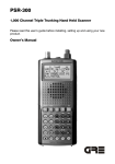
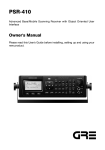
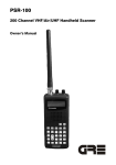
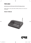
USER'S MANUAL
Models : 5000N/5000NV/7000N/7000NV
TM
General Information
GINA User’s Manual
General Information
Introduction
This document is the User’s Manual for the GINA transceiver.
NOTE: Read this manual completely before you try to use any GINA
product.
GINA Models
GINA 5000N / 5000NV
Model 5000N is a standard GINA transceiver. Model 5000NV has an
additional voice handset for audio communication. GINA 5000N receives
and transmits data in the ISM band of 902 to 928 MHz in half duplex
mode. The 5000N has a standard RS-232 serial data interface that can be
driven asynchronously at rates from 1200 through 19.2 Kbps (Optional
38.4 Kbps). GINA 5000N is autobauding and does not require any speed
adjustments between it and the DTE device. It automatically synchronizes
on any speed to 19.2 Kbps (Optional 38.4 Kbps). GINA 5000N is
designed to replace a RS-232 cable connected to a distant device. It is
plug and play transparent link to any device with a RS-2332 serial interface. There are no special setups required. GINA 5000N is a highly secure
spread spectrum radio. It does not packetize or perform any error correction and is transparent. GINA 5000N being completely transparent allows
any custom communication protocol to be used. Synchronous units at
19.2 Kbps are available as an option.
GINA 7000N / 7000NV
Model 7000N is a standard GINA transceiver. Model 7000NV has an
additional voice handset for audio communication. GINA 7000N receives
and transmits data in the ISM band of 2.404 - 2.478 GHz in half-duplex
mode. GINA 7000N utilizes a standard RS-232 serial data interface that
can be driven asynchronously at rates from 1.2 through 19.2 Kbps
(Optional 38.4 Kbps). GINA does not require any synchronization
between it and the DTE device. It automatically synchronizes on any
speed to 19.2 Kbps (Optional 38.4 Kbps). GINA 7000N will transmit at
the same speed as your asynchronous RS-232 device. GINA 7000N is
designed to replace a RS-232 cable connected to a distant device. It is a
plug and play transparent link to any device with a RS-232 serial interface. There are no special setups required.
1-1
©1999 GRE America, Inc. All rights reserved. This material is the property of GRE America, Inc. Copying or reproducing this material
is strictly prohibited. All violators shall be prosecuted to the fullest extent of the law.
7/99 (rev. 5)
General Information
GINA User’s Manual
System Requirements
For all GINA models, the only system requirement is an EIA232
(RS-232) peripheral or a personal computer (PC). When using a PC, any
communications software package such as BitCom©, Procomm©,
Crosstalk©, Windows 95/98© Hyper Terminal or any compatible communications package can be used.
What is GINA?
As shown in Figure 1-1, GINA is a high frequency data radio using
spread spectrum technology. GINA receives and transmits data in the ISM
band of 902-928 MHz or 2.404 - 2.478 GHz. GINA has standard data
interfaces that can be driven at rates from 9.6 to 38.4 Kbps (Kilobits Per
Second) depending on the model.
GINA is a plug and play transparent link. There are no special setups
required. GINA is a highly secure spread spectrum radio. GINA being
transparent allows most custom communication protocols to be used.
Figure 1-1. The GINA Transceiver
Spread Spectrum Technology
GINA uses spread spectrum technology, a technique originally developed
by the U.S. military during World War II, to prevent the jamming of communications signals. Spread spectrum technology uses a narrow bandwidth radio frequency and spreads it over a wider portion of the
bandwidth. Since the signal is spread out over the band, it renders narrow
band jammers virtually ineffective. Additionally, the spread spectrum
band can be used with low probability of interception, which is an ideal
method of communication since it is ‘radio silent’ to a conventional
receiver.
1-2
©1999 GRE America, Inc. All rights reserved. This material is the property of GRE America, Inc. Copying or reproducing this material
is strictly prohibited. All violators shall be prosecuted to the fullest extent of the law.
7/99 (rev. 5)
General Information
GINA User’s Manual
Advantages of Spread Spectrum Technology
Spread spectrum technology has many advantages. Among them are:
•
•
•
•
•
•
System flexibility. Additions can be made easily.
Interference immunity. Spread spectrum radios are immune
to noise.
Error-free communication. Automatic error detection is
built into some models.
Cost. Spread spectrum technology is inexpensive compared
to an equivalent hard-wired installation.
Data throughput. Spread spectrum technology is a transparent, real-time, point-to-point, and point-to-multipoint wireless network.
Multi-channel. Spread spectrum radios have multiple channels that can be dynamically changed with software. It allows
for repeaters, redundant base stations, and overlapping
antenna cells. A great advantage is in the dynamic control of
radio signal ‘peaks’ and ‘valleys.’
A typical spread spectrum radio signal is shown in Figure 1-2.
Figure 1-2. Spread Spectrum Radio Signal
A typical narrow band signal is shown in Figure 1-3.
Figure 1-3. Narrow Band Radio Signal
Definitions of Terms
1-3
©1999 GRE America, Inc. All rights reserved. This material is the property of GRE America, Inc. Copying or reproducing this material
is strictly prohibited. All violators shall be prosecuted to the fullest extent of the law.
7/99 (rev. 5)
General Information
GINA User’s Manual
DATA INTERFACE — The asynchronous interface port provided for
connectivity is a EIA-232 (RS232) standard.
DIRECT SEQUENCE — Direct sequence is a technique that takes a
narrow-band signal and spreads it over a broader portion of the radio
frequency band.
KEY-UP TIME — The time that a radio requires when switching from
transmit to receive and vice-versa. There is no key-up time required due
to an internal buffer. Except for Models 5000N and 7000N, data can be
received and transmitted through the RS-232 port simultaneously in a full
duplex mode using TDD (time division duplex).
NOTE: Key-up time and spreading code length are interrelated. In a
direct sequenced technique, the spread sequence system must (in real
time) attempt to match its despreading code with the incoming radio
signal in order to determine the validity of the data. The longer the
spreading code, the longer the receiver must search before it can determine that a valid data signal is being transmitted.
SYNCHRONIZATION — Applied each time that the radio switches
between transmit and receive, synchronization produces direct overhead
on each transmitted message, thereby reducing radio efficiency. In applications involving very long, constant messages (such as a large file transfer), synchronization time becomes less of a deciding factor.
MULTIPATH — Radio signals may take several paths to reach the
intended receiver. The receiver must sort out the main path from all the
‘ghost’ images. The longer the spreading factor and/or the faster the raw
data rate, the more difficult (and eventually impossible) it is to sort out the
signals, resulting in a loss of robust communication.
NUMBER OF CHANNELS — The number of channels varies per
GINA model. Models 5000N, 5000NV have 21 channels provided in the
902 - 928 MHz frequance range. Models 7000N, 7000NV have 37 channels provided in the 2.404 - 2.478 GHz frequency range. Note that the
channels are overlapping and, depending on the unit separation, only one
channel may be used.
PROCESSING GAIN MEASUREMENTS — Since processing gain is
a function of the RF bandwidth of the transmitted signal compared to the
bit rate of the data, the theoretical calculation is:
10Log(Spreading Code Rate) x (Main Lobe Factor)
RF Data Rate
NOTE: Assuming that the RF main lobe of [sin x/]2 for direct sequence is
0.88 (main lobe factor) times the bandwidth spreading code clock rate.
1-4
©1999 GRE America, Inc. All rights reserved. This material is the property of GRE America, Inc. Copying or reproducing this material
is strictly prohibited. All violators shall be prosecuted to the fullest extent of the law.
7/99 (rev. 5)
General Information
GINA User’s Manual
RANGE — The communication distance between GINA’s may vary
according to environment and application. (Robustness and range are
almost interchangeable terms; robustness and range vary according to the
antenna system used.)
RAW DATA RATE — Response time of data transmission/reception.
The raw data rate is factory set to 128 Kbps.
ROBUSTNESS — GRE America, Inc. believes that an RF link should be
‘as good as wire.’ Robustness is closely related to range. Variables for
robustness and range include:
•
•
•
•
•
Transmitter Output Power
Receiver Sensitivity
Spreading Code Length
Raw Data Rate
Antenna Configuration
NOTE: Spreading Code Length, Raw Data Rate, Robustness, and Multipath are interrelated; all terms are defined in this section.
SPREADING CODE LENGTH — A shorter spreading code length
results in better performance in measurable areas such as cost, actual data
throughput, size, range, and robustness.
A longer spreading code length reduces the possibility of unintended signal interruption and/or regulatory implications. GRE America has taken
all the above criteria and used a spreading code length of 127 chip with
four different codes selectable by channel.
SYSTEM RESPONSE TIME — Raw data rate, reflected by transmission response time. The minimum response time is 12 msec.
FCC Requirements
The FCC has allocated the frequencies between 902 – 928 MHz and
2.404 and 2.478 GHz for use with spread spectrum technology and does
not require the end user to obtain an FCC license to operate a GINA transceiver.
NOTE: Professional installers who replace GRE-provided whip antennas
with one not approved by GRE America, must obey FCC regulations concerning effective radiated power in the U.S. or the effective rules in the
destination country relating to ERP. For detail specifications, refer to FCC
Rules Part 15.247.
1-5
©1999 GRE America, Inc. All rights reserved. This material is the property of GRE America, Inc. Copying or reproducing this material
is strictly prohibited. All violators shall be prosecuted to the fullest extent of the law.
7/99 (rev. 5)
General Information
GINA User’s Manual
FCC Statement
This equipment has been tested and found to comply with the limits for a
Class B digital device, pursuant to Part 15 of the FCC Rules. These limits
are designed to provide reasonable protection against harmful interference in a residential installation. This equipment generates, uses, and can
radiate radio frequency energy and, if not installed and used in accordance
with the instructions, may cause harmful interference to radio communications. However, there is no guarantee that interference will not occur in
a particular installation. If this equipment does cause harmful interference
to radio or television reception (which can be determined by turning the
equipment off and on) the user is encouraged to try to correct the
interference by one or more of the following measures:
•
•
•
•
Re-orient or relocate the transceivers.
Increase the separation between equipment and transceivers.
Connect the equipment into a different outlet or circuit different from the one where the receiver is connected.
Consult a dealer or an experienced radio technician for help.
Shielded cables and I/O cords must be used for this equipment to comply
with relevant FCC regulations.
Changes or modifications not expressly approved in writing by GRE
America, Inc. may void the user’s authority to operate this equipment.
Customer Support
If you need answers to technical questions or require information about
product updates, please contact GRE America’s Technical Support Team
at:
Tel: (650) 591-1400
Fax: (650) 591-2001
(800) 233-5973 (outside California)
Between 8:00 A.M. and 5:00 PM, Pacific Time
Email : [email protected]
Product Returns
If, after speaking to a technical support person, it is determined that your
GINA unit requires servicing, call GRE and request a RMA number for
repair and return units. Write the RMA number on the outside of the shipping box for reference.
NOTE: Units returned without an RMA number will not be accepted.
1-6
©1999 GRE America, Inc. All rights reserved. This material is the property of GRE America, Inc. Copying or reproducing this material
is strictly prohibited. All violators shall be prosecuted to the fullest extent of the law.
7/99 (rev. 5)
General Information
GINA User’s Manual
For further information, please write us at:
GRE America, Inc.
425 Harbor Boulevard
Belmont, CA USA 94002
Attn: Customer Support
Safety Considerations
For your safety, here are some things that you should do and not do:
DO
read this manual completely before using GINA.
DO
follow all instructions carefully.
DO
use the same caution with GINA as you would use with any
electrical appliance.
DO NOT
try to use GINA for purposes for which it was not intended.
DO NOT
locate GINA in an area that does not have adequate ventilation for cooling.
DO NOT
use a ‘universal’ battery adapter with GINA. Only use the
adapter supplied with the unit.
1-7
©1999 GRE America, Inc. All rights reserved. This material is the property of GRE America, Inc. Copying or reproducing this material
is strictly prohibited. All violators shall be prosecuted to the fullest extent of the law.
7/99 (rev. 5)
5000N, 5000NV, 7000N,& 7000NV
GINA User’s Manual
GINA Models 5000N, 5000NV,
7000N, & 7000NV
Overview
Models 5000N and 7000N are standard GINA transceivers. Models
5000NV and 7000NV have an additional voice handset for audio communication. GINA 5000N receives and transmits data in the ISM band of
902 to 928 MHz in half-duplex mode. GINA 7000N receives and transmits data in the ISM band of 2.404 - 2.478 GHz in half-duplex mode.
GINA models 5000N and 7000N have a standard RS-232 serial data
interface that can be driven asynchronously at rates from 1200 through
19.2 Kbps (Optional 38.4 Kbps). GINA 5000N/7000N does not require
any synchronization between it and the DTE device. It automatically synchronizes on any speed to 19.2 Kbps (Optional 38.4 Kbps). GINA 5000N/
7000N will transmit at the same speed as your asynchronous RS-232
device. GINA 5000N/7000N is designed to replace an RS-232 cable connected to a distant device. It is a plug-and-play transparent link to any
device with a RS-232 serial interface. There are no special setups
required. GINA 5000N/7000N is a highly secure spread spectrum radio. It
does not packetize or perform error correction and is data transparent.
GINA 5000N/7000N being transparent allows custom communication
protocol to be used. Synchronous units with data rates to 19.2 Kbps are
available as an option.
Operation
This section contains operating instructions for the GINA transceiver,
including controls and indicators, timing considerations, DTE requirements, channel selection, and voice operation (Models 5000NV and
7000NV only).
2-1
©1999 GRE America, Inc. All rights reserved. This material is the property of GRE America, Inc. Copying or reproducing this material
is strictly prohibited. All violators shall be prosecuted to the fullest extent of the law.
7/99 (rev. 5)
5000N, 5000NV, 7000N, & 7000NV
GINA User’s Manual
Controls and Indicators
Front Panel
As shown in Figures 2-1 and 2-2, operating indicators and a voice handset
jack (Models 5000NV and 7000NV only) are located on the front panel,
and consist of:
1.
PWR LED (Light Emitting Diode). This LED is lit when power is
applied to the transceiver.
2.
TX LED. Indicates that a signal is being transmitted by GINA.
3.
RD LED. Indicates that a signal is being received by GINA.
4.
Voice Handset Jack. Standard RJ-11 telephone jack for the GINA
handset (Models 5000NV and 7000NV only).
NOTE: GINA only operates with the handset supplied with the unit. Do
not attempt to use a standard telephone handset.
Figure 2-1. GINA Transceiver Front Panel
Optional Voice
Handset Jack
Receive Inticator
Transmit Indicator
Power Indicator
Figure 2-1. GINA Transceiver Front Panel
2-2
©1999 GRE America, Inc. All rights reserved. This material is the property of GRE America, Inc. Copying or reproducing this material
is strictly prohibited. All violators shall be prosecuted to the fullest extent of the law.
7/99 (rev. 5)
5000N, 5000NV, 7000N,& 7000NV
GINA User’s Manual
Rear Panel
As shown in Figure 2-2, the rear panel contains a power switch and three
connectors, as follows:
1.
The GINA antenna jack (non-standard SMA type). Rear Panel
2.
ON/OFF toggle switch. Controls power to the transceiver.
3.
RS-232 connector. Standard 9-pin DIN type connector for the data
interface to a PC or DTE equipment.
4.
12 VDC. Power connector for the GINA AC to DC power converter.
5.
Receiver Signal Strength Indicator test Ports.
Receiver Signal Strength Indicator
12 Volt DC Power Supply Jack
DB9 RS-232 Interface Connector
Power On/Off Switch
Reverse SMA Type
Antenna Connector
Figure 2-2. GINA Transceiver Rear Panel
Timing Considerations
GINA 5000N/7000N does not provide nor require an external clock signal. It is capable of synchronizing on any bit rate between 1200 through
19.2 Kbps (Optional 38.4 Kbps). The transceiver transmits and receives at
the same speed as the connected asynchronous RS-232 port. No packetizing or error correction is provided; your communications software package or peripheral must provide these functions. Refer to your software/
equipment manual for details.
GINA contains a delay board that compensates for the time the sending
unit needs to acquire the receiving unit (approximately 12 milliseconds at
9600 baud).
2-3
©1999 GRE America, Inc. All rights reserved. This material is the property of GRE America, Inc. Copying or reproducing this material
is strictly prohibited. All violators shall be prosecuted to the fullest extent of the law.
7/99 (rev. 5)
5000N, 5000NV, 7000N, & 7000NV
GINA User’s Manual
GINA is a half-duplex radio and cannot transmit and receive at the same
time. If GINA is transmitting, your peripheral must wait until all data is
received before transmitting. A CTS (Clear To Send) signal is provided
when it is clear to send data back to GINA. CTS is always high in this
model. If your peripheral ignores the CTS and transmits before a valid
CTS, the data will be corrupted.
Since transmission has priority, if GINA is receiving data and the controlling peripheral begins transmitting, GINA immediately switches to transmit and the incoming data will be lost. The CTS output to the RS-232 port
is low when data is being received. After all data is received, the CTS line
is high indicating that the radio (GINA) is ready to transmit.
Refer to Figure 2-3.
Figure 2-3. GINA Transmission Timing Chart
RTS = GINA turns on and transmits a PN Carrier (This is an internal
RTS with no relationship with the RS-232 pin 7 RTS).
TXD = Transmit data
RXD = Receiving data
CTS = Clear to send
2-4
©1999 GRE America, Inc. All rights reserved. This material is the property of GRE America, Inc. Copying or reproducing this material
is strictly prohibited. All violators shall be prosecuted to the fullest extent of the law.
7/99 (rev. 5)
5000N, 5000NV, 7000N,& 7000NV
GINA User’s Manual
Channel Selection
The GINA transceiver can operate on 21 different channels (GINA model
5000NV) or 37 channels (GINA model 7000NV). The channel is factory
set at 11. When communicating with another transceiver, both units must
be set to the same channel. Depending on the time of day and local atmospheric conditions, the channel number selected can affect the range of
the unit. If you are experiencing marginal reception conditions, try changing the channel until maximum performance is reached. Channel 11 usually produces satisfactory results.
NOTE: If two systems (operating on different channels) are operating in
close proximity and are interfering with each other change the channel. If
the problem continues, a filter must be used. Contact GRE America, Inc.
Changing Channel Settings
There are either 21 (Model 5000NV) or 37 (Model 7000NV) different
channels available for use with GINA. The channel used is determined by
the settings of a 10-pin dip switch mounted on the GINA top circuit
board. The CODE column shows the switch settings for each code. GINA
is shipped with a default setting of channel 11 (1010011111). To change
this setting, change the switch positions to the desired channel.
CAUTION: Make sure that the GINA power switch is OFF and that
all cables are disconnected before changing channel settings.
There are two configurations on the GINA transceiver case. The procedures for changing switch settings are determined by the case configuration.
2-5
©1999 GRE America, Inc. All rights reserved. This material is the property of GRE America, Inc. Copying or reproducing this material
is strictly prohibited. All violators shall be prosecuted to the fullest extent of the law.
7/99 (rev. 5)
5000N, 5000NV, 7000N, & 7000NV
GINA User’s Manual
GINA Case With Switch Cutout
If you have a GINA transceiver with a switch cutout as shown in Figure
2-5:
1.
Make sure all cables are disconnected.
2.
Remove the label covering the switch cutout to get access to the
channel switch.
3.
Use a small pointed object and set each switch to the desired position.
NOTE: On the dip switch, UP (away from switch numbers) is equal
to zero. DOWN (towards switch numbers) is equal to one.
4.
Replace the switch cutout label.
Channel Dip Switch Adjustment Access Port
Figure 2-5. Transceiver Cases with Switch Cutout
“Refer to Channel Code Switch Setting table on Sections 2-7 & 2-8 “
2-6
©1999 GRE America, Inc. All rights reserved. This material is the property of GRE America, Inc. Copying or reproducing this material
is strictly prohibited. All violators shall be prosecuted to the fullest extent of the law.
7/99 (rev. 5)
5000N, 5000NV, 7000N,& 7000NV
GINA User’s Manual
CHANNEL CODE SWITCH SETTINGS
FOR GINA MODELS 5000N AND 5000NV
CHANNEL
FREQUENCY
(MHz)
DIP SWITCH
SETTING
PN
CODE
1
905.055
1010001100
1
2
906.055
1010100010
2
3
907.055
1010011010
3
4
908.055
1010110110
4
5
909.055
1010000001
2
6
910.055
1010101001
3
7
911.055
1010010101
4
8
912.055
1010111101
1
9
913.055
1010001011
3
10
914.055
1010100111
4
11
915.055
1010011111
1
12
916.055
1011110000
2
13
917.055
1011000100
3
14
918.055
1011101100
1
15
919.055
1011010010
2
16
920.055
1011111010
3
17
921.055
1011001110
1
18
922.055
1011100001
2
19
923.055
1011011001
3
20
924.055
1011110101
4
21
925.055
1011000011
1
2-7
©1999 GRE America, Inc. All rights reserved. This material is the property of GRE America, Inc. Copying or reproducing this material
is strictly prohibited. All violators shall be prosecuted to the fullest extent of the law.
7/99 (rev. 5)
5000N, 5000NV, 7000N, & 7000NV
GINA User’s Manual
CHANNEL CODE SWITCH SETTINGS
FOR GINA MODELS 7000N AND 7000NV
CHANNEL
FREQUENCY
(GHz)
DIP SWITCH
SETTING
PN CODE
1
2.404
1000100000
1
2
2.406
1000101000
2
3
2.408
1000100100
3
4
2.410
1000110100
3
5
2.412
1000100010
1
6
2.414
1000101010
2
7
2.416
1000100110
3
8
2.418
1000101110
4
9
2.420
1000111110
4
10
2.422
1000101001
2
11
2.424
1000100101
3
12
2.426
1000101101
4
13
2.428
1000100011
1
14
2.430
1000101011
2
15
2.433
1000100111
3
16
2.435
1000101111
4
17
2.437
1001100000
1
18
2.439
1001101000
2
19
2.441
1001100100
3
20
2.443
1001110100
3
21
2.445
1001100010
1
22
2.447
1001101010
2
23
2.449
1001100110
1
24
2.451
1001101110
4
2-8
©1999 GRE America, Inc. All rights reserved. This material is the property of GRE America, Inc. Copying or reproducing this material
is strictly prohibited. All violators shall be prosecuted to the fullest extent of the law.
7/99 (rev. 5)
5000N, 5000NV, 7000N,& 7000NV
GINA User’s Manual
CHANNEL CODE SWITCH SETTINGS
FOR GINA MODELS 7000N AND 7000NV
25
2.453
1001111110
4
26
2.455
1001101001
2
27
2.457
1001100101
3
28
2.59
1001101101
4
29
2.461
1001100011
1
30
2.463
1001101011
2
31
2.465
1001100111
3
32
2.467
1001101111
4
33
2.469
1010100000
1
34
2.471
1010101000
2
35
2.473
1010100100
3
36
2.475
1010110100
3
37
2.478
1010100010
1
2-9
©1999 GRE America, Inc. All rights reserved. This material is the property of GRE America, Inc. Copying or reproducing this material
is strictly prohibited. All violators shall be prosecuted to the fullest extent of the law.
7/99 (rev. 5)
5000N, 5000NV, 7000N, & 7000NV
GINA User’s Manual
Voice Operation (Models 5000NV and 7000NV Only)
NOTE: GINA only operates with the handset supplied with the unit. Do
not attempt to use a standard telephone handset.
On Models 5000NV and 7000NV, GINA is provided with a PTT (pressto-talk), release-to-listen handset that connects to the RJ-22 jack on the
front panel. This allows a remote user to communicate with the main station. Tonal quality is adequate for communication (325 to 4000 Hz) but
not telephone ‘toll grade.’ Some distortion may be noted depending on
operating environment.
Using the handset is not complicated, but since GINA operates in halfduplex mode (only one person may speak at a time, as opposed to a standard telephone, which is full duplex, allowing both stations to speak
simultaneously), we recommend military protocol: To speak, press the
PTT switch. When you are finished speaking and expect a reply, say
“over” and release the PTT button. When you are finished speaking and
do not expect a reply, say “out.”
NOTE: The voice feature on GINA Models 5000NV and 7000NV is
especially useful during installation.
Below is an illustration showing a point-to-multipoint data polling application.
Figure 3-7. Point-to-Multipoint Setup
2-10
©1999 GRE America, Inc. All rights reserved. This material is the property of GRE America, Inc. Copying or reproducing this material
is strictly prohibited. All violators shall be prosecuted to the fullest extent of the law.
7/99 (rev. 5)
5000N, 5000NV, 7000N,& 7000NV
GINA User’s Manual
5000N/5000NV SPECIFICATIONS
Adjacent Channel Rejection
-40dB = 4MHz
Baud Rate Asynchronous
1.2 to 19.2 Kbps Half Duplex - RS-232 (DB9F
Baud Rate Async. Option
38.4 Kbps Half Duplex - RS-232 (DB9F)
Channels
21 Selectable by dip switch
Control
CTS high
Data Format
Any Data Format
Dimensions
(1.52”H) x (4.17”W) x (5.0”D)
(38.6mm) x (105.9mm) x (127mm)
Dynamic Range
-100 dBm ~ -30 dBm
Frequency Range
905-928 MHz
Indicators
PWR, TxD, RxD
Modulation
Bi-Phase Shift Keying (BPSK)
PN
7 Stage (127 Chip)
PN Rate
2 Mhz
Operating Mode
Point-to-Multipoint
Operating Temperature
-20 to +60 Degrees C
Extended Temperature Option
-34 to +74 Degrees C
PN Codes
4 PN Codes
Pre-determined sequence varies within each channel
Power Consumption
10 Watt Maximum
Power Requirements
10.5 to 13.8 VDC
Radio Technique
Spread Spectrum (Direct Sequence)
Range Nominal
800+ feet
Range Indoor
500 to 1500+ feet
Range Outdoor
12+ Miles - Direct Line-of-Site FCC Compliant
Relative Humidity
0-90% Non-Condensing
Transmission Delay
20 mSec
Voice Option Interface
RJ22
2-11
©1999 GRE America, Inc. All rights reserved. This material is the property of GRE America, Inc. Copying or reproducing this material
is strictly prohibited. All violators shall be prosecuted to the fullest extent of the law.
7/99 (rev. 5)
5000N, 5000NV, 7000N, & 7000NV
GINA User’s Manual
5000N/5000NV SPECIFICATIONS
Weight
16 oz.
TRANSMITTER
Carrier Frequency Stability
15KHz
Power Consumption
700mA @ 12 VDC
Spurious Output
FCC Part 15, meets 15.245 & 15.247
Output Power
725 mW (28.6 dBm)
RECEIVER
Bit Error Rate
10 -6 @ -92 dBm
Local Oscillator Stability
15 KHz
Sensitivity Threshold
-100 dBm
Stand-by Power
325mA @ 12VDC
Signal Acquisition Time
12 mSec
Spurious Rejection
-50 dBm
2-12
©1999 GRE America, Inc. All rights reserved. This material is the property of GRE America, Inc. Copying or reproducing this material
is strictly prohibited. All violators shall be prosecuted to the fullest extent of the law.
7/99 (rev. 5)
5000N, 5000NV, 7000N,& 7000NV
GINA User’s Manual
7000N/7000NV SPECIFICATIONS
Adjacent Channel Rejection
-40dB = 4MHz
Baud Rate Asynchronous
1.2 to 19.2 Kbps Half Duplex TDD - RS-232 (DB9F)
Baud Rate Async. Option
38.4 Kbps Half Duplex - RS-232 (DB9F
Channels
37 Selectable by dip switch
Control
CTS high
Data Format
Any data format
Dimensions
(1.52”H) x (4.17”W) x (5.0”D)
(38.6mm) x (105.9mm) x (127mm)
Dynamic Range
-100 dBm ~ -30 dBm
Frequency Range
2.404 to 2.478 GHz
Indicators
PWR, TxD, RxD
Modulation
Bi-Phase Shift Keying (BPSK)
PN
7 Stage (127 Chip)
PN Rate
2 Mhz
Operating Mode
Point-to-MultiPoint
Operating Temperature
-20 to +60 Degrees C
Extended Temperature Option
-34 to +74 Degrees C
PN Codes
4 PN Codes Sequence Varies within each channel
Power Consumption
10 Watt Maximum
Power Requirements
10.5 to 13.8 VDC
Radio Technique
Spread Spectrum Direct Sequence
Range Nominal
800+ feet
Range Indoor
500 to 1500+ feet
Range Outdoor
12+ Miles - Direct Line-of-Site FCC Compliant
Relative Humidity
0-90% Non-Condensing
System Gain
119 dB
Transmission Delay
20 mSec
2-13
©1999 GRE America, Inc. All rights reserved. This material is the property of GRE America, Inc. Copying or reproducing this material
is strictly prohibited. All violators shall be prosecuted to the fullest extent of the law.
7/99 (rev. 5)
5000N, 5000NV, 7000N, & 7000NV
GINA User’s Manual
7000N/7000NV SPECIFICATIONS
Voice Option Interface
RJ22
Weight
16 oz.
TRANSMITTER
Carrier Frequency Stability
25 KHz
Power Consumption
750mA @ 12 VDC
Spurious Output
FCC Part 15, meets 15.245 & 15.247
Output Power
500 mW
RECEIVER
Bit Error Rate
10-6 @ -90 dBm
Local Oscillator Stability
25 KHz
Sensitivity Threshold
-100 dBm
Stand-by Power
400mA @ 12 VDC
Signal Acquisition Time
12 mSec
Spurious Rejection
-50 dBm
2-14
©1999 GRE America, Inc. All rights reserved. This material is the property of GRE America, Inc. Copying or reproducing this material
is strictly prohibited. All violators shall be prosecuted to the fullest extent of the law.
7/99 (rev. 5)
Appendix A: RS-232 Configuration Data
GINA User’s Manual
Appendix A: RS-232 Configuration Data
DB-9
Connector
PIN
1 - Not Used
2 - RX Data
3 - TX Data
4 - Not Used
5 - Ground
5 4 3 2 1
6 -12V DC PWR
7 - RTS
8 - CTS
9 8 7 6
9 - Not Used
DB-9
Connector
1
2
3
4
5
6
7
8
9
DB-25
Connector
—Not Used—
—Not Used—
—Not Used—
—Not Used—
8
3
2
20
7
6
4
5
22
DCD (Carrier)
RTX (Receive Data)
TXD (Transmit Data)
DTR (Data Terminal Ready)
GND (Signal Ground)
DSR (Data Set Ready)
RTS (Request to Send)
CTS (Clear to Send)
RI (Ring Indicator)
DB-9 to DB-25 SERIAL PORT
RS-232 Interface
SIGNAL
DESIGNATION
PIN
NUMBER
PIN
NUMBER
SIGNAL
DESIGNATION
1 Protective Ground
Secondary Transmitted Data 14
DCE Transmitter Signal Element Timing 15
Secondary Received Data 16
Receiver Signal Element Timing 17
18
Secondary Request to Send 19
Data Terminal Ready 20
Signal Quality Detector 21
Ring Indicator 22
Data Signal Rate Selector 23
DTE Transmitter Signal Element Timing 24
25
2 Transmitted Data
3 Received Data
4 Request to Send
5 Clear to Send
6 Data Set Ready
7 Signal Ground/Common Return
8 Received Line Signal Detector
9 + Voltage
10 – Voltage
11
12 Secondary Received Line Sinnal Indicator
13 Secondary Clear to Send
A-1
©1999 GRE America, Inc. All rights reserved. This material is the property of GRE America, Inc. Copying or reproducing this material
is strictly prohibited. All violators shall be prosecuted to the fullest extent of the law.
7/99 (rev. 5)
Appendix B: Using an External Antenna with GINA
GINA User’s Manual
Appendix B: Using an External Antenna with GINA
Introduction
This appendix contains information for users who wish to install an outside antenna to improve the transmission/reception range of GINA. GRE
America recommends that a professional electrical contractor with experience in antenna installation be used to install the antenna. Users who
wish to install their own antenna should follow the instructions below.
CAUTION: Section 810 of the National Electrical Code, ANSI/NFPA
No. 70-1994 contains the minimum legal requirements for the installation and protection of outside antennas. Consult your local building
or fire department; additional requirements may exist for your location.
NOTE: For additional information regarding outside protection, GRE
recommends that you contact Polyphaser and refer to their application
notes.
Antenna
Select an antenna suitable for the frequency range of your GINA. If a high
gain antenna is going to be used, you must obey the FCC Part 15.247 regulation. The regulation states any professional installer may change to a
different antenna and must meet the 6dBi system gain requirements.
GRE offers many optional high gain antennas that are certified with FCC.
Each contains our non-standard SMA connector. Three antennas are:
1.
13 dBi Directional Yagi Antenna with a 10 ft. cable.
2.
3 dBd Omnidirectional Antenna with a 10 ft. cable.
3.
3 dBd Patch Antenna with 3 ft. cable.
Contact a GRE sale representative for more details.
Mast/Tower
Generally, the higher the antenna is mounted the greater the improvement
in range. Fifteen to twenty feet is adequate for most locations. For longer
distances, height may need to be increased.
B-1
©1999 GRE America, Inc. All rights reserved. This material is the property of GRE America, Inc. Copying or reproducing this material
is strictly prohibited. All violators shall be prosecuted to the fullest extent of the law.
7/99 (rev. 5)
Appendix B: Using an External Antenna with GINA
GINA User’s Manual
Grounding
Make sure that the antenna system is grounded to protect against voltage
surges, built up static charges, and lightning strikes:
Use No. 10 AWG (5.3 mm) copper or No. 8 AWG (8.4 mm) aluminum
wire or larger as a ground wire.
Secure antenna lead-in and ground wires with insulated standoff insulators spaced 4-6 ft.(1.2 - 1.7 m) apart.
Mount the antenna discharge unit as close as possible to where the lead-in
enters the building.
B-2
©1999 GRE America, Inc. All rights reserved. This material is the property of GRE America, Inc. Copying or reproducing this material
is strictly prohibited. All violators shall be prosecuted to the fullest extent of the law.
7/99 (rev. 5)
Troubleshooting
GINA User’s Manual
Warranty
Introduction
This section contains user information about GRE’s limited warranty.
Limited Warranty
General
GRE America, Inc. warrants all parts of each new product to be of sound
design, good material and workmanship, and will repair or exchange any
parts proven to be defective under normal use at no charge for a period of
12 months from the date of sale to the end user.
Defects will be corrected by GRE America. There will be no charge for
labor for a period of 12 months from the date of original sale, except as
provided below. Overtime premiums and/or expedited handling and shipping costs must be paid by the owner.
Warranty Limitations
This warranty does not apply to equipment or parts that have been subject
to accident, abuse, incorrect service, alterations, service by non-authorized service personnel, misuse, or on units upon which the warranty seal
has been removed, altered, or mutilated.
A copy of the warranty certificate or purchase receipt must be supplied to
GRE America when requesting service.
Equipment must be sent to GRE America at the owner’s expense and will
be returned via surface carrier at no cost to the owner.
This warranty is strictly limited to the terms indicated herein, and no other
warranties or remedies thereunder, express or implied, shall be binding on
GRE America.
3-1
©1999 GRE America, Inc. All rights reserved. This material is the property of GRE America, Inc. Copying or reproducing this material
is strictly prohibited. All violators shall be prosecuted to the fullest extent of the law.
7/99 (rev. 5)