1
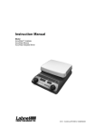
OrbitTM DIGITAL SHAKERS INSTRUCTION MANUAL Models P2, P4, M60, 300, 1000, 1900 Labnet International PO Box 841 Woodbridge, NJ 07095 Phone: 732 417-0700 Fax: 732 417-1750 email: [email protected] DIGITAL ORBIT SHAKERS TABLE OF CONTENTS 1.0. GENERAL DESCRIPTION 1.1. DEFINITION 1.2. PRINCIPLES OF OPERATION 2.0. TECHNICAL FEATURES 2.1. CONSTRUCTION 2.2. GENERAL SPECIFICATIONS 3.0. INSTALLATION 3.1. UNPACKING 3.2. SELECTING A SUITABLE LOCATION 3.3. ATTACHING POWER CORD 3.4. ENVIRONMENTAL REQUIREMENTS 4.0. PROPER INSTALATION OF SHAKER PLATFORMS (Orbit 300) 4.1. ORBIT M60, ORBIT P2, AND ORBIT P4 MODELS 4.2. ORBIT 300 MODEL PLATFORM INSTALLATION 4.3. ORBIT 1000 AND ORBIT 1900 PLATFORM INSTALLATION 5.0. OPERATING INSTRUCTIONS 5.1. INTRODUCTION 5.2. BASIC OPERATION 5.3. ADDITIONAL OPERATIONS USER’S MANUAL 2 Page 3 3 3 3 3 3 5 5 5 5 6 6 6 6 6 7 7 7 10 6.0. GENERAL PRECAUTIONS 10 7.0. TROUBLESHOOTING GUIDE 11 8.0. REGULAR MAINTANCE 11 8.1. CLEANING 11 Page 2 USER’S MANUAL DIGITAL ORBIT SHAKERS 3 1.0. GENERAL DESCRIPTION 1.1. DEFINITION Labnet’s OrbitTM Digital Shakers are intended for shaking microliter plates, tubes, bottles, flasks, dishes and other laboratory vessels. The shakers are driven by asynchronous motors, which enable silent operation and constant shaking speed independent of the load or power supply fluctuations. 1.2. PRINCIPLES OF OPERATION Each shaker device consists of two main components: - Motor with eccentric mechanism - Control electronics The motor drives the shaker’s eccentric mechanics and generates shaking effect. The electronics control the motor RPM, TIME and keyboard functions. 2.0. TECHNICAL FEATURES 2.1. CONSTRUCTION The shaker housing is made from a high-grade cold rolled steel plate and painted with a highly resistant polyurethane lacquer. 2.2. GENERAL SPECIFICATIONS: OPERATION RANGE: 4ºc TO 65ºc, 85%RH ORBIT P2, ORBIT P4, AND ORBIT M60 MODELS POWER SUPPLY MOTOR POWER FUSE RPM REGULATION SHAKER ORBIT TIMER LOAD DIMENSIONS W x L x H WEIGHT 230V 10% - 50Hz, 115V 10% - 50Hz/60Hz 15W 2 x 0.25AT, 230V 2 x 1 AT, 115V DIGITAL, load independent, from 100 to 1200 (1400 - 115V version) RPM in 10 RPM steps 3 mm 30 sec - 99min 50sec. in 10 sec. steps, under 10 min. in 1 sec. steps, timer HOLD function max. 0.3 kg 170mm x 275mm x 130mm 4,3 kg Page 3 DIGITAL ORBIT SHAKERS USER’S MANUAL 4 ORBIT 300 MODEL POWER SUPPLY MOTOR POWER FUSE RPM REGULATION SHAKER ORBIT TIMER LOAD DIMENSIONS W x L x H WEIGHT 230V 10% - 50Hz, 15V 10% - 50Hz/60Hz 15W 2 x 0.25AT, 230V 2 x 1 AT, 115V DIGITAL, load independent, from 100 to 1200 RPM in 10 RPM steps 3 mm 30 sec - 99min 50sec. in 10 sec. steps, under 10 min. in 1 sec. steps, timer HOLD function max. 2 kg 255mm x 312mm x 130mm 5,6 kg ORBIT 1000 MODEL POWER SUPPLY MOTOR POWER FUSE RPM REGULATION SHAKER ORBIT TIMER LOAD DIMENSIONS W x L x H WEIGHT 230V 10% - 50Hz, 115V 10% - 50Hz/60Hz 15W 2 x 0.25AT 230V 2 x 1 AT 115V DIGITAL, load independent, from 50 to 600 RPM in 10 RPM steps 19 mm 30 sec - 99min 50sec. in 10 sec. steps, under 10 min. in 1 sec. steps, timer HOLD function max. 4 kg 255mm x 312mm x 130mm 7,1 kg ORBIT 1900 MODEL POWER SUPPLY MOTOR POWER FUSE RPM REGULATION SHAKER ORBIT TIMER LOAD DIMENSIONS W x L x H WEIGHT 230V 10% - 50Hz, 115V 10% - 50Hz/60Hz 50W 2 x 1 AT 230V 2 x 2 AT 115V DIGITAL, load independent, from 20 to 300 RPM in 1 RPM step 19 mm 30 sec - 99min 50sec. in 10 sec. steps, under 10 min. in 1 sec. steps, timer HOLD function max. 10 kg 390mm x 465mm x 160mm 21 kg 3.0. INSTALLATION Page 4 USER’S MANUAL DIGITAL ORBIT SHAKERS 5 3.1. UNPACKING Before starting installation, carefully examine the shaker for damage or missing parts. - Open the box and lift the device together with inner packing, out of the box. - Remove the inner packing and check that the shaker has not been visibly damaged during transportation. Keep the packing material until you are sure that the shaker works properly. - Check information on the rear data label and verify the correct electrical rating: - Model - Serial Number - Electrical rating Should any kind of damage have occurred during transportation, immediately notify the carrier. The carrier is responsible for correcting damage caused in shipment. 3.2. SELECTING A SUITABLE LOCATION When selecting a location for the shaker, please consider following: - - Put the device on a smooth, horizontal and stable surface. Leave enough space around the device for normal air circulation, min. 10 cm. Leave enough space around the device, so it can be easily controlled and maintained. Don’t use the device in surroundings where there are major temperature and humidity fluctuations. Also avoid locations in direct sun light or places near devices that produce heat. Avoid locations with excessive vibrations. 3.3. ATTACHING POWER CORD Fit the main power cord, which is included in the package, into the power receptacle on the shaker. Connect the other end of the cord to a properly grounded wall outlet. To avoid interference from noise, surges and spikes, a dedicated line is preferred. If no such line is available, avoid lines to which powerful electric motors, refrigerators and similar devices are connected. Take care when you plug the cord to a grounded wall socket. Do not touch plug with wet hands. Plug the cord to a grounded wall socket only with dry hand. Page 5 USER’S MANUAL DIGITAL ORBIT SHAKERS 6 3.4. ENVIRONMENTAL REQUIREMENTS The OrbitTM digital shakers have been built for operating in both cold and heated laboratory environments and in high humidity environments as follows: At temperatures between 4C and +65C In humidity up to 85% (without condensation) 4.0. INSTALLATION OF SHAKER PLATFORMS 4.1. ORBIT M60, ORBIT P2 AND ORBIT P4 MODELS. Each of these models comes with the platform already installed. 4.2. ORBIT 300 PLATFORM INSTALLATION. mm The Orbit 300 digital shaker requires the installation of the selected platform. Please follow the instructions below for installing the platform. Slide Stabilizers Before you attach the platform, make sure that the slide stabilizers are properly fastened, adjusted and lubricated with the included grease. The flat mat platform has a circle cut-out in the rubber and screw holes in the center. Remove the cutout rubber circle and screw down the four screws onto the shaker. After attaching the platform, remove the non-adhesive backing paper on the rubber circle and paste it back into place. The grease is used to lubricate the slide stabilizers is sufficient for 1000 working hours (1 year). After that time you should remove the shaking platform and clean, adjust, and re-grease the slide stabilizers. If they are worn out, you should replace them with new stabilizers and set to appropriate height. Page 6 USER’S MANUAL DIGITAL ORBIT SHAKERS 7 4.3. ORBIT 1000 AND ORBIT 1900 PLATFORM INSTALLATION. The Orbit 1000 and Orbit 1900 model shakers have available a variety of platforms to meet most shaking needs. These platforms mount to the shakers via four mounting platforms which easily plug into four rubber mount points on the top of the shaker. 5.0. OPERATING INSTRUCTIONS 5.1. INTRODUCTION RUN TIME RPM Push Time/RPM POWER nx10 (RPM) t (min) POWER switch – switches shaker ON (light on) or OFF. RUN green signal light – lit when the shaker is running. TIME yellow signal light – lit when the shaker is set on time. RPM yellow signal light – lit when the shaker is set on rpm. ENCODER – by rotating the encoder right (+) or left (-) you can change the set TIME or RPM. Push the encoder to switch between TIME and RPM set values. If you rotate the ENCODER knob fast then values go up or down on display very quickly. 6. START/STOP button – press to START or STOP operation. 1. 2. 3. 4. 5. 5.2. BASIC OPERATION RUN TIME RPM Push Time/RPM POWER nx10 (RPM) t (min) Press the POWER switch on control panel. The OrbitTM shaker automatically detects supply frequency of 50 or 60Hz, and displays F50 or F60. Then the display switches to show the set time and illuminates the time light. Page 7 USER’S MANUAL DIGITAL ORBIT SHAKERS RUN TIME 8 RPM Push Time/RPM POWER nx10 (RPM) t (min) Time signal light is on. By rotating the encoder right (+) or left (-) the set time can be selected from 30 sec to 99 min 50 sec : 99.5 99 min 50 sec 9.59 9 min 59 sec 0.30 30 sec RUN TIME RPM Push Time/RPM POWER nx10 (RPM) t (min) If you want to set the timer to hold – turn the knob left or right until HLd is displayed. You can reach the HLd function by setting to under 0.30 or above 99.5 Push down on the encoder knob to switch modes between time set mode and RPM set mode. RUN TIME RPM Push Time/RPM POWER nx10 (RPM) t (min) RPM signal light is on. By rotating the encoder right (+) or left (-) the desired RPM can be selected : 34 340 Rpm 120 1200 Rpm Press START/STOP button to start operation Page 8 USER’S MANUAL DIGITAL ORBIT SHAKERS RUN TIME 9 RPM Push Time/RPM nx10 (RPM) POWER t (min) RUN and TIME signal lights on. Shaker runs and counts down time from set value. NOTE: YOU CAN NOT MODIFY THE SET TIME DURING SHAKING, HOWEVER, YOU CAN STOP THE UNIT WITH THE START/STOP BUTTON AND THEN RESET THE TIME. RUN TIME RPM Push Time/RPM POWER nx10 (RPM) t (min) If you want change the RPM during shaking, push the encoder knob to put the shaker into RPM set mode (RPM signal light will be on). Rotate the encoder right (+) or left (-) to set the desired value. In the meantime RPM signal light will flash. When you stop rotating the encoder knob the signal light for RPM will stop flashing after 2 sec. RUN TIME RPM Push Time/RPM POWER nx10 (RPM) t (min) When the run time has elapsed or when you press the START/STOP button, the display will show “End” and the RUN light will flash. When shaker completely stops the set speed and time will return to the last programmed values. Page 9 USER’S MANUAL DIGITAL ORBIT SHAKERS 10 5.3. ADDITIONAL OPERATIONS RUN TIME RPM Push Time/RPM POWER nx10 (RPM) t (min) If you want to view the set value for RPM during shaking rotate the encoder knob for ONE CLICK right (+) or left (-). The RPM signal light will then flash for 2 sec and the display will show the set RPM. After 2 sec the RPM and the light will stop flashing. NOTE: Shaker must be in RPM mode – RPM signal light must be on. RUN TIME RPM Push Time/RPM POWER nx10 (RPM) t (min) If you want to view the set value for TIME during shaking rotate the encoder ONE CLICK right (+) or left (-). The TIME signal light for 2 sec and the display will show the set TIME. After 2 sec the display will return to the count TIME and the signal light will stop flashing. NOTE: Shaker must be in TIME mode – TIME signal light must be on. 6.0. GENERAL PRECAUTIONS - Always plug the unit into a properly grounded and fused outlet. Do not use the device near water sources. Take care, that water will not fall on the device, especially during cleaning procedures. Do not use device in a caustic or explosive atmosphere. There are no user serviceable parts in the unit. Opening the unit may void the warranty. In case of a malfunction or liquid being spilled into the unit, unplug the device from its power outlet and contact Labnet’s service department. NOTE: Page 10 DIGITAL ORBIT SHAKERS USER’S MANUAL 11 In the case that the device does not function properly even if you have exactly followed the instructions described in the User’s manual, contact Labnet’s customer service department. If the equipment is used in a manner not specified by this manual, the equipment may become unsafe to operate, could harm the user or the device, and may void the warranty. Do not shake inflammable or explosive samples or use the unit in an inflammable or explosive environment. 7.0. TROUBLESHOOTING GUIDE Problem POWER key does not light Shaker stalls – Message Er1 Display does not light Message Er2 on display Message Er3 on display Message Er4 on display Explanation / Solution Check the power source Check fuses Power unit down, then restart Contact Labnet’s Service Department 8.0. REGULAR MAINTENANCE With the exception of the occasional maintenance described in 4.0 of this manual, no scheduled maintenance is normally required. However, an experienced technician should regularly check the device operation at least once a year to make sure it is operating correctly. Regular cleaning of the housing is recommended. 8.1. CLEANING The housing of the Shaker Unit can be cleaned with special cleaners for polyurethane (plastic) surfaces. A damp (not wet) cloth is recommended. NOTE: Do not use any aggressive or abrasive cleaners (acetone, nitro, polish, etc.) because its surface can be permanently damaged. Before cleaning the device, unplug main cord from wall socket. Page 11 DIGITAL ORBIT SHAKERS USER’S MANUAL Page 12 12