1
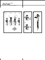
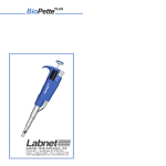
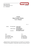
MULTICHANNEL
MULTICHANNEL
A
A1
A2
B
J
C
F
D
E
H
A
B
C
D
E
F
MULTICHANNEL
4
5
4A
4B
4C
4D
6
5A
G
J
5B
J
MULTICHANNEL
CONTENTS
1 - INTRODUCTION
2 - VOLUME SETTING
3 - METHOD OF PIPETTING
4 - RECOMMENDATIONS
5 - RECALIBRATION
6 - CLEANING AND STERILIZATION
7 - PIPETTE KIT AND ACCESSORIES
8 - SPARE PARTS
The specifications for accuracy and precision given in
the following table are obtained using Labnet tips. These
figures are only guaranteed when Labnet tips are used.
BIOPETTE PLUS 8 channel
SPECIFICATIONS
Model
Volume
[μl]
Min
BPPE-10
Max
Min
BPPE-50
Max
Min
1 - INTRODUCTION
The BIOPETTE PLUS series of adjustable multichannel
pipettes has been designed for the filling of laboratory
microplates. The pipettes enable precise and simultaneous
delivery of 8 or 12 preset-volume doses of liquid.
BIOPETTE PLUS pipettes are produced in four ranges of
volumes: 1-10 μl, 5-50 μl, 20-200 μl, 50-300 μl.
The BIOPETTE PLUS pipettes are equipped with a digital counter which shows the pipetting volume.
The set volume is visible in the window on the handle.
The setting of the volume is done by turning of the pipetting pushbutton knob (Fig. 1A2) or by turning the adjustment knob (Fig. 1B) in the correct direction. The pipette
design allows the user to lock the volume setting by
pushing the locking ring upwards (Fig.1J). The position
of the ring is indicated by the symbols located on the
handle. The volume range of the aspired liquid is shown
on the pipetting pushbutton (Fig. 1A1).
BIOPETTE PLUS pipettes should be used with polypropylene disposable tips, to ensure safety and accuracy,
(Fig. 1H). The cones without O-rings ensure the compatibility of the pipettes with a broad assortment of tips. In
order to protect the user against inadvertent contact with
used tips, the pipettes are equipped with tip ejectors,
(Fig. 1F). The special ejector shape reduces the force
required for their ejection. The pipette construction
allows to rotate the multichannel module and to eject the
tips through 360°, therefore, the most convenient position may be selected to fill the microplates. It is recommended to turn the module clockwise, (Fig.2).
1
BPPE-200
Max
Min
BPPE-300
Max
1
5
10
5
25
50
20
100
200
50
150
300
Accuracy
[%]
Precision
[%]
±8.0
±4.0
±2.0
±4.0
±3.0
±1.6
±3.0
±1.5
±1.0
±1.6
±1.2
±1.0
± 6.0
± 2.0
± 1.2
± 2.5
± 1.2
± 0.6
± 1.5
± 0.8
± 0.6
± 1.5
± 1.0
± 0.6
Fit to tips
μl
10
200
200
300
BIOPETTE PLUS 12 channel
SPECIFICATIONS
Model
Volume
[μl]
Min
BPPT-10
Max
Min
BPPT-50
Max
Min
BPPT-200
Max
Min
BPPT-300
Max
1
5
10
5
25
50
20
100
200
50
150
300
Accuracy
[%]
Precision
[%]
±8.0
±4.0
±2.0
±4.0
±3.0
±1.6
±3.0
±1.5
±1.0
±1.6
±1.2
±1.0
± 6.0
± 2.0
± 1.2
± 2.5
± 1.2
± 0.6
± 1.5
± 0.8
± 0.6
± 1.5
± 1.0
± 0.6
Fit to tips
μl
10
200
200
300
These specifications are obtained in forward mode,
using a gravimetric method with the temperature of the
distilled water, tips and all other conditions stabilized
between 19°C and 21°C. The values given include all
components of error due to both normal hand warming
and changing of the tips.
Performance tests: The pipette is calibrated in accordance with EN ISO 8655. Performance can be verified by
checking the pipette using the procedures outlined in the
EN ISO 8655 standard.
2
MULTICHANNEL
The pipette design enables the user to perform the recalibration process according to the rules presented in section 5.
2 - SETTING THE VOLUME
The setting of the volume of the aspirated liguid can be
done either by the pipetting pushbutton knob (Fig. 1A2)
or by the adjustment knob (Fig. 1B). The volume adjustment can be performed when the locking ring is set in
the lower position (Fig. 5A). When the desired volume is
selected, the locking ring should be set in the upper
position (Fig. 5B).
The volume shown by the counter is represented by
three digits, which should be read from top to bottom.
Typical meter readings are shown in the following table:
Model
BPPE-10
BPPT-10
BPPE-50
BPPT-50
BPPE-200
BPPT-200
BPPE-300
BPPT-300
Counter
readings
Set
volume
Basic
degree
0
3
5
3.5 μl
0.02 μl
0
6
5
6.5 μl
0.10 μl
0
8
5
85.0 μl
0.20 μl
2
5
0
250.0 μl
1.0 μl
To attain the maximum accuracy, set volume must be
approached from a higher value by diminishing counter
readings.
• If the desired volume is lower than set volume shown
by the counter, the operator should turn the pipetting
pushbutton (Fig. 1A2) or the adjustment knob (Fig. 1B)
to the direction diminishing counter readings to the
required volume. Before achieving the required volume
slowly rotate the knob and observe carefully diminishing reading to avoid accidentally passing the setting
value.
• If the desired volume is higher than set volume shown by
the counter, the operator should turn the pipetting push3
button (Fig. 1A2) or the adjustment knob (Fig. 1B) increasing the value until the lower figure wheel comes 1/3 of a
turn beyond the required setting and then slowly backward
until the setting reaches the desired volume. Make sure not
to pass the setting value.
If the knob is accidentally turned too far, the process
must be repeated. The desired volume must always be
set from the higher value in the order of decreasing value.
Following volume adjustment, set the locking ring into the
upper position, thus locking the knob and preventing
accidental volume change.
3 - METHOD OF PIPETTING
Fit the tips onto cones of the multichannel module. In
order to put tips on the multichannel cones hold the
pipette vertically and press it against the tips in the rack
box, until the cones retreat about 1.5 mm into the multichannel module. The suspension system of the cones
ensures even and tight sealing of tips. The pipette does
not need to be rolled back and forth to seal the tips
tightly. The liquid aspirated into the tips should not flow
out by gravity from properly fixed tips. While holding the
pipette in a vertical position, tips should be immersed in
the liquid to a depth of 2-4 mm, and flushed once by
drawing a dose of liquid and dispensing it out with slow
and steady movement. Next, still holding the pipette vertically, the operator should press the pipetting button
until the first resistance point is felt, and immerse the tips
in the liquid to the depth of 2-4 mm, (Fig. 3B). Releasing
the pipetting button with a slow and uniform movement
during 2-3 seconds, the liquid should be drawn into the
tips, (Fig. 3B) which should then be lifted above the liquid’s surface. The pipette should next be positioned at an
angle of 10-45 degrees in relation to inner walls of destination vessels and tips should be emptied by pressing
the pipetting button slowly until the first resistance point is
felt, (Fig. 3C). After waiting second, the pipetting button
should be pressed to the second resistance point in
order to expell remaining liquid, (Fig. 3D). Then tips
should be lifted out from the vessels while maintaining
contact between the ends of the tips and the inner walls
of the vessel until the pipetting button has been relased,
(Fig. 3E). Finally, pressing the ejector button, the operator should separate the tips from multichannel module’s
cones, (Fig. 3F).
4
MULTICHANNEL
4 - RECOMMENDATIONS
To achieve maximum safety, precision and reliability, the
following principles should be observed:
• do not draw liquids without tips fitted on the pipette
cones,
• do not lay down the pipette with tips filled,
• do not draw volumes of liquid exceeding the pipette’s
range,
• check if the tips are fitted properly,
• during operation, the pipette must be held vertically,
tips should be immersed in liquid to the depth of 2 to 4
milimeters and the pipetting button should be
depressed and released slowly and evenly,
• new tips must be rewetled prior to pipetting, by drawing and expelling the liquid to be measured. This is
especially important when working with liquids of viscosities and densities different from that of water and
in temperatures different from ambient temperature,
• when pipeting liquids which tend to wet walls of tips,
such as serums, proteins or organic solvents, measuring
must be performed much slower then with other liquids,
• tips must be replaced with new ones, when changing
from one liquid to another, or if drops of liquid remain
inside the tips,
• after work, the pipette should be stored vertically in a
holder with tips removed.
5 - RECALIBRATION
BIOPETTE PLUS pipettes are calibrated by gravimetric
method, using Labnet tips and distilled water, at the temperature 20±1°C, according to EN ISO 8655 standard.
If during pipette operation you find that the accuracy
error (the difference between the real aspirated volume
and the preset volume) exceeds the permissible value
given in the table in section 1, the pipette recalibration
procedure should be carried out.
Before starting the recalibration it is necessary to check
whether the following requirements have been fulfilled
during error determination:
• the ambient temperature, and the temperature of the
pipette, tips and water was identical
• the density of the liquid used is close to that of distilled
water
5
• a balance with appropriate sensitivity has been used
Volume checked [μl]
Balance sensitivity [mg]
0.1 - 10
≤ 0.001
10 - 100
≤ 0.01
> 100
≤ 0.1
• mg/μl conversion factor has been taken into account
• the requirements given in sections 3 and 4 have been
fulfilled
If the above conditions are satisfied and the accuracy
error for selected volume given in section 1 exceeds the
permissible value, the pipette recalibration procedure
should be carried out.
The recalibration can be performed within one full turn
of the key to the right or to the left only.
Recalibration conditions:
• Ambient temperature and the temperature of the pipette, tips and liquid should be within the range 20-25°C
and stabilized during weighing within ±0.5°C
• Measurements should be conducted using distilled
water
• Balance sensitivity should be suitable for the volume to
be controlled
Recalibration procedure:
• Set the dose volume depending on the pipette volume
according to the following table:
Range
of the
pipette
volumes
[μl]
Preset
volume
[μl]
Permissible
volumes
[μl]
Volume change
ΔV for full turn of
the calibration
key [μl]
(24 increments)
BPPE-10
BPPT-10
1 - 10
1
0.92 - 1.08
0.33
BPPE-50
BPPT-50
5 - 50
5
4.8 - 5.2
1.67
BPPE-200
BPPT-200
20 - 200
20
19.6 - 20.4
6.30
BPPE-300
BPPT-300
50 - 300
50
49.2 - 50.8
10.00
Model
• Perform three aspiration series (each series should
include the aspirations from all channels), weigh each
time and calculate the average value of the aspirations.
6
MULTICHANNEL
• Calculate average aspirated volume in μl multiplying
the average aspiration amount [mg] by the distilled
water density coefficient [μl/mg], which depends on
temperature and pressure according to the following
table:
Temperature [°C]
Pressure [kPa]
95.0
101.3
105.0
20
1.0028
1.0029
1.0029
21
1.0030
1.0031
1.0031
22
1.0032
1.0033
1.0033
23
1.0034
1.0035
1.0036
24
1.0037
1.0038
1.0038
25
1.0039
1.0040
1.0040
If the average aspirated volume exceeds the permissible
value, the following should be done:
• Remove the pipetting pushbutton, (Fig. 4A),
Warning: The pipetting pushbutton consists of 2 parts:
the knob (Fig. 1A2) and the pushbutton (Fig. 1A1). After
removal of the pushbutton, both parts are separated.
• Holding the volume adjustment knob to protect it
against rotation, insert the calibration key into the cuts
of the calibration screw, (Fig. 4B),
• Turn the key clockwise to reduce the aspirated volume,
or counter-clockwise to increase the volume. One full
turn of the calibration key changes the pipette aspiration volume by the amount given in the table, (Fig. 4C),
• Take out the key and fix the pipetting pushbutton
(Fig. 4D). The pipetting pushbutton should be fixed by
placing the knob on the arbor first (Fig. 1A2) and then
the pushbutton (Fig. 1A1).
Determine the average aspirated volume. The average
volume should be within the permissible range given in
the table. If the volume exceeds the values stated, the
recalibration procedure should be repeated.
6 - CLEANING AND STERILIZATION
Cleaning
External surfaces of the pipetting pushbutton, the ejector
button, the handgrip, shaft and the adjustment knob may
be cleaned using a cloth dampened in isopropyl alcohol.
7
Sterilization:
The pipette can be sterilized in the autoclave at 121°C for
20 minutes. After sterilization, the pipette should be dried
and cooled to room temperature.
It is recommended:
- to sterilize the pipette in autoclave with an initial vacuum
and drying cycle,
- prior to sterilization unscrew the nut connecting the
handle and module slightly. After autoclaving these
parts should be screwed tight again.
- to set the locking ring in lower (unlocked) position prior
to sterilization
The precision of the results should not alter if the pipetting
process and autoclaving are carried out as described
in this manual. Because a slight change in the accuracy
of the dosage may occur, it is recommended to:
- check the calibration of the pipette after the initial first,
third and fifth autoclaving cycles and then after every 10
autoclaving cycles.
7 - PIPETTE KIT AND ACCESSORIES
Pipette kit:
The pipettes are delivered in the kits including:
• Pipette
• Instruction manual
• Calibration key
• Shelf clip
• Identification labels
The shelf clip assembly diagram is shown in Fig. 6.
Accessories:
Model
Tip Choices
BPPE-10,
BPPT-10
P1000-10-R, 10 μl tips, racked
BPPE-50
BPPE-200
BPPT-50
BPPT-200
P1000-200-R, 200 μl tips, racked
BPPE-300
BPPT-300
P1000-300-R, 300 μl tips, racked
Pipettor
Stand Choices
BPPE, BPPT
P3989 Universal linear stand
8
MULTICHANNEL
8 - SPARE PARTS
The spare parts for multichannel in, (Fig. 1, 4, 5):
A: Pipetting pushbutton A1: Pushbutton A2: Knob
B: Adjustment knob
C: Ejector button
D: Piston’s assembly
E: Tip cone
F: Ejector
G: Calibration key
J: Locking ring
can be ordered from your Labnet representative (type of
pipette and name of the part for this pipette should be
specified).
Warning: The replacement of the piston requires conducting of calibration procedure according to section 5.
Before returning a pipette to a Labnet representative
please ensure that the pipette is completely free of any
contamination (chemical, microbial or radioactive).
Contact Labnet at +1 732-417-0700
fax: +1 732-417-1750
email: [email protected]
All rights reserved. Product described in this manual is subject to availability and technical modification. Errors excepted.
PZ HTL S.A. reserves the right to improve, enhance or otherwise modify
its products without prior notification.
© 2010 PZ HTL S.A.
9
BPPM/04/2010