1
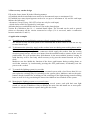
Sanviti Elettrocostruzioni s.r.l.
Via Palermo, 5/b - 43100 Parma, Italy
Phone. +39 0521.774774
Fax +39 0521.270780
e.mail: [email protected]
http://www.sanviti.it
PARMA
MULTIROX
DESIGN MANUAL
Instructions for the use of Multirox® series 4400 in the design of electrical plant.
Using Multirox® brings numerous design improvements, such as:
Fire Prevention
Automatically disconnect the electricity supply to plant during idle periods. In this way there is the
certainty that equipment and electrical systems are really switched off when not in use.
Saving energy in the use of lighting installations
Automatically switching off lighting installations when they are not needed without causing any
inconvenience to users, by connecting external control circuits to the Multirox® clocks.
Saving energy in the use of cooling and heating systems
Operational sequences for compressors, boilers, circulation pumps and fan coils are set via the
touch-screen panel. This leads to a well-organised and controlled operation of the systems leading
to significant energy savings.
In addition, there are many design improvements which can be obtained by using Multirox®.
Therefore, before starting planning, reading this document will show how simple the Multi-Clock
Panel is to use.
1. How Multirox® works
Multirox® is equipped with 10 clocks, each of which manages its own relay which has a 10 Amp
contact to which the systems to be managed are connected.
Programming the clocks is carried out via the touch-screen located on the front of the panel.
October 2008
1/4
The panel includes a terminal board where the external signals, normally push-buttons, are
connected. To each of these, one of the following three functions is attributed during programming:
PP (step-by-step), ON, OFF. Each time the push-buttons are pressed they act as a bypass on the
clocks which function according to the push-button pressed. The bypass will be removed by the
clock itself when it first acts at the pre-set time. If a permanent bypass is required on the clock, the
selector switches rather than the push-buttons need to be used. These should be programmed for
the OFF or ON functions depending on the functions required from the contact with the clock. For
example: If the functioning of a clock needs to be inhibited and its contact needs to be placed in the
OFF position, a selector switch with the input programmed to OFF needs to be used: while the
selector switch is closed, the clock contact will remain open. On the other hand, if the functioning
of a clock needs to be inhibited and its contact needs to be placed in the ON position, a selector
switch with the input programmed to ON needs to be used as the clock contact will remain closed as
long as the selector switch is closed.
Using the programming, several clocks may be bypassed by the same input and one clock may be
bypassed by several inputs. All the Multirox functions can be set from the touch-screen panel.
2. Summary diagram
Touch Screen Panel
MULTIROX – for complete system management
Comandi provenienti dall’ambiente esterno =
Commands coming from the external environment
Every external command can act on one or more clocks and are able to bypass the function status (ON –
OFF).
The various commands can come from:
- Step-by-step push-buttons (ON – OFF alternated)
- ON push-buttons – OFF push-buttons
- 0 – 1 switches
Orologi programmabili=
Programmable clocks
All clocks are programmed via the touch screen panel.
Comandi verso l’esterno=
Commands to the external environment
Each clock has its own relay to which the systems managed by the clock are connected.
Pannello Touch Screen=
Touch Screen Panel
MULTIROX
Managing the complete system
October 2008
2/4
3. How to carry out the design
Fill out the form (Annex B) in the following manner:
a) Establish which circuits/loads/users need to be disconnected (up to a maximum of 10)
b) Establish how many input bypasses need to be set (up to a maximum of 10) and for each input
indicate the following:
- the nature, if step-by-step, ON, OFF (select one only for each input)
- which clocks need to be bypassed by each input
Add what has been established in the above Form to the plant designs.
Version B of Multirox® has 10 + 1 terminal board inputs. The eleventh can be used as general
release to disconnect all the circuits connected to relays (if it is not used, make a connection
between terminals 15 and 11).
4. Application examples
4.1
To switch on an air-conditioning system or electric company logos on a building
We will use a relay for each system to be controlled and in these cases we will not use any
terminal board input.
4.2
To disconnect the electricity supply to the sockets in an area during non-working hours and be
able to re-connect them if required
We will use a relay to control the contactors which supply the sockets from the section
electricity panel and we will use two inputs from the terminal board to connect all the on/off
push-buttons. We will position these push-buttons in the most suitable location, bearing in
mind that they will be used only when necessary to by-pass the normal function set by the
clock.
Multirox® can also inhibit the function of the above push-buttons during working hours to
avoid that someone, by inadvertently pressing the OFF push-button, accidentally cuts the
power to the sockets.
4.3
To control the lighting system in a corridor
Where a corridor is equipped with a relay command system with a load lower than 10A we
can replace the existing relay for switching on the system with a Multirox® and use the pushbuttons already installed for switching on and switching off the lights during normal working
hours as well as for by-pass during the times when Multirox has switched off the system.
4.4
Managing the lighting system over several rooms
If we have one single electricity line supplying several rooms, each with their own light
switch, we can use a Multirox® relay to manage the entire line and install one or more pushbuttons in suitable locations to operate the bypass the clocks.
October 2008
3/4
4.5
Using selector switches instead of push-buttons to activate external bypass
In this case, the clock associated with this selector switch will remain bypassed for the whole
period in which the contact is closed.
For example: if there is a meeting room within a group of offices managed by Multirox® and
the lights need to be kept switched on independently of the switching-off times set at the
clocks, a selector switch needs to be installed, connected to one of the inputs and programmed
with the ON function.
As long as the selector switch keeps the contact closed, the lighting system will remain active,
independently of the programming of its clock.
Once the meeting is over, the selector switch should be turned to open the circuit and the
lights switched off as normal using its light switch, or wait until Multirox® de-activates this
circuit. If, during the day, lights need to be switched off with a dimmer switch, its SPDT C/O
contact will be used which during the day is in the ON position and on the Multirox® its input
will be programmed with the function OFF.
As seen above, it should be pointed out that, while the contact is closed, neither the clock’s
programme nor any other external push-button can change the bypass status of the clock in
question (except for input 11). This is why the use of non-pulse selector switches or other
contacts is very limited.
4.6
To control air-conditioning refrigeration groups
Refrigeration groups sometimes operate all at the same time causing spikes of energy overabsorption. To avoid this occurring, a Multirox clock should be dedicated to each refrigeration
group. All the times for the 10 clocks can then be programmed via the touch screen, keeping
one refrigeration group idle in rotation for a short period of time.
The following documents are annexed to facilitate the preparation of the plan:
A)
B)
C)
D)
Instructions for the electrical connections and programming the bypasses
Table for programming the bypasses and list of connections
Terminal board drawing
Bill of Quantities
The Multirox® Multi-Clock displays the relevant user instructions on the touch screen panel and is
also supplied with a User Manual.
October 2008
4/4
MULTIROX series 4400
Annex A
INSTRUCTIONS FOR CONNECTING MULTIROX TO
THE SYSTEM AND FOR PROGRAMMING THE BYPASSES
Compiling the Design Aid Table (Annex B)
A) Compile the table at Annex B before starting the programming and enter what the relays as well
as the inputs are connected to.
B) Alongside each input indicated at the base of the table write one of the three symbols – ON OFF – PP (Step-by-Step). This will show the function attributed to this input.
C) Several clocks may be by-passed by the same input and one clock may be by-passed by several
inputs. Therefore, place a cross on the table in the box corresponding to the input and the clock
relay to be activated.
Not every clock will necessarily have matched inputs.
D) After compiling the above, the Multirox can be programmed following the instructions in the
User Manual.
Rotating the selector switch located on the Multirox front panel towards the right to allow access to
programming. In this position, all external commands are de-activated.
Before programming the bypasses, connect terminals N13 and N11. Attention: Once the
programming is complete, remember to remove this connection.
MODELLO 4400 B: If the general release push-button is not connected, make a connection
between terminals 15 and 11.
Before making any connections, read the User Manual carefully in order to fully understand how to
use MULTIROX correctly.
Connections to the system
Each of the 10 relays is connected to the system to be activated through the relay terminals (see the
terminal board drawing attached herewith).
Input terminals: the terminals are numbered with the numbers shown in the table at Annex B.
Connect each external bypass to its own terminal on the terminal board.
Terminal number 11 is common to all inputs indicated in the table.
Supply Multirox with a single-phase 230V line.
October 2008
5/4
Annex B
MULTIROX SERIE 4400 TABLE FOR PROGRAMMING THE BYPASSES AND LIST OF
CONNECTIONS
Documento compilato in data =
document compiled on
luglio 2008 =
July 2008
INGRESSI =
INUPTS
FOR EACH INPUT, INDICATE ONE OF THE THREE SYMBOLS ON-OFF-PP (STEP-BYSTEP)
INGRESSI PROVENIENTI DA: =
MORSETTIERA=
TERMINAL BLOCK
COMUNE A TUTTI GLI INGRESSI=
COMMON TO ALL INPUTS
USCITE CONTATTI RELE COLLEGATI A:
RELAY CONTACTS OUTPUTS CONNECTED TO:
APRENDO IL CONTATTO COMANDA TUTTI I RELE' - solo per versione 4400 B =
OPENING THE CONTACT COMMANDS ALL RELAYS – only for version 4400B
October 2008
6/4
ANNEX C
MULTIROX SERIE 4400 TERMINAL BOARD
USCITA OROLOGIO =
OUTPUT CLOCK
ALIMENTAZIONE QUADRO =
PANEL POWER SUPPLY
N.10 INGRESSI PROGRAMMABILI=
10 PROGRAMMABLE INPUTS
CAVO=
CABLE
October 2008
7/4
ANNEX D
MULTIROX
- DESCRIPTION TO BE INCLUDED IN THE TECHNICAL SPECIFICATIONS MULTI-CLOCK OPERATING ALSO ON EXTERNAL COMMANDS
Multi-clock panel for saving energy and preventing fires with Multirox-type characteristics (see
www.sanviti.it)
Electrical panel equipped with touch screen, used to programme10 separate clocks as required. For
each of these, the following shall be possible:
1A) Programming up to 40 settings of daily/weekly ON and OFF times for the relays. Automatic
sequential alignment of programmed times. The display shows the next 5 programmes to
come into operation.
1B) Write on the display the name of the system to which the relay is connected with the relative
clock.
1C) Monthly and annual programming in order to insert any days in which the clocks are not
required to operate.
1D) Programming the relay settings with external commands.
2)
The display must be equipped with keys to check the adjustments made to the 10 clocks and to
be able to display the instructions for use.
3A) The electrical panel must be able to receive ON-OFF commands and Step-by-Step external
commands which bypass the clocks. The display must show to which clock the external
bypass command has been made. Several clocks shall be able to be controlled by the same
input (bypass) and one clock shall be able to be controlled by several inputs (bypass).
3B) The panel shall be prepared for reversal of the function of the 10 relays.
4)
The electrical panel, as well as those mentioned above, shall also have the following
characteristics:
• a 230V supply, key-operated security switch for programming, 10 x 10 Amp relays with
SPDT C/O contacts operated by the clocks and external commands, as indicated above.
• External PC interface.
• Possibility of one standardized release command for all the clocks.
October 2008
8/4