1
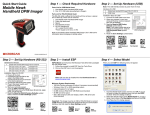
Quick Start Guide
Step 1 — Check Required Hardware
Mobile Hawk
Handheld DPM Imager
Mobile Hawk USB Hardware
1. One Mobile Hawk Handheld DPM Imager
2. One 12 ft. USB cable (pre-installed)
Mobile Hawk RS-232 Hardware
The RS-232 cable is affixed to the handle with two screws, a spacer,
and a cable clip, which can be removed.
1. One Mobile Hawk Handheld DPM Imager
2. Cable clip attachment
3. Spacer
4. Two threaded screws
5. RS-232 Interface Kit (Optional Accessory)
• 8 ft. coiled RS-232 cable
• Power supply (U.S. Euro, or UK)
Refer to the Mobile Hawk Handheld DPM Imager User’s Manual for
information about changing or adding cables.
Step 2 — Set Up Hardware (USB)
Note: The USB interface draws its power from the host.
Hardware for USB
1
Mobile Hawk Handheld DPM Imager FIS-6170-0001G
2
USB Cable
Included
Installation Steps for USB
1. Connect the USB cable (2) to
the host. You do not need to
power off your host computer.
2. Open any program in your
host computer that can receive
keyboard text.
3. Read the Reset to USB Factory
Defaults symbol below.
USB Hardware
Note: If you want symbol data
to be entered as keyboard
text, read the USB Keyboard Mode symbol below.
4. Read the Save Settings symbol below.
Reset to USB
Factory
Defaults
USB Keyboard
Mode
Test Symbol
Save
Settings
P/N 83-110022 Rev A
Step 2 — Set Up Hardware (RS-232)
Hardware for RS-232
1
3
ESP Software can be found on the Microscan Tools CD that is packaged
with the Mobile Hawk.
1. Follow the prompts to install ESP from the CD.
2. Click on the ESP icon to run the program.
Mobile Hawk Handheld DPM Imager FIS-6170-0001G
RS-232 Interface Kit (USA)
98-000074-04
RS-232 Interface Kit (Europe)
98-000074-05
RS-232 Interface Kit (UK)
98-000074-06
Step 3 — Install ESP
Installation Steps for RS-232
1. Power-off the host.
2. Attach the RS-232 cable to the
Mobile Hawk.
3. Connect the RS-232 cable to
the power supply cable.
4. Plug in the power supply and
power-on the host.
5. Open a terminal program
RS-232 Hardware
(HyperTerminal, for example)
and set 57.6K baud rate, 8
data bits, none parity, and 2 stop bits.
6. Read the Reset to RS-232 Factory Defaults symbol
below.
7. Read the Save Settings symbol below.
Test Symbol
Save
Settings
When you start ESP, the following menu will appear:
Note: ESP can also be installed from the Download Center at
www.microscan.com.
Minimum System Requirements
• 166 MHz Pentium processor (Pentium II processor recommended)
• Windows Vista, XP, or 2000 operating system
• Internet Explorer 5.0 or higher
• 64 MB minimum RAM (128+ MB RAM recommended)
• 80 MB hard drive space
• 800 x 600 minimum 256 color display (1024 x 768 32-bit color
recommended)
Important: The imager must be in USB or RS-232 Mode to connect
to ESP. Read the symbol below that corresponds with your communication
interface.
Reset to RS-232
Factory Defaults
Step 4 — Select Model
USB
Mode
RS-232
Mode
1. Click the Mobile Hawk button and then click OK. If you do
not want to make this selection every time you start ESP,
uncheck “Show this dialog at startup”.
2. Select the default imager name (Mobile Hawk-1), or type a
name of your choice in the Description text field and click OK.
3. Click Yes when this dialog appears:
Step 5 — Select Protocol
Step 6 — Connect to ESP
Select the communications protocol you are using and click Next.
USB
Step 7 — Configure the Imager
USB
Once you have clicked Connect in the USB imager ID dialog
(Step 5), the CONNECTED message will appear in a green box
in the status bar at the bottom right of the screen.
Click the Show
Connect Symbol
button
ESP’s EZ Mode is the first view that appears once you are
connected. This view features simple instructions as well as
tools for decoding symbol data and taking image captures.
You are now ready to configure the USB Mobile Hawk using ESP.
1. You will see the USB Connect Mode symbol. Print and
decode this symbol (if you have not already done so in
Step 3) to ensure that you are in the correct communications
mode. Keep the printed symbol in a convenient place for
future use. Click Next when you are finished.
2. You will then see your imager’s ID in the Select Device
field. Click Connect.
RS-232
RS-232
Once you have selected RS-232 settings and COM port and
clicked Connect, the CONNECTED message will appear in a
green box in the status bar at the bottom right of the screen.
You are now ready to configure the RS-232 Mobile Hawk using ESP.
Click the Show
Connect Symbol
button
Print and decode the RS-232 Connect Mode symbol (if
you have not already done so in Step 3) and decode it with
the imager to ensure that you are in the correct communications
mode. Keep the printed symbol in a convenient place for
future use. Click Next, and then Connect.
Step 8 — Practice Decoding
The Mobile Hawk features simple blue targeting LEDs to indicate
optimal read range.
From here, you can click on App Mode to access tree controls
and graphic user interfaces with more comprehensive configuration
options.
Illumination Quick Setup
Frequently-Used Settings
The following programming symbols allow you to control USB Keyboard
Mode, Targeting settings, and Beep and Vibration settings.
1. Hold the imager about 6”
from the mark and align
the blue targeting pattern
as shown here.
USB Keyboard
Mode
Targeting
LED On
(Default)
Vibrate On /
Beep On
(Default)
Copyright ©2009 Microscan Systems, Inc.
Save
Settings
Illumination Default
Mode
Dot Peen Enhance
Illumination Mode Large Mark
Dot Peen Enhance
Illumination Mode Medium Mark
Dot Peen Enhance
Illumination Mode Medium Mark
Targeting
LED Off
2. Move the front of the imager
steadily downward toward
the mark and parallel to the
mark surface.
3. The imager will decode the
mark at the optimal read
distance – typically from the
point of contact to .50”
(contact – 12.70 mm).
Test
Symbol
The following programming symbols allow you to set up and
control illumination settings.
Vibrate On /
Beep Off
Vibrate Off /
Beep On
Save
Settings