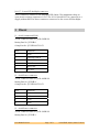
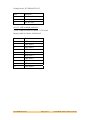
1
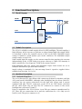
Advanced Vision Technology Limited
Form : QCF42
Date : 7 July 2008
User Manual
Issue 1.0
Unit / Module Description:
LED Back light controller
Unit / Module Number:
AV141
Document Issue Number:
1.0
Issue Date:
March 08, 2010
Original Author:
T. White
User Manual
for
AV141
Advanced Vision Technology Ltd, Thames House, Mere Park,
Dedmere Road, Marlow, SL7 1PB.
This document is the property of AVT and may not be copied nor
communicated to a third party without prior written permission.
© Advanced Vision Technology Limited 2010
User Manual AV141
Last Edited: 08/03/2010 17:29:00
Revision History
Issue
1.0
Changes Made
Initial Draft
User Manual AV141
Page 2 of 9
Date
Initials
08/03/10
TJW
Last Edited: 08/03/2010 17:29:00
Table of Contents
1
Introduction ........................................................................................................................ 4
2
Functional Description .................................................................................................... 5
2.1
Block Diagram.............................................................................................................. 5
2.2
Module Description .................................................................................................... 5
2.3
Interface Description.................................................................................................. 5
2.3.1 Mechanical Interface.............................................................................................. 5
2.3.2 Electrical Interface ................................................................................................. 6
3
Pinout.................................................................................................................................... 7
4
EMC........................................................................................................................................ 9
User Manual AV141
Page 3 of 9
Last Edited: 08/03/2010 17:29:00
1 Introduction
The AV141 is a highly versatile and efficient current controlled LED backlight
inverter. It is capable of driving and regulating backlight LED current of up to 50mA
in 16 independent channels. The LED chains can have a maximum forward voltage
of 45v.
Backlight intensity can be controlled in a number of ways. The method chosen for
control is stored in non-volatile memory, along with the backlight intensity when the
unit was last switched off. LED intensity can be controlled using a POT, an RS232
serial interface, external PWM or LED intensity can be fixed
User Manual AV141
Page 4 of 9
Last Edited: 08/03/2010 17:29:00
2 Functional Description
2.1 Block Diagram
2.2 Module Description
The AV141 is a highly versatile supply driver for LED backlights. The unit employs a
high efficiency boost converter to generate a voltage limited high side supply which
is controlled to allow the required current to flow in the LEDs. Maximum output
voltage is limited to guard against open circuit conditions. The maximum output
voltage can be set up to 60v
With a stable high side supply set, the current controller then regulates the currents
independently in the 16 LED chains at a preset value up to 50mA. LED intensity is
them controlled by “low frequency” PWM of the current control.
Both maximum high side voltage and maximum output chain current are set in
hardware and must be specified when ordering.
Supply voltage is nominally 12v, but can range from 6v (speak to supplier before
running from less that 12v) to 14v.
2.3 Interface Description
2.3.1 Mechanical Interface
The Av141 has two FFC type ribbon cable connectors designed to interface with the
AUO panel model M240HW01, although other backlights may be driven. Each FFC
connector has two power connections for the high side voltage and 8 current
regulated sink pins. The FFC connectors on the AV141 are TOP contact, such that
the FFC cable needs only one fold. The FFC connectors to connect to the screen
backlight have referenced J4 and J5.
Power is supplied to the AV141 with a 4 way PH type connector manufactured by
JST. There are two connections for 0v and two connections for +12v. Only one set
need be used. The power connector is J2
User Manual AV141
Last Edited: 08/03/2010 17:29:00
The data interface connector is a six way PH type connector also by JST. This allows
serial data to be sent to the AV141 to control the mode and brightness. There is also
a connection on this connector to drive the AV141 with an external PWM source if
required. The serial connector is J1
A potentiometer can be connected to the AV141 to allow simple control of the
brightness. The pot should be of linear type and have a value of 47K ohms. The pot
connector is J3
2.3.2 Electrical Interface
J1 – Serial communications
The AV141 can be controlled and is set up using a serial interface. This can be
connected directly to the serial port of a PC. The PC serial port must be set as the
following.
Baud rate : 9600, 8 data, 1 stop, no parity, no flow control.
The commands are send in the format of a capital letter, then a value. The letter M
indicates a Mode command and the letter B indicates a brightness value command.
There are 3 modes as follows.
M1 – internal PWM mode
M2 – External PWM mode
M3 – Full on.
Internal PWM brightness is set at follows.
B0 – off
B255 – ¼ brightness
B511 – ½ brightness
B1023 – Full brightness
Any value from 0 to 1023 can be used to set the desired brightness.
J2 – Power supply connector.
Supply range 6v to 14v, nominal and recommended 12v.
At 12v in, and running LED backlight at full brightness – the unit should take about
1.3A
J3 – Potentiometer input.
Used to connect to a 3 pin pot. The pot value should be 47K in order to achieve the
full brightness range. With a 47K pot, current flow is about 25uA. With the pot
disconnected – brightness is set controlled by internal PWM, external PWM or set to
a specific value. With the pot connected, the brightness set by the other methods is
then also moderated by the pot position. The pot will have the range from the
intensity set by the other methods down to zero.
User Manual AV141
Page 6 of 9
Last Edited: 08/03/2010 17:29:00
J4 & J5 – Screen LED backlight connector.
These connectors connect to the backlight LED chains. The maximum voltage in
open circuit on these connectors is 50v. The AV141 should NOT be connected to a
supply without BOTH of these connectors connected to the screen LED backlight.
3 Pinout
J1 – Serial Comms and PWM
AV141 Connector Part No. JST B-6B-PH-K-S
Mating Part No. JST PHR-6
Crimp Part No. JST SPH-002T-P0.5S
Pin #
Function
1
GND
2
External PWM in
3
RS232 TX
4
IIC SCL
5
RS232 RX
6
IIC SDA
J2 – Serial Power connector
AV141 Connector Part No. JST B-4B-PH-K-S
Mating Part No. JST PHR-4
Crimp Part No. JST SPH-002T-P0.5S
Pin #
Function
1
+12v
2
+12v
3
GND
4
GND
J3 – Serial Power connector
AV141 Connector Part No. JST B-3B-PH-K-S
Mating Part No. JST PHR-3
User Manual AV141
Page 7 of 9
Last Edited: 08/03/2010 17:29:00
Crimp Part No. JST SPH-002T-P0.5S
Pin #
Function
1
Pot hi end
2
Pot wiper
3
Pot low end
J4 & J5 – LED backlight connector
AV141 Connector Part No. Molex : 52745-1096
Mating Cable No. Molex : 98266-0105
Pin #
Function
1
LED chain 1
2
LED chain 2
3
LED chain 3
4
LED chain 4
5
High side +v
6
High side +v
7
LED chain 5
8
LED chain 6
9
LED chain 7
10
LED chain 8
User Manual AV141
Page 8 of 9
Last Edited: 08/03/2010 17:29:00
4 EMC
This module is designed to operate from within an enclosed host system, which is
build to provide EMC shielding. Operation within the EU EMC guidelines is not
guaranteed unless it is installed within an adequate host system.
This module is protected from damage by fast voltage transients originating from
outside the host system which may be introduced through the output cables.
Short circuiting any output to ground does not cause the host PC system to lock up
or reboot.
User Manual AV141
Last Edited: 08/03/2010 17:29:00