1
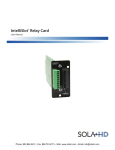
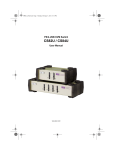
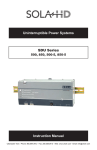
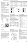
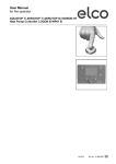
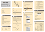
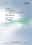
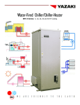
sh30 & sh45 Series power supplies
user manual
Specifications
Table 1: Technical Specifications
Input
Input voltage range
90–264 V ac; 120–300 V dc; single-phase
Frequency
47–63 Hz
Inrush current
40 A peak maximum (soft start)
Efficiency
Up to 85% at full load
Power factor
0.99 typical
Turn-on time
Ac on 1.5 s typical, inhibit/enable 150 ms typical, configurable through I2C; 50 ms internal turn-on delay (dual output only)
Hold-up time
10 ms minimum
AC OK
>5 ms early warning before outputs lose regulation, full cycle ride at 50 Hz, configurable through I2C
output
Output voltage range
±10% minimum for all outputs, user-adjustable pot, full adjustment range using I2C
Factory set point accuracy
1%
I2C output program accuracy
±5%
Margining
±4–6% nominal analog (single output module only)
Line/load regulation
0.4% or 20 mV maximum (1% maximum for 1500 W module)
Ripple
RMS: 0.1% or 10 mV maximum; Pk-Pk: 1.0% or 50 mV maximum; bandwidth limited to 20 MHz
Dynamic response
<2% or 100 mV with 25% load step
Recovery time
Within 1% in <300 µs
Overcurrent protection
Single output module and main output of the dual output module 105–120% of rated output current. Aux output of dual output module
105–140% of rated output current. Special programmable OCP delay on 1500 W module from 100 ms to 25.5 s with shutdown features.
Configurable through I2C with load calibration required (except for 1500 W module).
Short-circuit protection
Protected for continuous short-circuit; recovery is automatic upon removal of short. Shutdown mode available on the 1500 W module.
Overvoltage protection
Single output module: 2–5.5 V, 122–134%; 6–60 V, 110–120%
Dual output module: 2–6 V, 122–134%; 8–28 V, 110–120%
Triple output module: No overvoltage protection provided
Configurable through I2C
Thermal protection
All outputs are disabled when the internal temperature exceeds the safe operating range; configurable through I2C
Remote sense
Up to 0.5 V drop (not available on triple output module)
Single wire parallel
Current share to within 2% of total rated current
DC OK
±5% of nominal; configurable through I2C
Minimum load
Not required
Housekeeping bias voltage
5 V dc @ 1.0 A maximum present whenever ac input is applied
Module inhibit
Configured and controlled through I2C
Output/output isolation
>1 MΩ, 500 V
Global inhibit/enable
TTL, Logic “1” and Logic “0”; configurable through I2C
Environmental
Operating temperature
-40 °C to +70 °C ambient; derate each output 2.5% per degree from 50 °C to 70 °C; -20 °C start up
Storage temperature
-40 °C to +85 °C
Humidity
10% to 95% RH, non-condensing
Vibration
IEC68-2-6 to the levels of IEC721-3-2
MTBF demonstrated
>550,000 hr. @ full load, 220 V ac, 25 °C ambient
safety
Electromagnetic susceptibility
EN61000-4-2, EN61000-4-4, EN61000-4-5 Level 3
Conducted EMI
CISPR 22/EN55022 Level B when installed in a properly grounded and shielded metal enclosure
Radiated EMI
CISPR 22/EN55022 Level B when installed in a properly grounded and shielded metal enclosure
Certifications
, UL/CSA 60950-1 2nd Edition, CE to LVD 2006/95/EC, EN60950-1/A11:2009
General
Case specifications
SH30 Series: 5 in. x 5 in. x 11 in. [127.0 mm x 127.0 mm x 279.4 mm], 1500 W–3210 W, 09 slots available, 6.2 lb.
SH45 Series: 5 in. x 8 in. x 11 in. [127.0 mm x 203.2 mm x 279.4 mm], 1800 W–4500 W, 14 slots available, 9.0 lb.
Module weights
210 W single: 0.6 lb.; 360 W single: 1.0 lb.; 600 W single: 2.0 lb.; 750 W single: 1.6 lb.; 1500 W single: 2.0 lb.; 144 W dual: 0.6 lb.;
36 W triple: 0.5 lb.
Limited warranty
3 years
Phone: 800.894.0412 - Fax: 888.723.4773 - Web: www.clrwtr.com - Email: [email protected]
Connectors
Table 2: Ac Input
Table 3: PFC Input Connector (Control & Signals)
Pin #
1
2
3
function
N
1
~
2
barrier type
Sh30: three #6-32 b.h. screws
6 in.-lb. (0.67 n-m) max. torque
SH45: three M4 screws
7 in.-lb. (0.79 n-m) max. torque
3
Ac neutral
Dc -
Ac line (hot)
Dc +
1
6
Pin #
5
10
Mates with:
molex 90142-0010 housing
Molex 90119-2110 terminal
Connector kit available, part
number 70-841-004
+ Remote sense (single or dual o/p main)
2
Remote margin/V. program (single o/p)
3
Margin high (single o/p)
- Remote sense/margin low (single or
dual o/p main)
5
Spare
6
Module isolated inhibit (single or dual o/p)
7
Module inhibit return (single or dual o/p)
8
Current share (SWP) (single or dual o/p main)
9
+ Remote sense V2 (dual o/p, single is spare)
10
- Remote sense V2 (dual o/p, single is spare)
function
1
Input ac OK (emitter)
2
Input ac OK (collector)
3
Global dc OK (emitter)
4
Global dc OK (collector)
5
No connection
6
Global inhibit/optional enable logic “0”
7
Global inhibit/optional enable logic “1”
8
Global inhibit/optional enable return
9
+5 VSB housekeeping (1 A max.)
10
+5 VSB housekeeping return
Table 5: I2C Bus Output Connector
function
1
4
Mates with:
molex 90142-0010 housing
Molex 90119-2110 terminal
Connector kit available, part
number 70-841-004
5
10
1
6
Chassis (earth) ground
Table 4: Dc Output Module Connector (Control & Signals)
Connector J1
Pin #
Connector J1
Pin #
Connector J2
10
5
6
1
Mates with:
JST phdr-10vs housing
jst sphd-002t-p0.5 terminal
(for 24–28 AWG wire)
jst sphd-001t-p0.5 terminal
(for 24–28 AWG wire) or
landwin 2050s1000 housing
landwin 2053t011P terminal
Connector kit available, part
number 70-841-023
function
1
2
No connection
3
4
Serial clock signal (SCL)
5
Serial data signal (SDA)
6
Address bit 0 (A0)
7
Address bit 1 (A1)
8
Address bit 2 (A2)
9
Secondary return (GND)
10
5 VCC external bus (1 A max.)
notes:
• M4 x 8mm screws for all single output modules; maximum torque is 10 in.-lb. (1.13 N-m). M3 x 8mm screws for dual output
module; maximum torque is 5 in.-lb. (0.57 N-m).
• 36 W triple output module mates with Molex 09-91-0600 housing and Molex 26-60-5060 terminal.
• Single and dual output modules have a green DC OK LED.
Installation/Safety Requirements
WARNING—Risk of Electrical Shock
No user-serviceable parts. Do not open the power supply. Do not replace components.
!
• The earth ground wire must be connected only to the point marked with the earth ground symbol (on the unit). If the earth ground
wire is connected by a screw, the wire must have a ring terminal secured by a lock washer to prevent accidental loosening.
• A safety approved (e.g. UL, CSA, CE) power cord and plug, with an appropriate wire gauge for the rated input current, must be
provided by the end system manufacturer. Additional ferrites may be required on the power cord for radiated emissions testing and
are system dependent.
• The power supply must be installed in a properly grounded and shielded metal enclosure.
• An accessible disconnect device shall be installed external to the equipment.
• The power supply is CE marked following the provisions of the Low Voltage Directive 2006/95/EC only.
• Please refer to our Web site for additional information on the optional CANBUS/RS485 interface.
Phone: 800.894.0412 - Fax: 888.723.4773 - Web: www.clrwtr.com - Email: [email protected]
SH30 Series (1500/3210 W Maximum)
2.50
[63.5]
5.00 ± 0.02
[127.0 ± 0.5]
5.00 ± 0.03
[127.0 ± 0.9]
2.58
[65.5]
USB PROGRAMMING CONNECTOR
PFC INPUT CONNECTOR
I2C BUS OUTPUT CONNECTOR
1 J1 5
10 J2 6
5
1
6
DC
OK
AC
OK
0.46
[11.6]
10
0.53
[13.5]
1.32
[33.5]
0.47
[12.0]
2.26
[57.4]
REVERSE AIRFLOW DIRECTION
NORMAL AIRFLOW DIRECTION
11.00 ± 0.05
[279.40 ± 1.27]
AC INPUT
N
L
PE
4.00 ± 0.03
[101.6 ± 0.9]
0.50
[12.7]
0.75
[19.1]
6.75
[171.5]
M4 MTG HOLES (4X)
6.75
[171.5]
1.14
[29.1]
0.20
[5.0]
0.50
[12.7]
4.50
[114.3]
0.90 0.75
[22.8] [19.1]
6.75
[171.5]
notes:
• M4 mounting holes on 3 sides; #8-32 mounting holes on the bottom. Maximum penetration is 0.155 in. (4.0 mm); maximum torque is 5 in.-lb. (0.57 N-m).
• All dimensions are typical, with inches and [millimeters] shown.
Phone: 800.894.0412 - Fax: 888.723.4773 - Web: www.clrwtr.com - Email: [email protected]
SH45 Series (1800/4500 W Maximum)
8.00 ± 0.02
[203.2 ± 0.5]
3.86
[98.0]
USB PROGRAMMING CONNECTOR
PFC INPUT CONNECTOR
10 J2 6 1 J1 5
I2C BUS OUTPUT CONNECTOR
5
1 6
0.46
[11.6]
DC AC
OK OK
2.58
[65.5]
5.00 ± 0.03
[127.0 ± 0.9]
2.07
[52.6]
10
1.65
[42.0]
2.41
[61.2]
3.21
[81.5]
0.28
[7.0]
REVERSE AIRFLOW DIRECTION
NORMAL AIRFLOW DIRECTION
11.00 ± 0.05
[279.4 ± 1.3]
AC INPUT
N
L
4.00 ± 0.04
[101.6 ± 0.9]
PE
0.5
[12.7]
6.75
[171.5]
0.75
[19.1]
M4 MTG HOLES (4X)
#8-32 MTG HOLES (5X) MARKED “A”
1.15
[29.1]
0.57
[14.4]
6.75
[171.5]
0.26
[6.7] REF
0.5
[12.7]
B A
6.82
[173.3]
7.00
[177.8]
5.88
[149.4]
B A
B A
B A
B A
0.64
[16.2]
0.75
[19.1]
6.75
[171.5]
M4 MTG HOLES (5X) MARKED “B”
notes:
• M4 mounting holes on 3 sides; #8-32 mounting holes on the bottom. Maximum penetration is 0.155 in. (4.0 mm); maximum torque is 5 in.-lb. (0.57 N-m).
• All dimensions are typical, with inches and [millimeters] shown.
While every precaution has been taken to ensure accuracy and completeness in this manual, EGS Electrical Group, LLC. assumes no responsibility, and disclaims all liability for damages resulting from use of this information or for any errors or omissions. Specifications are subject to change without notice. The SolaHD and Emerson logos are registered in the U.S. Patent and Trademark Office. All other product or service names are
the property of their registered owners. ©2012 EGS Electrical Group, LLC. All rights reserved.
Phone: 800.894.0412 - Fax: 888.723.4773 - Web: www.clrwtr.com - Email: [email protected]
S3H3 & S3H5 Series power supplies
user manual
Specifications
Table 1: Technical Specifications
Input
Input voltage range
170–264 V ac, three-phase
Frequency
47–63 Hz
Inrush current
40 A peak maximum (soft start)
Efficiency
Up to 85% at full load
Power factor
0.99 typical
Turn-on time
Ac on 1.5 s typical, inhibit/enable 150 ms typical, configurable through I2C; 50 ms internal turn-on delay (dual output only)
Hold-up time
10 ms minimum
AC OK
>5 ms early warning before outputs lose regulation, full cycle ride at 50 Hz, configurable through I2C
output
Output voltage range
±10% minimum for all outputs, user-adjustable pot, full adjustment range using I2C
Factory set point accuracy
1%
I2C output program accuracy
±5%
Margining
±4–6% nominal analog (single output module only)
Line/load regulation
0.4% or 20 mV maximum (1% maximum for 1500 W module)
Ripple
RMS: 0.1% or 10 mV maximum; Pk-Pk: 1.0% or 50 mV maximum; bandwidth limited to 20 MHz
Dynamic response
<2% or 100 mV with 25% load step
Recovery time
Within 1% in <300 µs
Overcurrent protection
Single output module and main output of the dual output module 105–120% of rated output current. Aux output of dual output module
105–140% of rated output current. Special programmable OCP delay on 1500 W module from 100 ms to 25.5 s with shutdown features.
Configurable through I2C with load calibration required (except for 1500 W module).
Short-circuit protection
Protected for continuous short-circuit; recovery is automatic upon removal of short. Shutdown mode available on the 1500 W module.
Overvoltage protection
Single output module: 2–5.5 V, 122–134%; 6–60 V, 110–120%
Dual output module: 2–6 V, 122–134%; 8–28 V, 110–120%
Triple output module: No overvoltage protection provided
Configurable through I2C
Thermal protection
All outputs are disabled when the internal temperature exceeds the safe operating range; configurable through I2C
Remote sense
Up to 0.5 V drop (not available on triple output module)
Single wire parallel
Current share to within 2% of total rated current
DC OK
±5% of nominal; configurable through I2C
Minimum load
Not required
Housekeeping bias voltage
5 V dc @ 1.0 A maximum present whenever ac input is applied
Module inhibit
Configured and controlled through I2C
Output/output isolation
>1 MΩ, 500 V
Global inhibit/enable
TTL, Logic “1” and Logic “0”; configurable through I2C
Environmental
Operating temperature
-40 °C to +70 °C ambient, derate each output 2.5% per degree from 50 °C to 70 °C, -20 °C start up
Storage temperature
-40 °C to +85 °C
Humidity
10% to 95% RH, non-condensing
Vibration
IEC68-2-6 to the levels of IEC721-3-2
MTBF demonstrated
>550,000 hr. @ full load, 220 V ac, 25 °C ambient
safety
Electromagnetic susceptibility
EN61000-4-2, EN61000-4-4, EN61000-4-5 Level 3
Conducted EMI
CISPR 22/EN55022 Level B when installed in a properly grounded and shielded metal enclosure
Radiated EMI
CISPR 22/EN55022 Level B when installed in a properly grounded and shielded metal enclosure
Certifications
, UL/CSA 60950-1 2nd Edition, CE to LVD 2006/95/EC, EN60950-1/A11:2009
General
Case specifications
S3H3 Series: 5 in. x 5 in. x 11 in. [127.0 mm x 127.0 mm x 279.4 mm], 3210 W, 09 slots available, 6.0 lb.
S3H5 Series: 5 in. x 8 in. x 11 in. [127.0 mm x 203.2 mm x 279.4 mm], 4920 W, 14 slots available, 9.0 lb.
Module weights
210 W single: 0.6 lb.; 360 W single: 1.0 lb.; 600 W single: 2.0 lb.; 750 W single: 1.6 lb.; 1500 W single: 2.0 lb.; 144 W dual: 0.6 lb.;
36 W triple: 0.5 lb.
Limited warranty
3 years
Phone: 800.894.0412 - Fax: 888.723.4773 - Web: www.clrwtr.com - Email: [email protected]
Connectors
Table 2: Ac Input
S3H3
1
2
3
4
L1
L2
L3
Table 3: PFC Input Connector (Control & Signals)
S3H5
L3 L2 L1
Pin #
1
function
Line 1
2
barrier type
S3H3: four m3 screws
S3H5: three m3.5 screws
6 in.-lb. (0.67 n-m) max. torque
3
4
Line 2
Mates with:
molex 90142-0010 housing
Molex 90119-2110 terminal
Connector kit available, part
number 70-841-004
Line 3
Chassis (earth) ground
Table 4: Dc Output Module Connector (Control & Signals)
Pin #
Connector J1
1
6
5
10
+ Remote sense (single or dual o/p main)
2
Remote margin/V. program (single o/p)
3
Margin high (single o/p)
- Remote sense/margin low (single or
dual o/p main)
5
Spare
6
Module isolated inhibit (single or dual o/p)
7
Module inhibit return (single or dual o/p)
8
Current share (SWP) (single or dual o/p main)
9
+ Remote sense V2 (dual o/p, single is spare)
10
- Remote sense V2 (dual o/p, single is spare)
function
1
Input ac OK (emitter)
2
Input ac OK (collector)
3
Global dc OK (emitter)
4
Global dc OK (collector)
5
No connection
6
Global inhibit/optional enable logic “0”
7
Global inhibit/optional enable logic “1”
8
Global inhibit/optional enable return
9
+5 VSB housekeeping (1 A max.)
10
+5 VSB housekeeping return
Table 5: I2C Bus Output Connector
function
1
4
Mates with:
molex 90142-0010 housing
Molex 90119-2110 terminal
Connector kit available, part
number 70-841-004
5
10
1
6
4 3 2 1
Pin #
Connector J1
Pin #
Connector J2
10
5
6
1
Mates with:
JST phdr-10vs housing
jst sphd-002t-p0.5 terminal
(for 24–28 AWG wire)
jst sphd-001t-p0.5 terminal
(for 24–28 AWG wire) or
landwin 2050s1000 housing
landwin 2053t011P terminal
Connector kit available, part
number 70-841-023
function
1
2
No connection
3
4
Serial clock signal (SCL)
5
Serial data signal (SDA)
6
Address bit 0 (A0)
7
Address bit 1 (A1)
8
Address bit 2 (A2)
9
Secondary return (GND)
10
5 VCC external bus (1 A max.)
notes:
• M4 x 8mm screws for all single output modules; maximum torque is 10 in.-lb. (1.13 N-m). M3 x 8mm screws for dual output
module; maximum torque is 5 in.-lb. (0.57 N-m).
• 36 W triple output module mates with Molex 09-91-0600 housing and Molex 26-60-5060 terminal.
• Single and dual output modules have a green DC OK LED.
Installation/Safety Requirements
WARNING—Risk of Electrical Shock
No user-serviceable parts. Do not open the power supply. Do not replace components.
!
• The earth ground wire must be connected only to the point marked with the earth ground symbol (on the unit). If the earth ground
wire is connected by a screw, the wire must have a ring terminal secured by a lock washer to prevent accidental loosening.
• A safety approved (e.g. UL, CSA, CE) power cord and plug, with an appropriate wire gauge for the rated input current, must be
provided by the end system manufacturer. Additional ferrites may be required on the power cord for radiated emissions testing and
are system dependent.
• The power supply must be installed in a properly grounded and shielded metal enclosure.
• An accessible disconnect device shall be installed external to the equipment.
• The power supply is CE marked following the provisions of the Low Voltage Directive 2006/95/EC only.
• Please refer to our Web site for additional information on the optional CANBUS/RS485 interface.
Phone: 800.894.0412 - Fax: 888.723.4773 - Web: www.clrwtr.com - Email: [email protected]
S3H3 Series (3210 W Maximum)
5.00 ± 0.03
[127.0 ±0.9
5.00 ± 0.02
[127.0 ± 0.5]
2.58
[65.5]
2.50
[63.5]
USB PROGRAMMING CONNECTOR
I2C BUS OUTPUT CONNECTOR
PFC INPUT CONNECTOR
0.46
[11.6]
0.53
[13.5]
1.32
[33.5]
2.26
[57.4]
0.47
[12.0]
REVERSE AIRFLOW DIRECTION
NORMAL AIRFLOW DIRECTION
AC INPUT
4.00 ± 0.03
[101.6 ±0.9]
L1
L2
L3
0.50
[12.7]
0.75
[19.1]
M4 MTG HOLES (4X)
6.75
[171.5]
6.75
[171.5]
1.14
[29.1]
M4 MTG HOLES (4X) MARKED“B”
#8-32 MTG HOLES (4X) MARKED “A”
0.50
[12.7]
0.50
[12.7]
B
0.75
[19.1]
B A
B
A
A
B
A
6.75
[171.5]
notes:
• M4 mounting holes on 3 sides; #8-32 mounting holes on the bottom. Maximum penetration is 0.155 in. (4.0 mm); maximum torque is 5 in.-lb. (0.57 N-m).
• All dimensions are typical, with inches and [millimeters] shown.
Phone: 800.894.0412 - Fax: 888.723.4773 - Web: www.clrwtr.com - Email: [email protected]
S3H5 Series (4920 W Maximum)
8.00 ± 0.02
[203.2 ± 0.5]
3.86
[98.0]
USB PROGRAMMING CONNECTOR
PFC INPUT CONNECTOR
10 J2 6 1 J1 5
I2C BUS OUTPUT CONNECTOR
5
1 6
0.46
[11.6]
DC AC
OK OK
2.58
[65.5]
5.00 ± 0.03
[127.0 ± 0.9]
2.07
[52.6]
10
1.65
[42.0]
2.41
[61.2]
3.21
[81.5]
0.28
[7.0]
REVERSE AIRFLOW DIRECTION
NORMAL AIRFLOW DIRECTION
4.00 ± 0.03
[101.6 ±0.9]
AC INPUT
0.50
[12.7]
0.75
[19.1]
6.75
[171.5]
1.15
[29.1]
0.57
[14.4]
0.94
[23.9]
0.61
[15.5]
B
#8-32 MTG HOLES (5X) MARKED “A”
0.5
[12.7]
A
B
A
B
A
0.75
[19.1]
M4 MTG HOLES (4X)
6.75
[171.5]
6.75
[171.5]
B
A
B
A
0.5
[12.7]
M4 MTG HOLES (5X) MARKED “B”
notes:
• M4 mounting holes on 3 sides; #8-32 mounting holes on the bottom. Maximum penetration is 0.155 in. (4.0 mm); maximum torque is 5 in.-lb. (0.57 N-m).
• All dimensions are typical, with inches and [millimeters] shown.
While every precaution has been taken to ensure accuracy and completeness in this manual, EGS Electrical Group, LLC. assumes no responsibility, and disclaims all liability for damages resulting from use of this information or for any errors or omissions. Specifications are subject to change without notice. The SolaHD and Emerson logos are registered in the U.S. Patent and Trademark Office. All other product or service names are
the property of their registered owners. ©2012 EGS Electrical Group, LLC. All rights reserved.
Phone: 800.894.0412 - Fax: 888.723.4773 - Web: www.clrwtr.com - Email: [email protected]