1
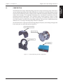
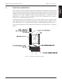
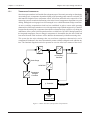
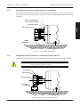
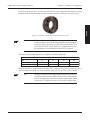
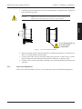
Model TMF 401–403
Torque Flange
Transducer
User’s Manual
While every precaution has been exercised in the compilation of this document to
ensure the accuracy of its contents, Magtrol, Inc. assumes no responsibility for errors
or omissions. Additionally, no liability is assumed for any damages that may result
from the use of the information contained within this publication.
COPYRIGHT
Copyright ©2003 Magtrol, Inc. All rights reserved.
Copying or reproduction of all or any part of the contents of this manual without the
express permission of Magtrol is strictly prohibited.
First Edition – August 2003
Safety Precautions
OPERATOR’S DUE CARE OBLIGATIONS
The TMF 400 Series The Torque Measuring Flange was designed and built under consideration of
a hazard analysis and upon careful selection of the harmonized standards as well as of other technical
specifications to be adhered to. Thus, the system meets the state-of-the-art requirements and
guarantees the highest safety standards. But such safety can in practice be reached only, if all the
necessary measures will have been taken. It is the machine operator’s obligation of due care, to
plan such measures and to control their execution.
Above all, the operator must assure, that:
• The system is used in accordance with the provisions as intended only (see Section 1.1)
•
The system is operated under perfect and well-functioning conditions and that specifically
the safety equipment is checked regularly for its functional integrity
•
The required personal protective equipment for the operation, maintenance, and repair
personnel is available and is in fact being used
•
The Operating Manual is always in a readable condition, and completely available at the
service location of the measuring equipment. In addition to the Operating Manual, further
operating instructions must be made available regarding occupational legislation and legal
provisions on the use of technical work aids.
•
Sufficiently qualified and authorized personnel only is executing the operation, service
and repair of the machine
•
Such personnel is trained regularly regarding all applicable questions of occupational safety
and environ-mental protection, and that such personnel is aware of the provisions of the
Operating Manual, specifically the safety instructions included
•
All safety and warning instructions attached on the machine must not be removed and shall
remain in a readable condition
SYSTEM MODIFICATIONS
For reasons of safety, no unauthorized modifications must be conducted on the measuring equipment.
Any intended modifications, mechanical or electrical must be authorized in writing by the
corresponding department of Magtrol. The given warranty expires before its regular term, if the
ordering party or any third party conducts unauthorized modifications or repairs on the delivered
systems, without the prior written approval from Magtrol.
Please use original spare parts only, because they were specifically designed for this system.
STOP
SPECIAL TYPES OF HAZARDS
If the system is operated without shaft protection device and with the top cover in the open position,
there will be the hazard of particles being thrown out after having fallen inside, or of such particles
being jammed between stator and rotor. The consequences resulting thereof may, in extreme cases,
lead to a destruction of the shaft system or to considerable personal injuries.
i
Revisions To This Manual
The contents of this manual are subject to change without prior notice. Should revisions be necessary, updates to all
Magtrol User’s Manuals can be found at Magtrol’s web site at www.magtrol.com/support/manuals.htm.
Please compare the date of this manual with the revision date on the web site, then refer to the manual’s Table of
Revisions for any changes/updates that have been made since this edition.
REVISION DATE
First Edition – August 2003
TABLE OF REVISIONS
First Edition – no revisions made to date.
ii
Table of Contents
SAFETY PRECAUTIONS ......................................................................................................................... i
OPERATOR’S DUE CARE OBLIGATIONS ........................................................................................................................ i
SYSTEM MODIFICATIONS ................................................................................................................................................ i
SPECIAL TYPES OF HAZARDS ......................................................................................................................................... i
REVISIONS TO THIS MANUAL ............................................................................................................... ii
REVISION DATE .................................................................................................................................................................ii
TABLE OF REVISIONS ......................................................................................................................................................ii
TABLE OF CONTENTS ......................................................................................................................... iii
PREFACE ................................................................................................................................................ v
PURPOSE OF THIS MANUAL ........................................................................................................................................... v
WHO SHOULD USE THIS MANUAL ................................................................................................................................ v
MANUAL ORGANIZATION ............................................................................................................................................... v
CONVENTIONS USED IN THIS MANUAL ..................................................................................................................... vi
1. INTRODUCTION ................................................................................................................................ 1
1.1 INTENDED USE ........................................................................................................................................................... 1
1.2 COMPOSITION ............................................................................................................................................................ 2
1.3 FUNCTIONAL DESCRIPTION ................................................................................................................................... 3
1.3.1
Temperature Compensation ............................................................................................................................. 4
1.3.2
Optional Measuring Range .............................................................................................................................. 5
1.4 DATA SHEET ................................................................................................................................................................ 6
2. INSTALLATION/CONFIGURATION ................................................................................................. 10
2.1 INSTALLATION SAFETY ......................................................................................................................................... 10
2.1 MECHANICAL INSTALLATION OF MEASURING FLANGE AND STATOR ..................................................... 11
2.1.1
Suspended Installation ................................................................................................................................... 11
2.1.2
Front-Mounting of Stator and Flange Close to a Bearing ............................................................................. 12
2.1.3
Base-Mounted Stator Directly at the Machine Power Take-Off .................................................................... 12
2.2 TMF WITH SIGNAL BOX .......................................................................................................................................... 14
2.3 MECHANICAL INSTALLATION STEP BY STEP ................................................................................................... 14
2.3.1
Installtion Dimensions ................................................................................................................................... 15
2.4 ELECTRIC CONNECTIONS ...................................................................................................................................... 16
3. SIGNAL BOX .................................................................................................................................... 17
3.1 INTRODUCTION ........................................................................................................................................................ 17
3.1.1
Features .......................................................................................................................................................... 17
3.2 INSTALLATION ......................................................................................................................................................... 18
3.2.1
Component Control ....................................................................................................................................... 18
3.2.2
Component Connection ................................................................................................................................. 18
3.3 CONFIGURATION ..................................................................................................................................................... 19
3.3.1
External Power Supply .................................................................................................................................. 19
3.3.2
Grounding ...................................................................................................................................................... 19
3.3.3
Accident Prevention ....................................................................................................................................... 19
3.3.4
Pin Assignment .............................................................................................................................................. 20
3.3.5
Connecting the RS422 I/O (optional) ............................................................................................................ 21
3.3.6
Connecting the TCU1 with a PC ................................................................................................................... 21
iii
Table of Contents
Magtrol TMF Torque Flange Transducer
3.4 SETTINGS ................................................................................................................................................................... 22
3.4.1
Operating Principle ........................................................................................................................................ 22
MAGTROL LIMITED WARRANTY ........................................................................................................ 23
TABLE OF FIGURES
CHAPTER 1
Figure 1–1
Figure 1–2
Figure 1–3
Figure 1–4
Torque Measuring System Configuration ............................................................................................... 2
Composition of Measuring Flange ......................................................................................................... 3
Basic Structure of Temperature Compensation ...................................................................................... 4
Basic Structure of the Second Torque Measuring Range ....................................................................... 5
Figure 2–1
Figure 2–2
Figure 2–3
Figure 2–4
Figure 2–5
Figure 2–6
Figure 2–7
Figure 2–8
Suspended Installation ......................................................................................................................... 11
Front Mounted Installation .................................................................................................................. 12
Base (or Foot) Mounted Installation .................................................................................................... 12
Torsion-resistant Shaft Clutch Element, Type 920 ............................................................................... 13
Removal of Cover ................................................................................................................................. 14
Flange Plate ......................................................................................................................................... 14
Insertion of Measuring Shaft ................................................................................................................ 15
Connecting TMF Measuring Flange with Signal Box ......................................................................... 16
Figure 3–1
Figure 3–2
Figure 3–3
TCU1-SB1 Signal Box .......................................................................................................................... 17
RS422 Output Signal Connection ........................................................................................................ 21
Operation Flowchart ............................................................................................................................ 22
CHAPTER 2
CHAPTER 3
iv
Preface
PURPOSE OF THIS MANUAL
This manual contains all the information required for the setup TMF 400 Series Torque Flange
Transducers. To achieve maximum capability and ensure proper use of the transducers, please read
this manual in its entirety before operating. Keep the manual in a safe place for quick reference
whenever a question should arise.
WHO SHOULD USE THIS MANUAL
This User’s Manual was compiled for those individuals concerned with the planning, assembly and
the taking into service of torque measurement equipment and systems with torque measuring shafts.
General knowledge of mechanical and electrical engineering is required as a prerequisite for the
installation and the operation of the system. The torque measurement system should be operated by
those individuals only, who have been trained, instructed, and authorized on the system. Such
personnel must be familiar with the User’s Manual and must be acting accordingly. The individual
authorizations of the operating personnel must be clearly defined.
MANUAL ORGANIZATION
This section gives an overview of the structure of the manual and the information contained within
it. Some information has been deliberately repeated in different sections of the document to minimize
cross-referencing and to facilitate understanding through reiteration.
The structure of the manual is as follows:
Chapter 1:
INTRODUCTION - Describes the composition and functions of the TMF 400 Series
Torque Flange Transducers and contains the technical data sheet which provides
the mechanical and electrical characteristics.
Chapter 2:
INSTALLATION/CONFIGURATION - Provides information needed for setup of
the TMF Transducers including mounting options, electrical connections and stepby-step instructions for mechanical installation.
v
Preface
Magtrol TMF Torque Flange Transducer
CONVENTIONS USED IN THIS MANUAL
The following symbols and type styles may be used in this manual to highlight certain parts of the
text:
Note:
This is intended to draw the operator’s attention to complementary
information or advice relating to the subject being treated. It
introduces information enabling the correct and optimal functioning
of the product to be obtained.
CAUTION:
THIS
IS USED TO DRAW THE OPERATOR’S ATTENTION TO INFORMATION,
DIRECTIVES, PROCEDURES, ETC. WHICH, IF IGNORED, MAY RESULT IN DAMAGE
BEING CAUSED TO THE MATERIAL BEING USED.
THE
ASSOCIATED TEXT
DESCRIBES THE NECESSARY PRECAUTIONS TO TAKE AND THE CONSEQUENCES
THAT MAY ARISE IF THE PRECAUTIONS ARE IGNORED.
WARNING!
STOP
THIS INTRODUCES DIRECTIVES, PROCEDURES,
PRECAUTIONARY MEASURES, ETC. WHICH MUST BE
EXECUTED OR FOLLOWED WITH THE UTMOST CARE
AND ATTENTION, OTHERWISE THE PERSONAL
SAFETY OF THE OPERATOR OR THIRD PARTY MAY BE
PUT AT RISK. THE READER MUST ABSOLUTELY TAKE
NOTE OF THE ACCOMPANYING TEXT, AND ACT UPON
IT, BEFORE PROCEEDING FURTHER.
vi
1.1
INTENDED USE
The TMF 400 Series Torque Measuring Flange has been intended exclusively for the measurement
of the mechanical performance parameters torque and speed. Any use in an explosive hazard
environment is not permitted.
Due to the high accuracy of measurement of the system, a multiple installation on one drive shaft
system is possible, e.g. for efficiency measurements. The telemetric transmission procedure has
been designed in such a way, that there is no mutual interference when systems are placed in a close
arrangement next to each other.
Since the system has been set up without bearings, the specified distances between rotor and stator
must be maintained under all operating conditions.
For the utilization of the full measuring accuracy it must be observed, that the acting radial forces
and torsional vibrations will not exceed the permissible load limit values.
1
GENERAL
INFORMATION
1. Introduction
Chapter 1 – Introduction
COMPOSITION
The TMF 400 Series Torque Measuring Flange represents a torque measuring system which can be
used in multiple applications and in many different ways, based on its connecting flanges on both
sides. Since this measuring system is equipped with a contactless functioning telemetric system and
without roller bearings, it is completely maintenance-free, and therefore specifically suited for
permanent-operation applications. The extremely high overload capacity, despite its high
measurement accuracy of typically 0.1% of the scale end value, will enable this system to be used
as a clutch element even under critical operating conditions. The new series, which includes four
different sizes is covering a measuring range from 50 to 6,000 Nm.
One functional unit is composed of the measuring flange itself (rotor), one housing with upper and
lower stator part, one main cable and one signal box.
Figure 1–1 Torque Measuring System Configuration
2
GENERAL
INFORMATION
1.2
Magtrol TMF Torque Flange Transducer
Chapter 1 – Introduction
Magtrol TMF Torque Flange Transducer
FUNCTIONAL DESCRIPTION
Each TM 400 Series torque transducer registers the elongation of the shaft body generated by the
acting torque by means of strain gauges and transmits these signals to the stator side in the form of
frequency-modulated infrared light. An optional second infrared data link can be utilized for the
transmission of a second, considerably smaller torque measuring range. A shifting of the zero
signal that can be possibly caused by temperature effects will be suppressed on site as much as
possible by a µ-controlled compensation circuit.
A standard-type integrated speed registration system will, at the same time, provide a high-resolution
speed signal featuring two 90°-displacement speed tracks. Upon utilization of the magneto-resistive
effect, stable square-wave, speed-proportional signals are available beginning with zero speed.
The relevant measuring units can be tapped off the signal box in an analog form or as frequency
signals.
Figure 1–2 Composition of Measuring Flange
3
GENERAL
INFORMATION
1.3
Chapter 1 – Introduction
TEMPERATURE COMPENSATION
Since the torque transducer itself and the first subsequent steps of electronic processing are functioning
on an analog basis, a temperature-dependent shifting of the operating points cannot be excluded. The
shaft material elongation due to temperature effects will become noticeable at the output side of the
measuring system as an undesired measuring value in the form of a temperature-dependent zero point
drifting, although the strain gauges have been arranged in a so-called Wheatstone bridge connection.
An active switching compensation circuit has been established in order to assure stable operating
characteristics of the torque transducer over a wide temperature range. With the support of a µ-Controller
integrated at the rotating side, temperature data which was determined in an expensive way during the
manufacture of the system is picked up and stored in a so-called Lock-Up Table. If during operation of
the integrated temperature sensor a change in temperature is determined, then the value which had
been stored from the Table in advance will be added to the momentarily available measuring value.
This system has the major advantage that even non-linear temperature characteristics can be
compensated. Furthermore, the values determined by means available at Magtrol can be edited at any
time. The functional diagram shown below presents an overview of the basic structure of the circuit.
V
+
F
Amplifier
Voltage
to Frequency
Converter
IR-Transmission
Strain Gauge
A
16-Bit DAC
D
T
D
Temperature
to Digital
Converter
µ - Controller
Serial
Interface
EEPROM
16-Bit
(temperature values)
Figure 1–3 Basic Structure of Temperature Compensation
4
GENERAL
INFORMATION
1.3.1
Magtrol TMF Torque Flange Transducer
Chapter 1 – Introduction
Magtrol TMF Torque Flange Transducer
OPTIONAL MEASURING RANGE
The entire system was designed in such a way, that the optional second measuring amplifier and a
second infrared transmission data link can be integrated together with the manufacture of the transducer.
This second amplifier is able to increase the signals originating from the joint measuring bridge circuit
in such a way, that a second high-resolution measuring range can be used for the registration of much
smaller torque values. Thus, the often necessary exchange of the torque transducer for the precise
measurement of smaller torque values can be deleted. This partial measuring circuit is equipped with
the temperature compensation described above and with the SHUNT calibration (see Figure 1–3).
Note:
It must be observed, when utilizing the full accuracy of
measurement of the smaller measuring range, that the shaft
assembly should be stopped and released from the load, after having
conducted a measuring cycle with a high torque load. Then, the
zero push button must be pressed, unless otherwise the hysteresis
values “stored” before in the spring body would, by principle,
superimpose itself on the second, more sensitive measuring channel.
V
+
F
Amplifier 2
Voltage
to Frequency
Converter
IR-Transmission
V
+
F
Amplifier 1
Voltage
to Frequency
Converter
IR-Transmission
Strain Gauge
16-Bit
DAC
T
D
A
A
D
D
16-Bit
DAC
Temperature
to Digital
Converter
µ - Controller
Serial
Interface
EEPROM
16-Bit
(temperature values)
Figure 1–4 Basic Structure of the Second Torque Measuring Range
5
GENERAL
INFORMATION
1.3.2
Chapter 1 – Introduction
DATA SHEET
GENERAL
INFORMATION
1.4
Magtrol TMF Torque Flange Transducer
TMF 401 – TMF 403
Torque Flange Transducers
FEATURES
•
•
•
•
•
•
•
•
•
Flat, Bearingless Torque Transducer with Infrared
Signal Transmission
Torque Range: 50 N·m to 4200 N·m (36 lb·ft to 3097 lb·ft)
Accuracy: 0.1% (0.05% on request)
Overload Capacity: 150%
Stator Mounting on Test Bench or Housing
Active Microprocessor-controlled Temperature Zero
Point Compensation
EMC Susceptibility Conforms to European Standards
Integrated Detection of Speed and Sense of Rotation
(as an option)
Optional Second Measuring Scale
Model TM 402
Torque Flange Transducer
DESCRIPTION
With its three available sizes, the flat TMF Torque Transducer
covers a wide torque range between 50 and 4200 N·m. The
mechanical installation of the system can be carried out either
by attaching the transducer onto the baseplate of the test bench
(stand mounting), or by fixing it directly on to the housing of
the driving or driven machine. BSD-MODUFLEX® Model
920 torsion-proof couplings can also be fitted on each side of
the transducer for torque transmission.
of pulses. The TCU1, a separate measuring signal converter
(included), is placed in immediate proximity to the torque
transducer and provides all important signals, either as pulses
or as analog voltages.
APPLICATIONS
TMF Torque Flange Transducers provide dynamic torque and
speed measurement of:
• Automotive engines and transmissions
• Propellers - aerospace, marine and helicopter
• Reduction gears and gearboxes
Two magnetic strips providing a signal with a 90° offset and
an incremental magnetic transducer are used to determine the
rotating speed by generating up to 150 pulses per revolution.
It is possible to double, and to even quadruple, the number
SYSTEM CONFIGURATION
Supply 10 to 30 VDC (0.5 – 4 A)
Torque, Analog Output (±10 VDC)
Torque, Frequency Output (TTL)
TCU1
Converter
Speed, Analog Output (±10 VDC)
Speed, Frequency Output (open collector, TTL)
Sense of Rotation, Frequency Output (open collector, TTL)
TMF 401–403
Torque Flange
Transducer
RS-232 (optional RS-422)
6
Chapter 1 – Introduction
Magtrol TMF Torque Flange Transducer
TMF 401–403
OPERATING PRINCIPLE
The signal processing unit is integrated in an aluminum housing
generating frequency and analog voltage output signals. The
sense of rotation (option) is indicated by a logical signal.
automatically stores the corresponding correction values in a
configuration table.
The optional second measuring scale is achieved by means of a
second, independent electronic-amplifying circuit transmitting
the measuring signal. Both amplifiers use the same strain
gauge measuring bridge but utilize different amplification
factors. The active temperature compensation guarantees an
excellent zero point stability of the second measuring scale.
While being manufactured, the flat torque transducer is
brought to its specified maximum working temperature. A
microprocessor which is integrated in the transducer flange
measures the offset caused by temperature variations and
RATINGS
TMF 401
TORQUE MEASUREMENT
Nominal Rated Torque (RT1)*
Maximum Dynamic Torque Peak Value (Overload Capacity)
Optional 2nd Measuring Scale (RT2)**
Maximum Dynamic Torque Without Damage (Overload Limit)***
Combined Error of Linearity and Hysteresis
Temperature Influence on the Zero Point
Nominal Temperature Range
SPEED MEASUREMENT
Nominal Rotating Speed (nmax) - Higher speeds available upon request.
Pulses Per Revolution (standard)
Output Signal (RS-422 Option, Open Collector, TTL)
Minimum Rotating Speed Guaranteeing a Sufficient Pulse Quality
ENVIRONMENT
Storage Temperature Range
Operating Temperature Range
Mechanical Shock
Vibration
Protection Class
MECHANICAL CHARACTERISTICS
Torsional Stiffness
Moment of Inertia
Weight of Rotor
Balancing Quality
INPUT AND OUTPUT SIGNALS
Power Supply (max. voltage / current)
Torque Frequency Response (RS-422 Option, TTL)
Analog Torque Output Signal
Dynamics of the Frequency Response
Dynamics of the Analog Output
Filter Cutoff Frequency (adjustable)
Rotating Speed Frequency Response (RS-422 Option, Open Collector, TTL)
Analog Rotating Speed Output Signal****
Dynamics of the Rotating Speed Output Signal
Sense of Rotation Signal (optional)
Serial Interface (RS-232)
* Different calibration of RT1 available on request (max 1.4 × RT
nominal).
** Upon request, with a longer delivery time.
TMF 402
TMF 403
450 N·m
1100 N·m
2800 N·m
150% of RT
10% min. to 140% max. of RT
>500% of RT
< ±0.1% of FSD (0.05% on request)
< ±0.1% of FSD/10 K
+10°C to +70°C
12,000 rpm
10,000 rpm
8,000 rpm
90
120
150
2 signals with a 90° offset
> 0 rpm
-23°C to +80°C
-10°C to +70°C
according to IEC 68.2.27/Class D3
according to IEC 68.2.6/Class D3
IP 44
400 kN·m/rad
880 kN·m/rad
2300 kN·m/rad
295,000 lb·ft/rad 649,000 lb·ft/rad 1,696,000 lb·ft/rad
1.3 g·m²
9.7 g·m²
33.6 g·m²
0.957 lb·ft·s²
7.150 lb·ft·s²
24.760 lb·ft·s²
1.5 kg / 3.3 lb
5 kg / 11 lb
11 kg / 24 lb
G2.5 according to ISO 1940
10 to 30 VDC / 0.5 to 4 A
60 ±20 kHz
±10 V / 0 to 5 V / 0 to 10 V DC
> 1.5 kHz
800 readings/second
2, 20, 50, 100, 200, 400, 1000 Hz
0 to 20 kHz
±10 VDC
800 readings/second
Open Collector, TTL (high / low)
9600 Baud
*** Without taking into account the torque which can be transmitted by
the assembly.
**** Not available with optional 2nd measuring range RT.
7
GENERAL
INFORMATION
Specifications
Chapter 1 – Introduction
Magtrol TMF Torque Flange Transducer
TMF 401–403
DIMENSIONS
BOTTOM VIEW
Rotor Shaft/Housing Alignment
TMF
Radial
Axial
401
± 0.2 mm
± 0.5 mm
402
± 0.2 mm
± 0.5 mm
403
± 0.2 mm
± 0.7 mm
Z
B
C
D
–
+
V
A
T
Q
F
Q
ØN
ØP
ØP
ØL ØN
ØK ØM
90˚
ØAA
45˚
U
ØBB
ØR
ØM
ØW
E
ØX
GIF
Y
ØJ
H
S
–
G
+
FRONT VIEW
SIDE VIEW
REAR VIEW
NOTE:
Original dimensions are in Metric units. Dimensions converted to English units have been rounded up to 2 or 3 decimal places.
MODEL Units
A
mm
TMF 401
TMF 402
TMF 403
TMF 402
TMF 403
C
74
D
23
E
27
90
F
G
160
140
H
J
94 Ø
K
9 Ø
L
140h6 Ø
M
92 Ø
N
88H6 Ø
77
Ø 5.5118/
Ø 3.4654/
3.70 Ø 0.35
Ø 3.62
Ø 3.03
5.5108
3.4646
in
4.76
2.91
0.91
1.06
3.54
6.30
5.51
mm
178
103
41
26.5
120
224
208
in
7.01
4.06
1.61
1.04
4.72
8.82
8.19
3.82 Ø 0.43
mm
226
122
65
35
135
260
250
115 Ø
9.84
Ø 6.6939/
Ø 9.8425/
4.53 Ø 0.43
6.6929 Ø 6.18
9.8414 Ø 7.09
in
8.90
4.80
P
Q
MODEL Units
TMF 401
B
121
mm
Ø
2.56
1.38
R
5.31 10.24
S
T
U
V
97 Ø
W
11 Ø
11 Ø
X
17
22.5
10
74 Ø 126 Ø 6.6
in
Ø 3.03
0.08 Ø 3.602
0.67
0.89
0.39
2.91 Ø 4.96 Ø 0.26
mm
Ø 127
3 Ø 142.9
16.5
22.5
12
in
Ø 5.00
0.12 Ø 5.626
0.65
0.89
0.47
mm
Ø 154
3 Ø 173.5
19
26
14
in
Ø 6.18
0.12 Ø 6.83
0.75
1.02
0.55
9
4.06 Ø 7.36 Ø 0.35
11
4.80 Ø 8.90 Ø 0.43
* Number in parenthesis denotes number of mounting holes.
8
250h6 Ø
Y
2 Ø 91.5
122 Ø 226 Ø
143 Ø 139H6 Ø 127
Ø 5.4734/
Ø 8.1890/
5.4724 Ø 5.00
8.1878 Ø 5.63
77
103 Ø 187 Ø
208h6 Ø
19
Z
180 Ø 170H6 Ø 154
AA*
0.75 0.571 (8) 0.33 (8)
19
BB*
(8) Ø 8.5 and
14.5 (8) Ø 8.5
(8)
Ø M8
Ø 9 (12)
Ø9
0.75 0.571 (12) 0.35 (12)
0.35
22
14.5 (12)
0.33
14.5 (16) Ø11 (16)
Ø 11
0.87 0.571 (16) 0.43 (16)
0.43
GENERAL
INFORMATION
Specifications
Chapter 1 – Introduction
Magtrol TMF Torque Flange Transducer
Mounting & Accessories
MOUNTING EXAMPLES
GENERAL
INFORMATION
TMF 401–403
SYSTEM OPTIONS
Stator (mounted directly
on the machine’s flange)
RS-232
or
GPIB
Clamping Element
PC
TCU1
SIGNAL
CONVERTER
TMF Housing
TM
SOFTWARE
TMF SERIES
TORQUE FLANGE
TRANSDUCER
CAUTION: DOUBLE POLE FUSING
16VA 50/60Hz
MODEL 6400
DISPLAY
Testbed
Base Plate
TORQUE METER
AUX.
INPUT
GPIB/IEEE–488
RS-232C
MAGTROL, INC. BUFFALO, NY
EARTH
GROUND
120V UL/CSA 200mA 250V SB
FUSE (5×20mm): 240V IEC 80mA 250V T
Front Mounted Installation
±10 VDC
Auxiliary Input
Device
Speed Pickup
Power Supply (AC)
Model
Input Power
6400
120V/60Hz
6400A
240V/50 Hz
PC-Based System Configuration
Torque Flange Transducer with 6400 Display and TM Software
TMF Housing
TMF Rotor
Model 6400 Display
Magtrol’s Model 6400 Torque Transducer Display is designed
specifically for use with all TMF, TM, TMHS and TMB Torque
Transducers. This easy-to-use device powers the transducer and
utilizes high speed Digital Signal Processing (DSP) to display
torque, speed, mechanical power (watts or horsepower) and
direction of rotation. The 6400 comes with numerous standard
features, including: English, Metric and SI settings; tare function;
analog input and RS-232/IEEE-488 interfaces. The 6400 can be
used as a basic display, as an interface with Magtrol TM Software
or on the production line using its pass/fail feature.
Foot Mount
of Stator
Foot Mounted Installation
TMF Housing
TM Software
Magtrol’s TM Software is an easy-to-use Windows® executable
program, used to automatically collect torque, speed and mechanical
power data. The data can be printed, displayed graphically or
quickly saved as a Microsoft® Excel spreadsheet. Standard features
of Magtrol’s TM Software include: peak torque capture, direction
of rotation, multi-axes graphing, measured parameter vs. time,
adjustable sampling rates and polynomial curve fitting.
Lower Stator
Part Fixation
MODEL
Torque Transducer Display, 120 volts
Torque Transducer Display, 240 volts
TM Torque Transducer Software
TM Torque Transducer Software with Source Codes
Torque Transducer Connector Cable, 5 m
Torque Transducer Connector Cable, 10 m
Torque Transducer Connector Cable, 20 m
6400
6400A
SW-TM-WE
SW-TM-WS
ER 113/011
ER 113/021
ER 113/031
Due to the continual development of our products, we reserve the right to modify specifications without forewarning.
9
TMFDS US
Couplings
When Magtrol TMF Series Torque Flange Transducers are to be
mounted in a drive train, the rotor is directly mounted on the output
flange on one side and a double-element coupling must be used on
the other side. The TMF Torque Flange is designed to directly fit
Rexnord’s Model 920 BSD-MODUFLEX® coupling series.
DESCRIPTION
08/02
Suspended Installation
2. Installation/Configuration
2.1
INSTALLATION SAFETY
WARNING!
STOP
•
•
•
•
•
•
•
•
Any installation work must be conducted by qualified personnel only and under consideration
of all safety instructions.
Before beginning with installation work, measuring equipment must be checked for transport
damage.
The attachment bolts for the flange connections and the stator attachment must be selected
for their strength and length in accordance with requirements.
The stator attachment must be executed in such a way that no major relative movements can
occur between rotor and stator during operation.
The distances indicated on the Data Sheet (Section 1.4) must be observed, specifically
during operation with installed speed recording device.
Please secure components against loosening, if subjected to vibration loads.
Please observe the specified torque values.
The design of the entire shaft system must be conducted in such a way that no detrimental
torsional or bending vibrations can occur at any of the operating points.
Please read the section entitled “Safety Precautions”, found at the beginning of theis manual.
Note:
It must be observed that the torque measuring flange should, above
all, be considered a precision measuring instrument, and not so
much as a component for torque transfer. The clutch selection and
the quality of the mechanical alignment have a major effect on the
accuracy of measurement and the service life of the transducer and
the clutches used.
10
SETUP
•
THE FOLLOWING ITEMS MUST STRICTLY BE
OBSERVED IN ORDER TO AVOID SYSTEM DAMGE OR
PERSONAL INJURIES DURING THE INSTALLATION OF
THE MEASURING SYSTEM.
Chapter 2 – Installation/Configuration
Magtrol TMF Torque Flange Transducer
2.1
MECHANICAL INSTALLATION OF MEASURING FLANGE AND STATOR
The following possibilities are available for connecting the torque transducer with the shaft system:
2.1.1
SUSPENDED INSTALLATION
The measuring flange is mounted to the shaft system without any additional bearing element. The
stator is bolted to the test bench plate either directly or through a suitable interim element. Possible
alignment or angular deviations must be compensated within the drive system by suitable clutch
elements.
THIS TYPE OF STATOR ATTACHMENT GENERALLY INCLUDES THE RISK THAT
DURING HIGH VIBRATION LOADS , RELATIVE MOVEMENTS OF AN
IMPERMISSIBLY HIGH LEVEL MAY OCCUR.
TMF Housing
Lower Stator
Part Fixation
Figure 2–1 Suspended Installation
11
SETUP
CAUTION:
Chapter 2 – Installation/Configuration
2.1.2
Magtrol TMF Torque Flange Transducer
FRONT-MOUNTING OF STATOR AND FLANGE CLOSE TO A BEARING
The measuring flange is directly coupled with an input or output flange of a power drive or a power
take-off machine. The housing must be centered at the face of the bearing plate of the machine and
bolted to it.
Stator (mounted directly
on the machine’s flange)
Clamping Element
SETUP
TMF Housing
Testbed
Base Plate
Figure 2–2 Front Mounted Installation
2.1.3
BASE-MOUNTED STATOR DIRECTLY
AT THE
MACHINE POWER TAKE-OFF
Alternatively, the stator can be centered through the test bench plate with the measuring flange.
CAUTION:
AGAIN, THIS INCLUDES THE RISK OF POSSIBLE RELATIVE MOVEMENTS DURING
OPERATION BETWEEN ROTOR AND STATOR.
Speed Pickup
TMF Housing
TMF Rotor
Foot Mount
of Stator
Figure 2–3 Base (or Foot) Mounted Installation
12
Chapter 2 – Installation/Configuration
Magtrol TMF Torque Flange Transducer
In all cases, the power drive, or the power take-off too, can be implemented through an existing
standard clutch element featuring torsional vibration resistance according to the figure below.
SETUP
Figure 2–4 Torsion-resistant Shaft Clutch Element, Type 920
Note:
This torsion-resistant clutch element equipped with a medium
lamellar package is suited for the compensation of axial and angular
deviations, when connecting two shaft ends with each other. If a
radial shaft deviation must in addition be compensated too, then
the installation of a second lamellar clutch will be required.
The following shaft clutch elements are available as standard equipment:
Torsion-Resistant Shaft Clutch, Type 920
Size
4.5
11
28
64
Nominal Torque [Nm]
450
1100
2800
6400
Maximum Torque [Nm]
800
2000
5000
12500
Since the accuracy of measurement is not affected by a roller bearing between rotor and stator, it
does not matter onto which side of the measuring flange the test specimen will be coupled.
Note:
The positive direction of the torque has been defined by the factory
in such a way that a moment which rotates clockwise when looking
at the measuring flange will lead to a positive output signal, either
in the form of a frequency increase or of a positive voltage signal.
13
Chapter 2 – Installation/Configuration
2.2
Magtrol TMF Torque Flange Transducer
TMF WITH SIGNAL BOX
The torque transducer can be operated only together with a signal-processing electronic system (in
the form of a signal box) along with the corresponding connecting cables.
Since the torque as well as the speed signals are available as frequency signals, and at the same time
as analog voltages that are freely programmable over a wide range, no further requirements are
specified for the user electronic system. This can be freely selected depending on the existing tasks.
In view of uninterrupted signal processing, it has been recommended to select the type of continued
signal transfer so that the transfer path must not be affected by interruptions.
2.3
MECHANICAL INSTALLATION STEP BY STEP
1. Remove top cover of housing.
Removal of Cover
Figure 2–5 Removal of Cover
2. Bolt lower housing part with stator ring to flange plate by using the two lower bolts.
Flange Plate
Mounting Holes
Figure 2–6 Flange Plate
14
SETUP
The actual measuring values can be read through an additional display module, that was designed
for switchboard installation, and a system parametrization can be conducted.
Chapter 2 – Installation/Configuration
Magtrol TMF Torque Flange Transducer
3. Carefully insert measuring shaft, center to connecting shaft, and tighten bolts. Tighten all
bolts with identical torque.
CAUTION:
WHEN PLACING THE SHAFT ON A HARD SURFACE, IT MUST ABSOLUTELY BE
OBSERVED THAT THE PROJECTING SPEED RING IS NOT DAMAGED.
SETUP
Do not damage speed ring
when placing shaft
on support plate
Figure 2–7 Insertion of Measuring Shaft
4. Rotate measuring shaft by hand and determine if unobstructed rotation is possible and if
there is no contact with the stator housing.
5. Connect main cable between measuring flange and signal box. Further observe perfect
ground connection of stator housing with common. Otherwise use separate cable.
6. Complete other electric connections according to the Operating Manual pertaining to the
signal box.
2.3.1
INSTALLTION DIMENSIONS
Please refer to the Data Sheet in Section 1.4 for dimensions and rotor shaft/housing alignment.
15
Chapter 2 – Installation/Configuration
2.4
Magtrol TMF Torque Flange Transducer
ELECTRIC CONNECTIONS
The electric connections of the individual components with each other are conducted by using the
main cable. This cable can be used for connecting a signal box. The maximum length of the main
cable of 50 m should not be exceeded.
The voltage supply of the entire system depends on the order specifications, and may basically be
230 VAC, 115 VAC or 12 – 35 VDC also. For the main voltage supply, the value indicated on the
signal box applies exclusively.
PROBLEM-FREE OPERATION CAN BE ASSURED ONLY IF THE STATOR HOUSING,
INCLUDING THE INTEGRATED RECEIVING ELECTRONIC UNIT, HAS A PERFECT
GROUND CONNECTION. NORMALLY, THIS IS AUTOMATICALLY DONE BY
BOLTING THE HOUSING TO THE METAL PARTS OF THE ENTIRE STRUCTURE. IF
THE ABOVE CANNOT BE GUARANTEED, THEN A SEPARATE LOW-RESISTANCE
CONNECTION SHOULD THEREAFTER BE INSTALLED TO A COMMON.
Figure 2–8 Connecting TMF Measuring Flange with Signal Box
16
SETUP
CAUTION:
3. Signal Box
SETUP
Figure 3–1 TCU1-SB1 Signal Box
3.1
INTRODUCTION
The following paragraphs of this manual describe all steps required of the taking into service and
the installation of a Magtrol TCU1-SBI Signal Box.
Each torque flange transducer from Magtrol can be operated with the TCU1–SB1.
The TCU1 has a power supply output for the TMF transducer and makes a condition of the received
signals for the analog outputs and the display.
3.1.1
FEATURES
• Power supply output 0–48 VSS ; 10–50 kHz
• Input 2 × Torque (RS422) and 2 × Speed (RS422)
• 2 × analog Output for Torque / Speed, selectable ±10 V, ±5 V, 0–10 V
• Serial I/O (RS232) with terminal function
• I/O for Touch-Screen Display
• Zero switch
• Diagnostic plug with all signals (TTL-Outputs)
17
Chapter 3 – Signal Box
3.2
INSTALLATION
3.2.1
COMPONENT CONTROL
Magtrol TMF Torque Flange Transducer
3.2.2
COMPONENT CONNECTION
The housing must be grounded with the test bench base by a low resistance connection. At the back
wall of the housing is a M3 thread. A pole shoe can be installed here.
1. Connect the TCU1 with the TMF transducer via a central cable (12-pin).
2. Connect the power supply of the TCU1 with an external power supply unit.
3. For configuration, connect the Output X722 with the serial I/O of your PC using the cable
that was shipped with the signal box.
4. If all parts are connected you can switch on the unit.
18
SETUP
The following components are required for the fully operational setup of a measuring system:
• TMF Torque Flange Transducer
• TCU1–SB1
• Adapter cable for the serial I/O or the display
• External power supply 10–30 VDC (electric connector ...)
• This manual
Chapter 3 – Signal Box
Magtrol TMF Torque Flange Transducer
3.3
CONFIGURATION
Before delivery, each Magtrol instrument is carefully checked for its technical functions. The technical
specifications must be adhered to, in order to successfully comply with the requirements of this
check. The instrument should be in perfect condition when received, and this condition should then
be checked again.
In the event the instrument is not in proper condition, please compile a damage status report together
with the forwarding agent. Also, please compare the information on the delivery note with the
actually delivered units.
EXTERNAL POWER SUPPLY
The Magtrol TCU1-SB1 Signal Box has been designed for the connection to a DC voltage power
supply with an output voltage in the range of 10–30 VDC. The current input is 0.5–4 A, depending
on the torque flange transducer model which is connected.
3.3.2
GROUNDING
WARNING!
STOP
3.3.3
THE HOUSING AND THE INTERNAL SIGNAL COMMON
OF THE TCU1 ARE CONNECTED TOGETHER. THE
SHIELDING OF THE INPUT AND OUTPUT LINES MUST
BE CONNECTED TO THE HOUSING OF THE
CONNECTORS AT THE TCU1 SIDE. BY FASTENING THE
TCU1 TO THE TEST BENCH, THE SHIELDING IS
CONNECTED WITH THE TEST BENCH GROUND.
ACCIDENT PREVENTION
The use of this instrument requires that the generally applicable accident prevention regulations are
adhered to.
19
SETUP
3.3.1
Chapter 3 – Signal Box
3.3.4
Magtrol TMF Torque Flange Transducer
PIN ASSIGNMENT
X730
12-pole MIL
Input EI+
Input EIInput N1+
Input N1Input N2+
Input N2Input Md+
Input MdOutput SpSp
Output 15V
Ground
Ground
MD1
N1
N.C.
Ground
A
B
C
D
E
F
INPUT 24V
MD1
NDOC
Ground
N.C.
N1OC
X736
15-pole Sub-D male
Ser vice
X737
15-pole Sub-D male
Ser vice
N1
Speed1
analog Output ±10V
max. 800 readings/s
MD1
Torque
analog Output ±10V
max. 800 readings/s
X704*
6-pole MIL
Output
N1OC
Speed1
x Imp. / Umdr.
open Collector
X722
9 pole Sub-D female
1
NDOC
speed direction
open Collector
2
6
3
7
4
8
5
9
RS232
Serial Com. Por t
MD1
Torque
analog Output ±10V
max. 800 readings/s
* For connection to 6400 Display Unit.
X708
BNC
3 pole power supply:
1. VCC (9–30 VDC)
2. GND
3. ON/OFF (0 / 9–30 VDC) switches
the torque flange transducer power
supply on/off
20
X722
BNC
X731
9 pole Sub-D
1
2
3
4
5
6
7
8
9
10
11
12
13
14
15
1
2
3
4
5
6
7
8
9
10
11
12
13
14
15
N1 TTL
ND TTL
EI TTL
N.C.
N.C.
N.C.
CANL
Ground
N2 TTL
MD TTL
Ground
N.C.
N.C.
N.C.
CANH
N1 TTL
ND TTL
EI TTL
Md+ RS422
N1+ RS422
N2+ RS422
EI+ RS422
Ground
N2 TTL
MD TTL
Ground
Md- RS422
N1- RS422
N2- RS422
EI- RS422
1 N.C.
2 TxD
3 RxD
4 N.C.
5 SIGNAL GROUND
6 N.C.
7 N.C.
8 N.C.
9 N.C.
Torque1
analog output ± 10V
max. 800 readings/s
8 cut-off frequencies
Speed1
analog output ± 10V
max readings/s
8 cut-off frequencies
Display con.
SETUP
N1
Speed1
RS422
N2
Speed2
RS422
Md
Torque
RS422
X705
4-pole MIL
Output
A
B
C
D
E
F
G
H
J
K
L
M
A
B
C
D
Chapter 3 – Signal Box
Magtrol TMF Torque Flange Transducer
3.3.5
CONNECTING THE RS422 I/O (OPTIONAL)
The following wiring diagram is an example how to connect the RS422 output signals.
+5V
U1
4
12
G
G
Mdf+
2
1
R1
100R
6
7
Mdf-
14
15
1Y
2Y
2A
2B
3A
3B
3Y
4Y
3
TTL
5
1
13
4A
4B
AM26LS32
Figure 3–2 RS422 Output Signal Connection
3.3.6
CONNECTING THE TCU1 WITH A PC
The TCU1 Signal Box can be connected ti the serial I/O (RS232) of a PC via a 1:1 serial cable. The
parameters of the serial I/O must be set to 9600 Baud, 8 data bits, 1 stop bit, no protocol and no
parity.
21
SETUP
10
9
1A
1B
Chapter 3 – Signal Box
3.4
Magtrol TMF Torque Flange Transducer
SETTINGS
After all components are connected, the unit can be started up. If the entire measuring system
(TMF and TCU1) is ordered together, all settings are done by Magtrol. If only a TCU1 was ordered,
or a TMF transducer, the system must be adapted.
3.4.1
OPERATING PRINCIPLE
Input Md1
Display
RS232
RS422
Input Md2
CPLD – High
Dynamic Frequency
RS422
Microcontroller
Measuring
Input N1
RS422
Input N2
16 Bit D/A Converter
Power Supply
Generator
16 Bit D/A Converter
8 Steps
8 Steps
Low Pass Filter
Low Pass Filter
Analog Output1
Analog Output2
Figure 3–3 Operation Flowchart
The TCU1-SB1 Signal Box generates a voltage in order to supply power to the connected torque
flange transducer. The voltage amplitude can be up to 60 V (peak to peak), with a frequency from
10– 40 kHz.
Four RS422 interfaces serve to receive the signals from the sensing element. The microcontroller
converts the received signals into analog outputs by using CPLDs and 16-Bit D/A converters. The
microcontroller calculates the physical quantity, such as torque and speed, out of the received
frequencies. These values can be shown in the terminal program or on the display.
Each signal box works together with each TMF torque flange transducer. For that, several
characteristic data must be input via a terminal program or the touch screen display.
22
SETUP
RS422
Magtrol Limited Warranty
Magtrol, Inc. warrants its products to be free from defects in material and workmanship under normal use and
service for a period of one (1) year from the date of shipment. Software is warranted to operate in accordance with
its programmed instructions on appropriate Magtrol instruments. This warranty extends only to the original purchaser
and shall not apply to fuses, computer media, or any other product which, in Magtrol’s sole opinion, has been
subject to misuse, alteration, abuse or abnormal conditions of operation or shipping.
Magtrol’s obligation under this warranty is limited to repair or replacement of a product which is returned to the
factory within the warranty period and is determined, upon examination by Magtrol, to be defective. If Magtrol
determines that the defect or malfunction has been caused by misuse, alteration, abuse or abnormal conditions of
operation or shipping, Magtrol will repair the product and bill the purchaser for the reasonable cost of repair. If the
product is not covered by this warranty, Magtrol will, if requested by purchaser, submit an estimate of the repair
costs before work is started.
To obtain repair service under this warranty, purchaser must forward the product (transportation prepaid) and a
description of the malfunction to the factory. The instrument shall be repaired at the factory and returned to
purchaser, transportation prepaid. MAGTROL ASSUMES NO RISK FOR IN-TRANSIT DAMAGE.
THE FOREGOING WARRANTY IS PURCHASER’S SOLE AND EXCLUSIVE REMEDY AND IS IN LIEU OF
ALL OTHER WARRANTIES, EXPRESSED OR IMPLIED, INCLUDING BUT NOT LIMITED TO ANY IMPLIED
WARRANTY OF MERCHANTABILITY, OR FITNESS FOR ANY PARTICULAR PURPOSE OR USE.
MAGTROL SHALL NOT BE LIABLE FOR ANY SPECIAL, INDIRECT, INCIDENTAL, OR CONSEQUENTIAL
DAMAGES OR LOSS WHETHER IN CONTRACT, TORT, OR OTHERWISE.
CLAIMS
Immediately upon arrival, purchaser shall check the packing container against the enclosed packing list and shall,
within thirty (30) days of arrival, give Magtrol notice of shortages or any nonconformity with the terms of the order.
If purchaser fails to give notice, the delivery shall be deemed to conform with the terms of the order.
The purchaser assumes all risk of loss or damage to products upon delivery by Magtrol to the carrier. If a product
is damaged in transit, PURCHASER MUST FILE ALL CLAIMS FOR DAMAGE WITH THE CARRIER to obtain
compensation. Upon request by purchaser, Magtrol will submit an estimate of the cost to repair shipment damage.
23
Testing, Measurement and Control of Torque-Speed-Power • Load-Force-Weight • Tension • Displacement
MAGTROL INC
MAGTROL SA
70 Gardenville Parkway
Buffalo, New York 14224 USA
Phone: +1 716 668 5555
Fax: +1 716 668 8705
E-mail: [email protected]
Route de Moncor 4B
1701 Fribourg, Switzerland
Phone: +41 (0)26 407 3000
Fax: +41 (0)26 407 3001
E-mail: [email protected]
www.magtrol.com
Subsidiaries in:
• Germany
• France
• Great Britain
Worldwide Network
of Sales Agents