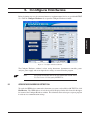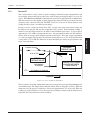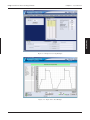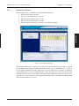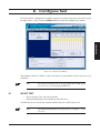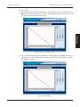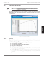
1
M-TEST 5.0 Motor Testing Software User’s Manual Purchase Record Please record all model numbers and serial numbers of your Magtrol equipment, along with the general purchase information. The model number and serial number can be found on either a silver identification plate or white label affixed to each unit. Refer to these numbers whenever you communicate with a Magtrol representative about this equipment. Model Number: _____________________________ Serial Number: _____________________________ Purchase Date: _____________________________ Purchased From: _____________________________ While every precaution has been exercised in the compilation of this document to ensure the accuracy of its contents, Magtrol, Inc. assumes no responsibility for errors or omissions. Additionally, no liability is assumed for any damages that may result from the use of the information contained within this publication. COPYRIGHT Copyright ©2005–2006 Magtrol, Inc. All rights reserved. Copying or reproduction of all or any part of the contents of this manual without the express permission of Magtrol is strictly prohibited. TRADEMARKS National Instruments™, LabVIEW™, FieldPoint™, NI-DAQ™ and NI-488.2™ are trademarks of National Instruments Corporation. Microsoft® and Windows® are registered trademarks of Microsoft Corporation. Pentium® and Celeron® are registered trademarks of Intel Corporation. Second Edition, revision A – May 2006 Safety Precautions 1. Make sure that all Magtrol dynamometers and electronic products are earth-grounded, to ensure personal safety and proper operation. 2. Check line voltage before operating electronic equipment. 3. Make sure that dynamometers and motors under test are equipped with appropriate safety guards. i Revisions To This Manual The contents of this manual are subject to change without prior notice. Should revisions be necessary, updates to all Magtrol User’s Manuals can be found at Magtrol’s web site at www.magtrol.com/support/manuals.htm. Please compare the date of this manual with the revision date on the web site, then refer to the manual’s Table of Revisions for any changes/updates that have been made since this edition. REVISION DATE Second Edition, revision A – May 2006. Corresponds to Release 1.03 and later versions of M-TEST 5.0 TABLE OF REVISIONS Date Edition Change National Instruments™ NI-DAQ™mx Data Acquisition Driver 05/16/06 2nd Edition, rev. A Software is now required for ALL M-TEST 5.0 installations. Replaced Advantech PCI-1760 relay actuator card with National 04/28/06 Second Edition Instruments NI 6521 relay actuator card. 04/28/06 Second Edition Added NI-DAQ Driver Software installation instructions. 04/28/06 Second Edition Added Pre-Load option to dynamometer configuration. Added Magtrol Free-Run Speed Sensor (FR 10) as instrument 04/28/06 Second Edition type option for Channel 2 (TSC2). 04/28/06 Second Edition Added 1, 2 and 6-bit Encoder options to Channel 1 configuration. 04/28/06 Second Edition Added Include Equipment List field under Data Logging. 04/28/06 Second Edition Added Locked Rotor parameter under Ramp Test configuration. 04/28/06 Second Edition 11/23/05 First Edition 11/23/05 First Edition 11/23/05 First Edition 11/23/05 First Edition 11/23/05 First Edition 11/23/05 First Edition Preliminary 08/10/05 Manual, Rev. A National Instruments USB-9211 changed to USB-9211A Added optional Advantech PCI-1760 relay actuator card to control motor power via M-TEST 5.0. Exit tab added. Current data filename and path is now displayed in test result windows. Changed PID setting options/values. Added PID scaling commands. New PID adjustment procedures. Correction: Step 7 of software and driver installation procedure. ii Section(s) 2.1, 2.3 1.4, 2.1, 2.3, 2.6. 5.4 2.3 5.2 5.2.3 5.2.3 8.2 8.4 1.2, 1.4, 2.1, 2.5.2, 5.5.2 1.4, 2.1, 2.2, 2.5, 5.4 chapter 17 11.0, 12.0, 13.0 9.1 9.1 9.2, 9.3 2.2 Table of Contents SAFETY PRECAUTIONS.......................................................................................................................... I REVISIONS TO THIS MANUAL................................................................................................................ II REVISION DATE.................................................................................................................................................................. II TABLE OF REVISIONS....................................................................................................................................................... II TABLE OF CONTENTS........................................................................................................................... III TABLE OF FIGURES.........................................................................................................................................................VII PREFACE................................................................................................................................................. IX PURPOSE OF THIS MANUAL..........................................................................................................................................IX WHO SHOULD USE THIS MANUAL...............................................................................................................................IX MANUAL ORGANIZATION..............................................................................................................................................IX CONVENTIONS USED IN THIS MANUAL.....................................................................................................................XI 1. INTRODUCTION.................................................................................................................................. 1 1.1 1.2 1.3 1.4 ABOUT M-TEST 5.0.................................................................................................................................................. 1 SYSTEM REQUIREMENTS...................................................................................................................................... 1 SOFTWARE FEATURES............................................................................................................................................ 2 1.3.1 New Features of M-TEST 5.0....................................................................................................................... 2 1.3.2 Other Features............................................................................................................................................... 2 DATA SHEET.............................................................................................................................................................. 3 2. INSTALLATION.................................................................................................................................... 6 2.1 2.2 INSTALLATION PROCEDURE................................................................................................................................. 6 INSTALLING M-TEST 5.0 PRODUCT SOFTWARE AND DRIVERS.................................................................... 6 2.2.1 Creating A Desktop Shortcut......................................................................................................................... 7 2.3 INSTALLING NI-DAQMX DATA ACQUISITION DRIVER SOFTWARE............................................................. 8 2.4 INTERFACE SETUP................................................................................................................................................... 9 2.4.1 Installing the GPIB Board............................................................................................................................. 9 2.4.2 Configuring GPIB Devices.......................................................................................................................... 10 2.4.3 RS-232 Serial Interface............................................................................................................................... 10 2.5 SENSOR INPUT/TEMPERATURE MEASUREMENT.......................................................................................... 11 2.5.1 National Instruments FieldPoint.................................................................................................................. 11 2.5.2 National Instruments USB-9211A.............................................................................................................. 12 2.6 NATIONAL INSTRUMENTS NI 6521 RELAY ACTUATOR CARD..................................................................... 13 2.6.1 Installing the Relay Card............................................................................................................................. 13 3. M-TEST 5.0 INTERFACE................................................................................................................... 14 3.1 3.2 STARTING M-TEST 5.0........................................................................................................................................... 14 M-TEST WINDOWS................................................................................................................................................. 14 3.2.1 Start.............................................................................................................................................................. 15 3.2.2 Configure Hardware.................................................................................................................................... 15 3.2.3 Display......................................................................................................................................................... 15 3.2.4 Configure Test.............................................................................................................................................. 15 3.2.5 Adjust PID................................................................................................................................................... 15 3.2.6 Test.............................................................................................................................................................. 15 3.2.7 View Data.................................................................................................................................................... 15 3.2.8 5-Axis Graph............................................................................................................................................... 15 3.2.9 1-Axis Graph............................................................................................................................................... 15 iii Table of Contents 3.3 Magtrol M-TEST 5.0 Motor Testing Software 3.2.10 Compare...................................................................................................................................................... 15 3.2.11 Reports......................................................................................................................................................... 15 3.2.12 Security........................................................................................................................................................ 16 3.2.13 Exit.............................................................................................................................................................. 16 NAVIGATING M-TEST 5.0...................................................................................................................................... 16 3.3.1 Help............................................................................................................................................................. 16 3.3.2 Tabs.............................................................................................................................................................. 16 3.3.3 Text Boxes................................................................................................................................................... 16 3.3.4 Indicators..................................................................................................................................................... 17 3.3.5 Inaccessible Controls................................................................................................................................... 17 4. START................................................................................................................................................ 18 4.1 LOGIN....................................................................................................................................................................... 18 4.1.1 Logout.......................................................................................................................................................... 19 4.2 SELECT LANGUAGE.............................................................................................................................................. 19 4.2.1 Additional Languages.................................................................................................................................. 19 4.3 CURRENT SETUP FILENAME............................................................................................................................... 20 4.3.1 Save Setup................................................................................................................................................... 20 4.4 CURRENT DATA FILENAME................................................................................................................................. 20 4.4.1 Save Data..................................................................................................................................................... 20 4.5 CURRENT REPORT FILENAME............................................................................................................................ 20 4.5.1 Save Report.................................................................................................................................................. 20 5. CONFIGURE HARDWARE................................................................................................................ 21 5.1 5.2 5.3 5.4 5.5 5.6 GPIB DEVICE/ADDRESS DETECTION................................................................................................................ 21 DYNAMOMETER CONTROLLER......................................................................................................................... 22 5.2.1 Alarms......................................................................................................................................................... 23 5.2.2 Load Defaults.............................................................................................................................................. 23 5.2.3 Channels...................................................................................................................................................... 24 POWER MEASUREMENT...................................................................................................................................... 26 POWER SUPPLY...................................................................................................................................................... 27 SENSOR INPUT....................................................................................................................................................... 28 5.5.1 Devce Selection........................................................................................................................................... 28 5.5.2 USB-9211A................................................................................................................................................. 28 5.5.3 FieldPoint TC.............................................................................................................................................. 29 SAVING THE HARDWARE CONFIGURATION................................................................................................... 30 5.6.1 Apply Settings............................................................................................................................................. 30 5.6.2 Save Setup................................................................................................................................................... 30 6. DISPLAY............................................................................................................................................ 31 6.1 6.2 DISPLAY SETUP...................................................................................................................................................... 31 6.1.1 Motor Parameters........................................................................................................................................ 31 6.1.2 Navigation................................................................................................................................................... 32 SAVE SETUP............................................................................................................................................................ 32 7. TEST SELECTION............................................................................................................................. 33 7.1 7.2 7.3 7.4 RAMP TESTING ..................................................................................................................................................... 33 7.1.1 Measuring Methods..................................................................................................................................... 33 7.1.2 Average-D/U (Down/Up)............................................................................................................................ 34 7.1.3 Dynamic-CF................................................................................................................................................ 36 CURVE TESTING..................................................................................................................................................... 38 MANUAL TESTING................................................................................................................................................. 40 PASS/FAIL TESTING............................................................................................................................................... 40 7.4.1 Pass/Fail Test Example................................................................................................................................ 41 iv Table of Contents Magtrol M-TEST 5.0 Motor Testing Software 8. CONFIGURE TEST............................................................................................................................ 45 8.1 8.2 8.3 8.4 8.5 SELECT TEST ......................................................................................................................................................... 45 DATA LOGGING...................................................................................................................................................... 46 CURVE/MANUAL TEST PARAMETERS.............................................................................................................. 47 8.3.1 Control Data Table....................................................................................................................................... 50 RAMP TEST PARAMETERS................................................................................................................................... 51 8.4.1 Special Data Points Table............................................................................................................................ 54 PASS/FAIL TEST PARAMETERS........................................................................................................................... 55 8.5.1 Pass/Fail Control Table................................................................................................................................ 56 9. ADJUST PID...................................................................................................................................... 57 9.1 9.2 9.3 PID PARAMETERS.................................................................................................................................................. 58 ADJUSTING THE CONTROLLER FOR A CURVE OR PASS-FAIL TEST.......................................................... 59 ADJUSTING THE CONTROLLER FOR A RAMP TEST...................................................................................... 62 10. TEST................................................................................................................................................. 65 10.1 CONFIGURE HARDWARE..................................................................................................................................... 65 10.2 CONFIGURE DISPLAY........................................................................................................................................... 65 10.3 CONFIGURE AND RUN TEST............................................................................................................................... 66 10.3.1 Curve Test.................................................................................................................................................... 66 10.3.2 Ramp Test.................................................................................................................................................... 67 10.3.3 Manual Test................................................................................................................................................. 67 10.3.4 Pass/Fail Test............................................................................................................................................... 68 10.4 VIEW TEST DATA................................................................................................................................................... 68 10.4.1 Tabular Display............................................................................................................................................ 68 10.4.2 Graphical Display........................................................................................................................................ 68 10.5 CONFIGURE REPORT............................................................................................................................................. 68 10.6 SAVE TEST DATA.................................................................................................................................................... 69 11. VIEW DATA....................................................................................................................................... 70 11.1 SAVE TEST DATA.................................................................................................................................................... 70 11.2 PRINT TEST DATA.................................................................................................................................................. 71 12. 5-AXIS GRAPH................................................................................................................................ 72 12.1 SELECT PLOTTED PARAMETERS....................................................................................................................... 72 12.2 SAVE DATA.............................................................................................................................................................. 72 13. 1-AXIS GRAPH................................................................................................................................ 73 13.1 SELECT PLOTTED PARAMETERS....................................................................................................................... 73 13.2 SAVE DATA.............................................................................................................................................................. 73 14. COMPARE........................................................................................................................................ 74 14.1 LOAD DATA............................................................................................................................................................. 74 14.2 SELECT PLOTTED PARAMETERS....................................................................................................................... 74 15. REPORTS........................................................................................................................................ 75 15.1 15.2 15.3 15.4 CONFIGURE REPORT............................................................................................................................................. 76 VIEW REPORT......................................................................................................................................................... 77 SAVE REPORT.......................................................................................................................................................... 77 PRINT REPORT........................................................................................................................................................ 77 v Table of Contents Magtrol M-TEST 5.0 Motor Testing Software 16. SECURITY....................................................................................................................................... 79 16.1 PASSWORD ADMINISTRATION........................................................................................................................... 79 16.1.1 Password Visible.......................................................................................................................................... 80 16.1.2 Disable Password Protection....................................................................................................................... 80 17. EXIT.................................................................................................................................................. 81 18. TROUBLESHOOTING...................................................................................................................... 82 APPENDIX A: GRAPH TOOLS.............................................................................................................. 83 A.1 PLOT LEGEND......................................................................................................................................................... 83 A.2 AUTO SCALE........................................................................................................................................................... 85 A.3 CURVE FIT............................................................................................................................................................... 85 A.3.1 Polynomial Order........................................................................................................................................ 85 A.4 GRAPH PALETTE.................................................................................................................................................... 86 A.4.1 Cursor Movement Tool................................................................................................................................ 86 A.4.2 Zoom............................................................................................................................................................ 86 A.4.3 Panning Tool................................................................................................................................................ 87 A.5 CURSOR LEGEND................................................................................................................................................... 87 A.5.1 Cursor Movement Selector......................................................................................................................... 88 A.5.2 Formatting Button....................................................................................................................................... 88 A.5.3 Lock Button................................................................................................................................................. 88 A.5.4 Cursor Mover............................................................................................................................................... 88 A.6 HIDE GRID............................................................................................................................................................... 89 APPENDIX B: PID/SCALING................................................................................................................ 90 B.1 B.2 B.4 ABOUT THE PID LOOP.......................................................................................................................................... 90 B.1.1 P (Proportional Gain).................................................................................................................................. 90 B.1.2 I (Integral).................................................................................................................................................... 90 B.1.3 D (Derivative).............................................................................................................................................. 90 HOW THE PID LOOP WORKS............................................................................................................................... 91 B.2.1 PID Scaling for Hysteresis, Eddy-Current and Powder Brake Dynamometers.......................................... 91 B.2.2 Speed Correction for WB (Eddy-Current Brake) Dynamometers............................................................... 92 B.2.3 Equations..................................................................................................................................................... 92 DYNAMIC PI SCALING.......................................................................................................................................... 92 B.4.1 Setting the Dynamic PI for Ramp Down..................................................................................................... 93 APPENDIX C: SOFTWARE REVISION HISTORY................................................................................ 95 INDEX...................................................................................................................................................... 96 SERVICE INFORMATION....................................................................................................................... 99 RETURNING MAGTROL EQUIPMENT FOR REPAIR AND/OR CALIBRATION....................................................... 99 Returning Equipment to Magtrol, Inc. (United States).............................................................................................. 99 Returning Equipment to Magtrol SA (Switzerland).................................................................................................. 99 vi Table of Contents Magtrol M-TEST 5.0 Motor Testing Software TABLE OF FIGURES 2. INSTALLATION Figure 2–1 Figure 2–2 Figure 2–3 Figure 2–4 Figure 2–5 Figure 2–6 M-TEST 5.0 Software Installation.............................................................................................................6 Installation Complete................................................................................................................................7 NI-DAQmx Data Acquisition Driver Software Installer............................................................................8 NI-488.2 Getting Started Wizard...............................................................................................................9 NI-488.2 Troubleshooting Wizard..............................................................................................................9 GPIB Configuration................................................................................................................................10 3. M-TEST 5.0 INTERFACE Figure 3–1 Start Window...........................................................................................................................................14 Figure 3–2 Inaccessible Controls Example...............................................................................................................17 4. START Figure 4–1 Start Window...........................................................................................................................................18 Figure 4–2 Password Prompt.....................................................................................................................................18 5. CONFIGURE HARDWARE Figure 5–1 Configure Hardware Window..................................................................................................................21 6. DISPLAY Figure 6–1 Display Setup Window.............................................................................................................................31 7. TEST SELECTION Figure 7–1 Average-D/U Motor Curve Before Inertial Cancellation........................................................................34 Figure 7–2 Average-D/U Motor Curve......................................................................................................................35 Figure 7–3 Correction Factor Calculation................................................................................................................36 Figure 7–4 Dynamic-CF Test Before Inertial Cancellation.......................................................................................37 Figure 7–5 Dynamic-CF Test.....................................................................................................................................37 Figure 7–6 Torque Curve Setu Example....................................................................................................................39 Figure 7–7 Torque Curve Test Example.....................................................................................................................39 Figure 7–8 Pass/Fail Test Example............................................................................................................................41 Figure 7–9 Pass/Fail Test Run Window......................................................................................................................42 Figure 7–10 Pass/Fail Test Results Window...............................................................................................................42 Figure 7–11 Failed Test Example...............................................................................................................................43 Figure 7–12 Microsoft Excel Data File.....................................................................................................................44 8. CONFIGURE TEST Figure 8–1 Figure 8–2 Figure 8–3 Figure 8–4 Figure 8–5 Configure Test Window............................................................................................................................45 Curve Test Setup Window........................................................................................................................47 Manual Test Setup Window......................................................................................................................47 Ramp Test Setup Window.........................................................................................................................51 Pass/Fail Test Setup Window...................................................................................................................55 9. ADJUST PID Figure 9–1 Adjust PID Window.................................................................................................................................57 Figure 9–2 Curve (no I or D).....................................................................................................................................60 Figure 9–3 Curve (P at 25%).....................................................................................................................................60 Figure 9–4 Curve (with P and I)................................................................................................................................61 Figure 9–5 Matched Curve........................................................................................................................................61 Figure 9–6 Ramp (with bump and offset)...................................................................................................................62 Figure 9–7 Ramp (with bump)...................................................................................................................................63 Figure 9–8 Ramp (no bump but unstable)..................................................................................................................63 Figure 9–9 Ramp (no bump and stable).....................................................................................................................64 Figure 9–10 Final Ramp............................................................................................................................................64 10. TEST Figure 10–1 Test Window Example............................................................................................................................66 vii Table of Contents Magtrol M-TEST 5.0 Motor Testing Software 11. VIEW DATA Figure 11–1 View Data Window.................................................................................................................................70 Figure 11–2 Configure Print Window........................................................................................................................71 12. 5-AXIS GRAPH Figure 12–1 5-Axis Graph Window............................................................................................................................72 13. 1-AXIS GRAPH Figure 13–1 1-Axis Graph Window............................................................................................................................73 14. COMPARE Figure 14–1 Compare Window..................................................................................................................................74 15. REPORTS Figure 15–1 Reports Window.....................................................................................................................................75 Figure 15–2 Display Report.......................................................................................................................................77 Figure 15–3 Sample Motor Test Report.....................................................................................................................78 16. SECURITY Figure 16–1 Password Administration Window.........................................................................................................79 17. EXIT Figure 17–1 Exit Window...........................................................................................................................................81 APPENDIX A: GRAPH TOOLS Figure A–1 M-TEST Graph........................................................................................................................................83 APPENDIX B: PID/SCALING Figure B–1 Figure B–2 Figure B–3 Figure B–4 System Block Diagram............................................................................................................................91 Ramp Down Low I..................................................................................................................................93 Ramp Down High I.................................................................................................................................93 Ramp Down Dynamic I...........................................................................................................................94 viii Preface PURPOSE OF THIS MANUAL This manual contains information required for installation and general use of Magtrol’s M‑TEST 5.0 Motor Testing Software. To achieve maximum capability and ensure proper use, please read this manual in its entirety before operating. Keep the manual in a safe place for quick reference whenever a question should arise. WHO SHOULD USE THIS MANUAL This manual is intended for those operators in need of a software program to complement their Magtrol test equipment setup. The setup may include any of the following Magtrol products: • Hysteresis, Eddy-Current or Powder Brake Dynamometer (HD, WB or PB) • In-Line Torque Transducer (TM, TMB or TMHS) • Power Analyzer (Model 5100, 5300, 6510, 6510e, 6530 or 6550) • Dynamometer Controller (Model DSP6000, DSP6001, 5240 or 4629B) Optional auxiliary instrumentation can also be used. A DC power supply may be used in place of a power analyzer for reading back amps and volts. However, this is not recommended because readings will be less accurate and data transfer rates will be substantially slower. MANUAL ORGANIZATION This section gives an overview of the structure of the manual and the information contained within it. Some information has been deliberately repeated in different sections of the document to minimize cross-referencing and to facilitate understanding through reiteration. The structure of the manual is as follows: Chapter 1: INTRODUCTION – Contains the technical data sheet for M-TEST 5.0 and highlights the new features of the software. Chapter 2: INSTALLATION – Provides general installation instructions for M-TEST 5.0 software; GPIB interface board; FieldPoint temperature measurement hardware; and National Instruments relay actuator PCI card. Chapter 3: M-TEST 5.0 INTERFACE – Provides instruction for M-TEST 5.0 startup and navigation. Includes a brief overview of the software capabilities. Chapter 4: START – Provides instruction for logging in/out, selecting language and loading/ saving M-TEST files. Chapter 5: CONFIGURE HARDWARE – Contains the information needed to set up M‑TEST 5.0 software with details pertaining to the testing instruments, controller, power analyzer, power supply and temperature measurement hardware being utilized in the test configuration. Chapter 6: DISPLAY – Provides instruction for selecting motor parameters to be tested. Chapter 7: TEST SELECTION – Describes the different testing methods available in M‑TEST 5.0 and provides all the information needed to make a test selection. ix Preface Magtrol M-TEST 5.0 Motor Testing Software Chapter 8: CONFIGURE TEST – Provides information required to set up M-TEST 5.0 for the type of test to be performed. Chapter 9: ADJUST PID – Contains instruction for adjusting proportional gain, integral and derivative (PID) values of the dynamometer controller for a ramp, curve or pass/fail test. Chapter 10: TEST – Provides step-by-step instructions for setting up and running a basic curve, ramp, manual and pass/fail test from beginning to end. Chapter 11: VIEW DATA – Provides instructions for viewing, saving and printing test data in tabular format. Chapter 12: 5-AXIS GRAPH – Contains general information for viewing test data in a multiplot graph. Chapter 13: 1-AXIS GRAPH – Contains general information for viewing test data in up to 3 separate single-plot graphs. Chapter 14: COMPARE – Provides instructions for displaying two different sets of test data simultaneously. Chapter 15: REPORTS – Provides instructions for creating, viewing, saving and printing test reports. Chapter 16: SECURITY – Provides instructions for enabling and setting up optional password protection. Chapter 17: EXIT – Provides instructions for quitting M-TEST 5.0 Chapter 18: TROUBLESHOOTING – Provides solutions to common problems encountered during setup and testing. Appendix A: GRAPH TOOLS – Contains detailed information on formatting and navigating the graphs in M-TEST 5.0. Appendix B: PID/SCALING – Describes the function of the PID loop and provides instructions for PID/PI scaling and speed correction. Appendix C: SOFTWARE REVISION HISTORY – Displays timeline of all M‑TEST 5.0 releases, including brief descriptions of changes involved with each revision. x Preface Magtrol M-TEST 5.0 Motor Testing Software CONVENTIONS USED IN THIS MANUAL The following symbols and type styles may be used in this manual to highlight certain parts of the text: Note: This is intended to draw the operator’s attention to complementary information or advice relating to the subject being treated. It introduces information enabling the correct and optimal functioning of the product to be obtained. Caution:This is used to draw the operator’s attention to information, directives, procedures, etc. which, if ignored, may result in damage being caused to the material being used. The associated text describes the necessary precautions to take and the consequences that may arise if the precautions are ignored. WARNING! THIS INTRODUCES DIRECTIVES, PROCEDURES, PRECAUTIONARY MEASURES, ETC. WHICH MUST BE EXECUTED OR FOLLOWED WITH THE UTMOST CARE AND ATTENTION, OTHERWISE THE PERSONAL SAFETY OF THE OPERATOR OR THIRD PARTY MAY BE PUT AT RISK. THE READER MUST ABSOLUTELY TAKE NOTE OF THE ACCOMPANYING TEXT, AND ACT UPON IT, BEFORE PROCEEDING FURTHER. xi 1.1 ABOUT M-TEST 5.0 Magtrol’s M-TEST 5.0 is a state-of-the-art motor testing program designed for use with Windows® 2000/XP operating systems for PC-based data acquisition. Used in conjunction with Magtrol’s Motor Testing Equipment, M-TEST 5.0 is equipped with ramp, curve and manual testing capabilities to help determine the performance characteristics of a motor under test. The software also performs pass/fail testing for production line and inspection applications. The data generated can be stored, displayed and printed in tabular or graphic formats, and is easily imported into a spreadsheet. MTEST 5.0 is ideal for simulating loads, cycling the unit under test and motor ramping. Magtrol can also make custom modifications to the software to meet your specific motor testing needs. M-TEST 5.0 is equipped to work in conjunction with any of the following Magtrol motor testing instruments: • Dynamometer Controller (DSP6001/6000, 5240, 4629B) • Hysteresis, Eddy-Current or Powder Dynamometer (HD, WB, PB) • In-Line Torque Transducer (TM, TMB, TMHS) • Power Analyzer (6530, 6510e, 6510, 6550, 5100, 5300) Note: A DC power supply may be used in place of a power analyzer for reading back amps and volts. However, this is not recommended because readings will be less accurate and data transfer rates will be substantially slower. Written in LabVIEW™, M-TEST 5.0 has the flexibility to test a variety of motors in a multitude of configurations. If you have a specialized test that you wish to perform, contact Magtrol Technical Assistance at 716-668-5555. 1.2 SYSTEM REQUIREMENTS Recommended: • Personal computer with Intel® Pentium® III or Celeron® 600 MHz processor (or equivalent) • Microsoft® Windows® 2000/XP • 128 MB of RAM • 1 GB of available hard drive space • VGA color monitor with minimum screen resolution of 1024 × 768 • National Instruments™ PCI-GPIB card • RS-232 serial interface can be used, instead of GPIB card, for interfacing with Magtrol DSP6000 or DSP6001 controllers • National Instruments™ FieldPoint™ or USB-9211A hardware: Required only if temperature testing (sensor input) function will be used 1 GENERAL INFORMATION 1. Introduction Chapter 1 – Introduction SOFTWARE FEATURES 1.3.1 New Features of M-TEST 5.0 Magtrol’s M-TEST 5.0 Software is an improved motor testing program that replaces M-TEST 4.0. The program is comprised of many new features that make it unique. • New Graphical User Interface: Tabbed pages for quick navigation • Temperature/Sensor Measurement: Temperature testing capabilities are now included in standard program • Multiple Language Support: Switch to/from English, French, German or Spanish at any point during the program. Additional language dictionaries can be created/edited by the user. • More Graphing Options: Display up to three different 1-axis graphs (one for each tested parameter) in the same window • Compare Test Data: Overlay data from two separate tests on the same graph • Rapid Graph Plotting: Change both the X- and Y-axis to display additional test curves, without having to exit the graph • Cursor Tools: Obtain the X and Y coordinates of any point on a curve; Magnify any section of the graph • Simplified PID Scaling: New slider controls set both coarse and fine gain adjustment simultaneously • Single or Multi-User Login: Enable password protection and assign user access rights for specific windows and program functions • Loads Most Recently Saved Setup File Upon Startup: Provides valuable time savings for users who repeatedly run only one type of test • Automatic GPIB Device/Address Detection: Displayed within program to easily check communication parameters 1.3.2 Other Features • Multiple Testing Options: Ramp, Curve, Manual and Pass/Fail • Displays 22 Tested and Calculated Parameters • Three-Phase Power Analyzer Data Acquisition • Motor Shaft Direction Indicator • IEEE-488 and RS-232 Interface • Automatically Loads Dynamometer Default Values • Dynamic PID Scaling • PID Adjustment Routines • Multiplot or Single Plot Graphical Display • Curve Fitting • Customized Reports • Save/Load Setup Function 2 GENERAL INFORMATION 1.3 Magtrol M-TEST 5.0 Motor Testing Software Chapter 1 – Introduction Magtrol M-TEST 5.0 Motor Testing Software M-TEST 5.0 Data Sheet M-TEST 5.0 Motor Testing Software NEW FEATURES WITH M-TEST 5.0 New Graphical User Interface:Tabbedpagesforquick navigation. • Temperature/Sensor Measurement:Temperaturetesting capabilitiesarenowincludedinstandardprogram. • Multiple Language Support:Switchto/fromEnglish,French, GermanorSpanishatanypointduringtheprogram.Additional languagedictionariescanbecreated/editedbytheuser. • More Graphing Options: Displayuptothreedifferent1-axis graphs(oneforeachtestedparameter)inthesamewindow. • Compare Test Data: Overlaydatafromtwoseparatetestson thesamegraph. • Rapid Graph Plotting:ChangeboththeX-andY-axisto displayadditionaltestcurves,withouthavingtoexitthegraph. • Cursor Tools:ObtaintheXandYcoordinatesofanypointon acurve.Magnifyanysectionofthegraph. • Simplified PID Scaling:Newslidercontrolssetbothcoarse andfinegainadjustmentsimultaneously. • Single or Multi-User Login: Enablepasswordprotectionand assignuseraccessrightsforspecificprogramfunctions. • Loads Most Recently Saved Setup File Upon Startup: Providesvaluabletimesavingsforuserswhorepeatedlyrun onlyonetypeoftest. • Automatic GPIB Device/Address Detection: Displayed withinprogramtoeasilycheckcommunicationparameters. • M-TEST 5.0 Hardware Configuration M-TEST 5.0 Graphical Data Output DESCRIPTION SENSOR INPUT MEASUREMENT Magtrol’snewM-TEST5.0isastate-of-the-artmotortesting programforPC(Windows®2000/XP)baseddataacquisition. UsedwithaMagtrolProgrammableDynamometerController, M-TEST5.0workswithanyMagtrolDynamometerorInLineTorqueTransducertohelpdeterminetheperformance characteristicsofamotorundertest.Upto22parametersare calculatedanddisplayedutilizingM-TEST5.0’sfeature-rich testingandgraphingcapabilities. Temperaturemeasurement—previouslyanadd-onfeaturethat hadtobepurchasedseparately—isnowincludedinM-TEST5.0. Up to 32 thermocouples or analog sensors can be read and monitoredduringamotortest.Heatrisecurvesonthebearings, windings and housing of a motor can be performed and air flow/exhaustefficienciescanbemeasuredwithanairtoolor internal combustion engine. M-TEST 5.0, with its complete dynamometercontrol,evenallowsforsensormeasurementwhile performingloadsimulationfordutycycleandlifetesting. AnintegralcomponentofanyMagtrolMotorTestSystem, M-TEST5.0performsramp,curve,manualandpass/failtests inamannerbestsuitedtotheoverallefficiencyofthetestrig. WritteninLabVIEW™,M-TEST5.0hastheflexibilityto testavarietyofmotorsinamultitudeofconfigurations.The datageneratedfromthisuser-friendlyprogramcanbestored, displayedandprintedintabularorgraphicalformats,andis easilyimportedintoaspreadsheet. APPLICATIONS M-TEST5.0—besidesbeingwell-suitedforsimulatingloads, cyclingtheunitundertestandmotorramping—isalsoidealfor productionlineandinspectionapplications,duetoitspass/fail testfunction.Anothertime-savingfeature,thatengineering labs will benefit from, is the ability to duplicate tests and runthemautomatically.Thisversatileprogramisextremely valuabletoanyoneinvolvedinmotortesting. Magtrolcanalsomakecustommodificationstothesoftware tomeetadditionalmotortestingrequirements. www.magtrol.com 1 3 GENERAL INFORMATION 1.4 M DATAAGTROL SHEET Chapter 1 – Introduction Magtrol M-TEST 5.0 Motor Testing Software M-TEST 5.0 STANDARD FEATURES • • • Multiple Testing Options: Ramp: Selectfromaveragerampdown/uporramp downwithinertiacorrectionfactor.Also allowsextrapolationoffree-runandlockedrotordata,plusinterpolationofspecific speedortorquedatapoints. Curve: Testspeed,torque,amps,wattsinput,watts outputandopenloopparameters.Capableof adjustingsamplingrateandusingsteporramp fromoneloadpointtothenext. Manual: Runstestfromfrontpanelofthe DynamometerControllerwhilecomputer acquiresdata.Allowsadjustmentof samplingrate. Pass/Fail: Checksamps,inputwatts(withoptional PowerAnalyzer),speed,torqueandoutput wattsagainstuser-definedvalues. Displays 22 Tested and Calculated Parameters: Torque,speedandauxiliaryinputaredisplayedfrom theDSP6000/6001,5240or4629BController;amps, voltsandwattsfroman(optional)poweranalyzer. Calculatedvaluesincludinghorsepower,efficiency, powerfactor,outputwattsandtimecanalsobe displayed. Three-Phase Power Analyzer Data Acquisition: Obtaindataoneachindividualphaseand/orthesum usedinthechosenparameters(amps,volts,inputwatts andpowerfactor). • • • • • • • • • Motor Shaft Direction Indicator:Indicatesifthe motoristurningclockwiseorcounterclockwise. IEEE-488 and RS-232 Interface:Computerinterface withNationalInstruments™PCI-GPIB.RS-232 availablewithDSP6001andDSP6000only. Automatic Load Defaults Option:Downloadstesting instrumentparametersbasedonmodelnumber. Dynamic PID Scaling:Providesconsistentcontrolloop resultsthroughoutmotorspeedrangeduringramptest (forDSP6001only). PID Adjustment Routines:Helpsadjustthesystem forrampandstepfunctions. Graphing Capabilities:Displayupto5testcurvesina singlegraphorviewas(upto3)separate1-axisgraphs; easy-to-readcoloredandlabeledplotswithseveralgraph formattingoptions;manualorautoscaling. Curve Fitting:Acurvefittingroutinecanbeapplied tomostmotortestcurves.Rawdataandcurvefitdata canalsobedisplayedsimultaneously. Customized Reports:Allowsusertoproducea one-pagemotortestsummary,whichcanincludethe motor'sserialnumber;maximumtorque,speed,power andcurrentvalues;operatorname;timeanddateof test;motordirection;32datapoints;andanX-Yplot. Save/Load Setup Function:Testprocedure configurationsmaybestoredandrecalledusing standardWindows®filestructure. SYSTEM CONFIGURATION AMagtrolDynamometerprovidesmotorloadingwithaMagtrol ProgrammableDynamometerControlleractingastheinterface betweenthePCrunningM-TEST5.0andthedynamometer. If motor electrical parameters are to be measured or used to determineloadpoints,aMagtrolPowerAnalyzerisalsorequired. Interfacingbetweenthecomputerandelectronicinstrumentation isviatheNationalInstruments™PCI-GPIBcardorRS-232 serialinterface(whenusingaDSP6000orDSP6001). Shaded area represents additional components and setup required for Temperature Testing. Select from FP or USB options. GPIB Cable M-TEST 5.0 Serial Port Serial Cable Power Supply -OR- USB Port USB Cable 2 GPIB Cable MODEL DSP6001 DYNAMOMETER CONTROLLER DSP6001 Programmable Controller PC GPIB Card M-TEST5.0isequippedtoworkinconjunctionwithanyof thefollowingMagtrolmotortestinginstruments: • DynamometerController(DSP6001/6000,5240,4629B) • Hysteresis,Eddy-CurrentorPowderDynamometer (HD,WB,PB) • In-LineTorqueTransducer(TM,TMB,TMHS) • PowerAnalyzer(6530,6510e,6510,6550,5100,5300) FP-1000 network interface & Thermocouples (8 per module, 32 max.) MODEL 6510 POWER ANALYZER 6510e or 6530 Power Analyzer (optional) Motor Power Source FP-TC thermocouple input module USB-9211A 4-channel to motor isolated input module 4 Thermocouples Motor Under Test } 4 HD Hysteresis Dynamometer M AGTROL GENERAL INFORMATION Specifications Chapter 1 – Introduction Magtrol M-TEST 5.0 Motor Testing Software GENERAL INFORMATION Ordering Information M-TEST 5.0 SYSTEM REQUIREMENTS • • • • • PersonalcomputerwithIntel®Pentium®IVprocessor (orequivalent) Microsoft®Windows®2000/XP 1GBofRAM 1.6GBofavailableharddrivespace VGAcolormonitorwithminimumscreenresolutionof 1024×768 • NationalInstruments™PCI-GPIBcard(availablefrom Magtrol) • RS-232serialinterfacecanbeused,insteadofGPIB card,forinterfacingwithMagtrolDSP6000or DSP6001Controllers • NationalInstruments™FieldPoint™orUSB-9211A hardware:Requiredonlyiftemperaturetesting/sensor inputfunctionwillbeused SYSTEM OPTIONS AND ACCESSORIES CATEGORY DESCRIPTION FieldPoint 8-Channel Isolated Input Module (FP-TC-120-X), Network Interface (FP-1000), 120 V Power Supply and Serial Cable TEMPERATURE FieldPoint 8-Channel Isolated Input Module (FP-TC-120-X), TESTING Network Interface (FP-1000), 240 V Power Supply and Serial Cable HARDWARE Additional FieldPoint 8-Channel Thermocouple Module (includes mounting base) USB 4-Channel Isolated Input Module (USB-9211A) and USB Cable (1 m) CONTROLLERS High Speed Programmable Dynamometer Controller Hysteresis Dynamometers Eddy-Current Dynamometers TESTING INSTRUMENTS Powder Brake Dynamometers In-Line Torque Transducers High Speed Single-Phase Power Analyzer POWER ANALYZERS High Speed Three-Phase Power Analyzer Closed-Loop Speed Control and Power Supply Power Supply for WB & PB Dynamometers series 2.7 and 43 POWER SUPPLIES Power Supply for WB & PB Dynamometer series 65, 115 and 15 Power Amplifier—required for all HD-825 Dynamometers MISC Torque/Speed Conditioner GPIB Interface Card (PCI) CARDS Relay Actuator Card (for controlling motor power via M-TEST 5.0) GPIB Cable, 1 meter CABLES GPIB Cable, 2 meters Torque Transducer Connector Cable MODEL / PART # HW-TTEST-FP HW-TTEST-FP-A 004968 HW-TTEST-USB DSP6001 HD series WB series PB series TM/TMHS/TMB series 6510e 6530 6100 DES 310 DES 311 5241 TSC 401 73-M023 73-M052 88M047 88M048 ER 113/01 Forinformationonthemostcurrentsoftwarereleaseavailable,refertoMagtrol'sWebsiteat www.magtrol.com/motortesting/mtest.htm Due to the continual development of our products, we reserve the right to modify specifications without forewarning. MAGTROL INC 70 Gardenville Parkway Buffalo, New York 14224 USA Phone: +1 716 668 5555 Fax: +1 716 668 8705 E-mail: [email protected] MAGTROL SA Route de Montena 77 1728 Rossens / Fribourg, Switzerland Phone: +41 (0)26 407 3000 Fax: +41 (0)26 407 3001 5 E-mail: [email protected] Subsidiaries in: Great Britain Germany • France China • India Worldwide Network of Sales Agents MTEST-US 04/10 www.magtrol.com 2. Installation 2.1 INSTALLATION PROCEDURE The remainder of this chapter will provide specific installation instructions for each component of the system. 2.2 INSTALLING M-TEST 5.0 PRODUCT SOFTWARE AND DRIVERS 1. Exit all other programs before installing M-TEST 5.0. 2. Insert the M-TEST 5.0 CD in your CD-ROM drive. The M-Test 5.0 Installation Wizard will begin automatically. Note: If AutoRun is disabled on your computer, the installation process must be started manually. On the taskbar, click the Start button, and then click Run. Click Browse to locate the CD-Rom drive where the M-TEST 5.0 installation CD is inserted. From the M-TEST CD root directory, select setup.exe then click Open. 3. Click Next. Figure 2–1 M-TEST 5.0 Software Installation 4. Select the Destination Folder then click Next. The default is C:\Program Files\M-Test 5.0\. To install into a different folder, click the Browse button and select another folder. 6 GETTING STARTED The general installation order is as follows. 1. Install M-TEST 5.0 product software and drivers. 2. Install National Instruments™ NI-DAQ™mx Data Acquisition Software. 3. Install PCI-GPIB interface board. (If only using a DSP6000/6001, the RS-232 serial interface may be used.) 4. Install National Instruments™ FieldPoint™ or USB-9211A if using temperature measurement/sensor input function. 5. Install (optional) National Instruments™ NI 6521 relay actuator card to control motor power via M‑TEST 5.0. Chapter 2 – Installation Magtrol M-TEST 5.0 Motor Testing Software 5. After installation is complete, the (MS-DOS) command prompt will open and run in the background. The M-TEST 5.0 Setup window will indicate that the program has been successfully installed. GETTING STARTED Figure 2–2 Installation Complete 6. Click Finish. The required M-TEST 5.0 drivers will be automatically installed at this time. National Instruments’ Measurement & Automation Explorer software will also be automatically installed. Note: Measurement & Automation Explorer (MAX) provides access to your National Instruments GPIB and FieldPoint devices. With MAX, you can: • Configure your National Instruments hardware and software • Create and edit channels, tasks, interfaces, scales and virtual instruments • Execute system diagnostics • View devices and instruments connected to your system • Update your National Instruments software 7. While these remaining two processes are running, the Installer Information message box may appear notifying that “You must restart your system for the configuration changes made to M-TEST 5.0 to take effect.” If this message box appears, click Cancel. (Your system will re-boot later – see step 8.) 8. After the installation of the M-TEST 5.0 drivers and NI Measurement & Automation software is complete, your computer will automatically re-boot. Please note that this may take several minutes. 2.2.1 Creating A Desktop Shortcut For easy access to M-TEST 5.0, a shortcut can be placed on your computer desktop. 1. Start Windows Explorer and locate the directory where M-TEST 5.0 is installed. 2. Click the M-Test.exe file and drag it to your desktop. 3. To access M-TEST 5.0, double-click the shortcut and the program will automatically start. 7 Chapter 2 – Installation 2.3 Magtrol M-TEST 5.0 Motor Testing Software INSTALLING NI-DAQmx DATA ACQUISITION DRIVER SOFTWARE The National Instruments™ NI-DAQ™mx Data Acquisition Driver Software must be installed at this time. 1. Insert the National Instruments NI-DAQmx for Windows CD in your CD-ROM drive. The CD is supplied with M-TEST 5.0. The software can also be downloaded from National Instruments’ Web site at www.ni.com. Note: The NI-DAQ 8.x installer should open automatically. If not, select Start >> Run. Enter x:\autorun.exe, where x is the letter of the CD drive. Figure 2–3 NI-DAQmx Data Acquisition Driver Software Installer 2. Click Install NI-DAQmx / VI Logger. The “Welcome” message will appear and the installer will begin initializing. This will take a few moments. 3. When this step is complete, the Product Information dialog box will appear. After reading the displayed information, click Next. 4. Select the Destination Folder then click Next. The default is C:\Program Files\ National Instruments\. To install into a different folder, click the Browse button and select another folder. 5. The Features dialog box will appear. All of the features required to install/run M-TEST 5.0 should be selected by default. It is recommended to keep the default settings. 6. Click Next. 7. The License Agreement will appear. In order to proceed, the displayed license(s) must be accepted by selecting the corresponding option button. 8. Click Next. 9. The Start Installation dialog box will appear. Review the displayed summary then click Next. 10. The installer has been configured. Click Next to begin installation. 11. After several minutes, the Installation Complete dialog box will appear. Click Next. 12. When prompted to restart, shut down or restart later, select Shut Down (in preparation for interface board installation). Note: If you choose to “restart later”, please note that you must restart your computer before running any National Instruments software. 8 GETTING STARTED Chapter 2 – Installation Magtrol M-TEST 5.0 Motor Testing Software 2.4 INTERFACE SETUP The GPIB interface board (National Instruments™ PCI-GPIB), purchased through Magtrol or directly from National Instruments, must be installed at this time. The National Instruments PCI-GPIB is a high-performance plug-and-play IEEE 488 interface for PCs and workstations equipped with PCI expansion slots. 2.4.1 Note: If only using a DSP6001 or DSP 6001 Dynamometer Controller in the test configuration, the RS-232 serial interface may be used. Installing the GPIB Board 1. Shut down your computer. 2. Install the PCI-GPIB controller board in an available PCI expansion slot according to National Instruments’ user documentation. 3. Turn on your computer. The new hardware will automatically be installed and the NI‑488.2 Getting Started Wizard will appear. Figure 2–4 NI-488.2 Getting Started Wizard 4. Click Verify your hardware and software installation. The NI‑488.2 Troubleshooting Wizard will appear. Figure 2–5 NI-488.2 Troubleshooting Wizard 5. When the software, hardware and interfaces have been verified, as shown in Figure 2–4 NI-488.2 Troubleshooting Wizard, click Exit. 6. Select the Do not show at Windows startup check box. 7. Click Exit to close the NI‑488.2 Getting Started Wizard. 9 GETTING STARTED Chapter 2 – Installation 2.4.2 Magtrol M-TEST 5.0 Motor Testing Software Configuring GPIB Devices 1. Run the GPIB Configuration utility in Measurement and Automation Explorer. On the taskbar, click the Start button, and then click Run. Click Browse to locate C:\Program Files\National Instruments\NI-488.2\Bin\GpibConf.exe, then click Open. GETTING STARTED Figure 2–6 GPIB Configuration 2. Under Device Name, select DEV9. 3. Set DEV9 Attributes to the following: Note: 4. 5. 6. 7. 8. 9. 2.4.3 The only DEV attributes that need to be changed are those that are outlined below. All other settings should remain in their original format. a. Under Termination Methods: 1.) Select the Terminate Read on EOS check box. 2.) Change EOS Byte to “10”. b. Select the Readdress check box. Select DEV12. Set DEV12 Attributes by repeating steps 3a–3b. Select DEV14. Set DEV12 Attributes by repeating steps 3a–3b. Click OK. The GPIB device configuration is complete. RS-232 Serial Interface M-TEST 5.0 will communicate with the DSP6000/6001 Dynamometer Controller using an RS‑232 Serial Interface. Connection diagrams and instructions can be found in the following User’s Manuals: • DSP6000 – Section 5.7–Select the Baud Rate for the RS-232 Interface • DSP6001 – Section 8.2–About the RS-232 Interface 10 Chapter 2 – Installation Magtrol M-TEST 5.0 Motor Testing Software 2.5 SENSOR INPUT/TEMPERATURE MEASUREMENT 2.5.1 National Instruments FieldPoint Features: • 8 thermocouple inputs per module × 4 modules = 32 thermocouples maximum • Built-in voltage isolation on all channels • Filtering reduces electrical noise associated with attaching thermocouples to motors • Connects to computer through RS-232 serial port 2.5.1.1 Installing Hardware 1. Shut down your computer. 2. Connect the FP-1000 RS-232/RS-485 network interface to the FP-TC 8-channel thermocouple input module(s). 3. Connect a power supply to the network interface with the positive lead to the V terminal and the negative lead to the C terminal. 4. Connect the serial cable from the network interface to COM1 serial port on the computer. 2.5.1.2 Thermocouple Connections 1. Install thermocouples beginning at Channel 0. Following is a list of channels with the corresponding terminals. Channels 0 1 2 3 4 5 6 7 2.5.1.3 IN+ (positive terminal) 1 3 5 7 9 11 13 15 IN(negative terminal) 2 4 6 8 10 12 14 16 Thermocouple Type and Temperature Unit Changes 1. On the taskbar, click Start button and then click Explore to open Windows Explorer. 2. Locate directory where M-TEST 5.0 is installed (default: C:\ProgramFiles\M-Test 5.0\). 3. Double-click MT5CFG.iak to open FieldPoint Explorer. 4. Expand Devices and Interfaces folder. 5. Right-click FP@com1. 6. Select Find Devices. 11 GETTING STARTED M-TEST 5.0 allows the user to perform temperature measurement testing. The feature provides complete dynamometer control, allowing for temperature measurement while performing load simulation for duty cycle and life testing. The options, which may be purchased from either Magtrol or National Instruments, include: • National Instruments™ FieldPoint™ • National Instruments™ USB-9211A Chapter 2 – Installation Magtrol M-TEST 5.0 Motor Testing Software Note: If all channels use the same thermocouple type, deselect One channel at a time check box and click the All button. This will allow changes to be made to all the channels at once. 15. Click Apply. Note: If additional TC modules are installed, steps 8 through 16 will need to be repeated for modules FP-TC-120-2, FP-TC-120@3 and FPTC-120@4 (where applicable). 16. Close FieldPoint Explorer. The program will prompt you to “save changes to untitled.” 17. Select Yes. 18. Close Windows Explorer. 2.5.2 National Instruments USB-9211A Features: • 4 thermocouple inputs • Built-in isolation on all channels • Connects to computer through USB port 2.5.2.1 Installing Hardware 1. Plug in USB cable. 12 GETTING STARTED 7. Expand FP@com1 folder. 8. Expand FP-1000@0Bank. 9. Click FP-TC-120@X (X represents 1, 2, 3 or 4—the module to be configured). 10. Click Channel Configuration tab. 11. Select check box for the channel to be configured. 12. Select temperature range in either °F or °C. 13. Under Channel Attributes, select thermocouple type in Value box. 14. Repeat steps 11-13 for each channel. Chapter 2 – Installation Magtrol M-TEST 5.0 Motor Testing Software 2.6 NATIONAL INSTRUMENTS NI 6521 RELAY ACTUATOR CARD As an option, Magtrol offers the National Instruments™ NI 6521 relay actuator card for controlling motor power via M-TEST 5.0. The relay actuator, used in conjunction with a contactor, serves as an ON/OFF switch for supplying power to the motor under test. The National Instruments NI- 6521 relay actuator card is rated at 150 V AC/DC, 2 amps, 60 VA max. Please refer to the included manufacturer’s specifications for additional ratings. 2.6.1 Installing the Relay Card 1. Shut down your computer. 2. Install the National Instruments NI 6521 card in an available PCI expansion slot according to National Instruments’ user documentation. 3. Turn on your computer. If installation was successful, Windows will detect the device and display the Found New Hardware message. 4. Connect the motor contactor to relay 0 (R0) of the NI 6521 connector, following the pin diagram in the user documentation. 13 GETTING STARTED When the relay actuator is enabled (see Section 5.4–Power Supply), M-TEST 5.0 automatically closes the relay at the beginning of each test. Relay closure allows power to be applied to the contactor which, in turn, applies power to the motor. When the test is completed, the relay automatically opens and the contactor and motor are switched off. 3. M-TEST 5.0 Interface 3.1 STARTING M-TEST 5.0 From the taskbar, click Start, point to Programs >> M-Test 5.0, then click M-Test. If you created a shortcut on your desktop (see Section 2.1.1–Creating A Shortcut), double-click the desktop icon and the program will automatically start. The Start window will appear. GETTING STARTED Figure 3–1 Start Window 3.2 M-TEST WINDOWS The following outline is a representation of how M-TEST 5.0 is organized and shows, at a quick glance, where all the main features are located within the program. The 12 navigation tabs displayed at the top of the M-TEST 5.0 screen are purposely in the same order (sequentially from left to right) as a standard motor test procedure. Following is a brief description of the functions of each area. Note: For detailed explanations of every button and control of each window (program area), please refer that window’s corresponding chapter in this manual. 14 Chapter 3 – M-TEST 5.0 Interface Magtrol M-TEST 5.0 Motor Testing Software Start • Log in and log out (if password protection enabled). • Select language from English, French, Spanish, German or user-created dictionary. • Load/save current setup file, data file and report file. 3.2.2 Configure Hardware • Search for and display GPIB addresses of devices communicating with M-TEST 5.0. • Configure the system for all connected hardware including: dynamometer controller, power analyzer, power supply and sensor input device. • Load default testing instrument parameters based on model number. 3.2.3 Display • Select parameters to be tested and displayed. 3.2.4 Configure Test • Select test type and set up corresponding test parameters. • Enable and set up data logging to automatically store acquired data at the end of each test. 3.2.5 Adjust PID • Adjust PID (proportional gain, integrative and derivative) settings and scaling on the DSP6000/6001 Controller. 3.2.6 Test • • Run test. Graphically display live test data. 3.2.7 View Data • Display test data in a tabular (spreadsheet) format with option to print. 3.2.8 5-Axis Graph • Display up to five different test parameters on the same graph. 3.2.9 1-Axis Graph • Display up to three separate 1-axis graphs (one for each tested parameter) in the same window. 3.2.10 Compare • Overlay data from two separate (saved) tests on the same graph. 3.2.11 Reports • Configure, view, print and save test reports. 15 GETTING STARTED 3.2.1 Chapter 3 – M-TEST 5.0 Interface Magtrol M-TEST 5.0 Motor Testing Software 3.2.12 Security • Enable/disable password protection. • Set up multiple users. • Assign user access rights for specific windows. 3.2.13 Exit • NAVIGATING M-TEST 5.0 The following details will assist in navigating through M-TEST 5.0. 3.3.1 Note: A mouse must be used to maneuver through the program. Help For help with any item, right-click the control (button, text box, indicator, list, etc.). A drop-down menu will appear. Click Description and Tip and a message box will appear with useful information about the item in question. 3.3.2 Tabs Navigate from window to window by clicking the tabs at the top of the screen. 3.3.3 Text Boxes For text boxes, there are two ways to make a selection: 1. Click inside the box and scroll down to the item of choice. 2. Click the up and down arrows to the left of the box until the desired option is reached. 3.3.3.1 Numeric Entries For text boxes requiring a numeric value, simply click inside the box and type the desired value. To overwrite an existing entry, click and drag the pointer across the field and then type the new value. Note: When using the up and down arrows, the program will not allow the numbers to leave the specified range. If typing a value, any number can be used but those out of range will be ignored. 16 GETTING STARTED 3.3 Exit M-TEST 5.0. Chapter 3 – M-TEST 5.0 Interface Magtrol M-TEST 5.0 Motor Testing Software 3.3.4 Indicators When an indicator is illuminated in green, that function is enabled. If the indicator is dimmed (dark gray), the correspnding function is disabled. Inaccessible Controls Controls (buttons, text boxes, etc.) will be available as needed. If there is no selection needed for a specific item, the control will be dimmed and no access may be gained to that control. For example, when “None” is selected as the Device in the Power Measurement section of the Configure Hardware window, there is no further input needed. Therefore, the remainder of the controls in that section are inaccessible to the user (a seen in the figure below). Figure 3–2 Inaccessible Controls Example 17 GETTING STARTED 3.3.5 4. Start The Start window is the first window that appears when M-TEST 5.0 is launched. GETTING STARTED Figure 4–1 Start Window 4.1 LOGIN If password protection is enabled (see Chapter 16 – Security), each user must log in to access M‑TEST 5.0 program windows. 1. Click Login. The password prompt will appear. Figure 4–2 Password Prompt 18 Chapter 4 – Start Magtrol M-TEST 5.0 Motor Testing Software 2. Type your designated user name and password. 3. Click Login (button inside password prompt dialog box). After providing this information, you will have access to the program windows assigned to you in the current security setup. 4.1.1 Logout 4.2 Note: When M-TEST 5.0 is closed, the current user is automatically logged out. SELECT LANGUAGE Select the language you would like to work with while using M-TEST 5.0. Click inside the Select Language box, then click on the desired language. Standard options include: English, German, Spanish and French. 4.2.1 Note: The language can be changed at any time while running the program by simply returning to the Start window and selecting a new language. Additional Languages Additional language dictionaries can be created by the user by editing the Language File.csv file (located in the M-TEST 5.0 program folder) in any spreadsheet program. To add a new language, simply add a new column to the spreadsheet and manually enter translations for every term, using the English column (column B) as a template. Note: If, for any reason, you need to obtain the default Language File that was installed with M-TEST 5.0, you can download it from Magtrol’s web site at http://www.magtrol.com/support/downloads.htm 19 GETTING STARTED To change users, the current user must first log out. 1. Return to the Start window and click Login. 2. When the password prompt appears, click Logout. Chapter 4 – Start 4.3 Magtrol M-TEST 5.0 Motor Testing Software CURRENT SETUP FILENAME By default, M-TEST 5.0 automatically loads the most recently saved Setup file upon startup. To load another previously saved Setup file, click Load Setup and select the appropriate file in the Load Setup File dialog box. 4.3.1 Save Setup 4.4 CURRENT DATA FILENAME To load previously saved test data, click Load Data and select the appropriate file in the Load Data File dialog box. 4.4.1 Save Data To save test data as a file that can be recalled later by M-TEST 5.0, click Save Data. The Save As dialog box will appear. Select the desired folder and type the desired file name (which will be saved with an .mdf file extension). The data is then saved as a tab-delimited file that can be imported into any spreadsheet program. The Save Data button is also conveniently located in the following windows: View Data, 5-Axis Graph and 1-Axis Graph. 4.5 CURRENT REPORT FILENAME To load a previously saved report, click Load Report and select the appropriate file in the Load Report File dialog box. 4.5.1 Save Report The current report can be saved by clicking Save Report. The Save As dialog box will appear. Select the desired folder and type the desired file name (which will be saved with an .rpt file extension). The Save Report button is also located in the Reports window. 20 GETTING STARTED The current test configuration can be saved by clicking Save Setup. The Save As dialog box will appear. Select the desired folder and type the desired file name (which will be saved with an .msf file extension). 5. Configure Hardware Before beginning any test, the connected motor test equipment must first be set up within M-TEST 5.0. Click the Configure Hardware tab to open the Configure Hardware window. TEST SETUP Figure 5–1 Configure Hardware Window The Configure Hardware window is where testing instrument, dynamometer controller, power analyzer, power supply and sensor input device settings are entered into the program. 5.1 Note: For specific instructions on how to enter information into M‑TEST 5.0, see Section 3.3–Navigating M-TEST 5.0. GPIB DEVICE/ADDRESS DETECTION To search for GPIB devices connected to the motor test system, and available to M-TEST 5.0, click Find Devices. The GPIB address of each device will be displayed in the table located in the upper left corner of the Configure Hardware window. This eliminates the need to open a separate program in order to view communication settings. 21 Chapter 5 – Configure Hardware 5.2 Magtrol M-TEST 5.0 Motor Testing Software DYNAMOMETER CONTROLLER Used with a Magtrol DSP6000/6001, 5240 or 4629B Programmable Dynamometer Controller, M‑TEST 5.0 provides the control of any Magtrol Dynamometer or Torque Transducer and runs test sequences in a manner best suited to the overall accuracy and efficiency of the Magtrol Motor Test System. In this section, specifications for each testing instrument are set up for each channel. Alarms are also enabled or disabled at this time. Control Model Function Selects the controller model being used. 22 GPIB and Serial (RS-232) 1 to 32 NOTE: Click Find Devices to display the controller’s GPIB address in the Device/Address table located in the upper left corner of the Configure Hardware window. See Section 5.1– GPIB Device/Address Detection 1 to 4 300, 600, 1200, 2400, 4800, 9600 and 19200 Yes and No TEST SETUP Display Torque Selects the torque units. NOTE: This may be the same as the dynamometer units, or converted to other units. Interface Type Selects the method of interfacing between the controller and the computer. GPIB Address Sets the GPIB address for the controller. NOTE: It must match the address that has been set up through the controller. DSP6000/6001: front panel COM SETUP menu 5240 and 4629B: rear panel, next to the GPIB connector Serial Port Selects the computer port number when using serial communication. Baud Rate Sets the baud rate for serial communications. (Applies only to DSP6000/6001.) NOTE: This value must match the baud rate set up through the front panel COM SETUP menu on the DSP controller. Acquire Aux/ If using the auxiliary input on the TSC2 DSP6000/6001 to read an additional parameter, set this control to “Yes” to have the data displayed and stored with other acquired data. NOTE: Proper scaling must be set up from the front panel AUX SETUP menu on the DSP controller. Options/Values 5240/4629B, DSP6000 and DSP6001 NOTE: The DSP6000, 5240 and 4629B are only compatible with Magtrol Hysteresis Dynamometers. The DSP6001 is compatible with Magtrol Hysteresis, Eddy-Current, and Powder Brake Dynamometers, Magtrol In-Line Torque Transducers and auxiliary instrumentation. oz.in, oz.ft, lb.in, lb.ft, g.cm, kg.cm, mN.m, cN.m and N.m Chapter 5 – Configure Hardware Magtrol M-TEST 5.0 Motor Testing Software Control Active Channel Pre-Load 5.2.1 Function Selects the channel on which the control loop is closed when using a DSP6001. Options/Values Channel 1 or Channel 2 NOTE: Certain load device/ dynamometer combinations will not permit changing channels. See Section 5.2.3–Channels. Writes an open-loop value of current to 0.00 to 99.99% the dynamometer brake. NOTE: Acts to preload the brake, limiting motor speed without interfering with the PID loop. Alarms Only for use with the DSP6001 Dynamometer Controller. Function Enables the airflow alarm function for (HD) Hysteresis Dynamometers, indicating a lack of air flow. Waterflow Enables the waterflow alarm function for Alarm (WB) Eddy-current and (PB) Powder Brake dynamometers, indicating a lack of water flow. External Alarm Enables the external alarm function for any dynamometer, indicating a problem based on additional user input. 5.2.2 Enable and Disable Enable and Disable For more information on Alarms, see Chapter 6 – Alarm System in the DSP6001 Dynamometer Controller User’s Manual. Load Defaults • Loads default values for all parameters from the M-TEST Defaults.txt file after the type and model of testing instrument(s) has been selected. • Click Load Defaults and the values will automatically update. 5.2.2.1 Note: Options/Values Enable and Disable Note: This step must be completed for the testing instrument torque units to be programmed properly into the controller. If necessary, once the defaults are set, they can be adjusted. Updated M-TEST Defaults File The M-TEST Defaults file is subject to change as ratings on Magtrol’s Motor Test Equipment change. If you have purchased any Magtrol Dynamometers or Torque Transducers since initially installing M-TEST 5.0, visit www.magtrol.com/support/downloads.htm on Magtrol’s Web site to ensure that you have the most recent M-TEST Defaults.txt file available. Simply click the link to connect you directly or type the Web address into your browser. Please feel free to contact our sales department at 1-716-668-5555, if you should have any questions or concerns. 23 TEST SETUP Control Airflow Alarm Chapter 5 – Configure Hardware 5.2.3 Magtrol M-TEST 5.0 Motor Testing Software Channels M-TEST 5.0 channels are used for multiple testing instrument connections. If using a DSP6001 Dynamometer Controller, there can be up to 2 testing instrument connections. Any Magtrol dynamometer or brake can be connected to Channel 1 (TSC1). Channel 2 (TSC2) can only support a Magtrol Eddy-Current (WB) or Powder Brake (PB) Dynamometer; Magtrol In-Line Torque Transducer (TM); a Magtrol Free-Run Speed Sensor (FR 10); or auxiliary instrumentation. If using a 5240, 4629B or DSP6000 Dynamometer Controller, the default is set to Channel 1 (TSC1) and only a Hysteresis (HD) Dynamometer may be used. Control Instrument Type Model Tandem Encoder Quadrature Input Torque Filter Options/Values For Channel 1 (TSC1): Hysteresis Dynamometer (HD) Eddy-Current Dynamometer (WB) Powder Brake Dynamometer (PB) Brake For Channel 2 (TSC2): Auxiliary Eddy-Current Dynamometer (WB) Powder Brake Dynamometer (PB) In-Line Torque Transducer (TM) Free-Run Speed Sensor (FR 10) If using a brake and Magtrol In-Line Torque HB Hysteresis Brake Transducer in a cross loop function, WB Eddy-current Brake selects the type of brake connected to the PB Powder Brake Brake Output or Supply 1 of the controller. Applies to TSC1 only. Selects the specific model number of the The available model numbers will testing instrument. be listed, depending upon the Instrument Type selected. NOTE: Once the model is selected, click Load Defaults at the bottom of the window to update the parameters for that model. This step must be performed for the testing instrument torque units to be programmed properly in the controller. If it is necessary, once the defaults are set, they can be adjusted. If a tandem dynamometer is being used, Enable and Disable this function must be enabled. Selects the encoder type being used. 1, 2, 6, 20, 30, 60, 600 and 6000‑bit NOTE: Some models may have dual encoders for normal and low speed operation. In this situation, select the encoder currently in use. If the dynamometer has a low speed Enable or Disable quadrature encoder installed, the speed signal may be smoothed substantially by enabling this feature. NOTE: This applies only to 600- and 6000bit encoders that have both channels wired to the DSP6001 controller. Applies digital filtering to the torque signal 3, 10, 25 and 50 Hz cutoff input. frequencies Select Off to disable filtering. 24 TEST SETUP Brake Type Function Selects the type of loading device or dynamometer connected to the channel(s) (TSC1 and TSC2) of the controller. Chapter 5 – Configure Hardware Magtrol M-TEST 5.0 Motor Testing Software Control Nominal Speed 25 Options/Values 0 to 99,999 0 to 99,999 0 to 10,000 0 to 99,999 0 to 10,000 0 to 99,999 0 to 99,999 The value should be entered as the ratio from the motor shaft to the gearbox output shaft (in an x:1 ratio). For example: If the motor shaft spins at 3600 rpm and the gearbox output shaft spins at 2 rpm, the ratio entered should be 1800. TEST SETUP Function For WB and PB dynamometers, this is the maximum speed at rated torque. NOTE: Exceeding the nominal speed will cause the dissipated power to be greater than the dynamometer’s rating. Max Speed Maximum no-load speed at which the dynamometer can be run without physical damage. Max Speed Maximum speed that may be used under Excited any load condition. Max Power Maximum rated power (in kilowatts) that the dynamometer can dissipate without causing physical damage. Max Torque Maximum torque rating of the dynamometer. Torque/Aux This is the torque value at 5 volts output Scale Factor for WB & PB dynamometers and TM transducers; and the scale factor for the auxiliary input. Scale Factor This is the torque value at 5 volts output for WB and PB dynamometers. Gearbox Ratio If using a motor with a gearbox attached, the gearbox ratio may be entered here to give the true motor speed and torque. Otherwise, the dynamometer speed and torque will be displayed. NOTE: All parameters throughout the program will reflect the motor performance only. Chapter 5 – Configure Hardware 5.3 Magtrol M-TEST 5.0 Motor Testing Software POWER MEASUREMENT To read amps, volts, watts, power factor and system efficiency data, a separate device is needed CONTROL Device FUNCTION Selects the device used to read power data. NOTE: The DC power supply may be used to read back amps and volts if absolutely necessary. However, doing so will result in reduced accuracy and slower data transfer rates, which subsequently affects the number of data points acquired. Units Sets the power units that the 5100 is displaying. NOTE: This control only needs to be set if a Magtrol 5100 Power Analyzer with external shunt is being used. This is because some current ranges cause the 5100 to read consumed power in kilowatts. M-TEST 5.0 is configured to automatically record and display power in watts. As a result, if the 5100 is displaying power in kW, this control must be set to kW. External Shunt Enables the external shunt(s) connected to Yes and No the power analyzer (if applicable). 26 TEST SETUP GPIB Address Selects the corresponding GPIB address for the power measurement device. OPTIONS/VALUES • None • EMI • HP603xA • HP66xxA • Lambda Genesys • Power Ten • Sorensen DCS • Sorensen DHP • Xantrex XFR • Xantrex XDC • 5100 • 5300 (1 and 3 phase) • 6510 • 6510e • 6530: 1 ph. 2 w. 1 ph. 3 w. 3 ph. 3 w. 3 ph. 4 w. 3 ph. 3 v. 3 a. • 6550: 1 ph. 2 w. 1 ph. 3 w. 3 ph. 3 w. 3 ph. 4 w. 3 ph. 3 v. 3 a. • LMG310: 1 ph. 2 w. 3 ph. 4 w. 3 (2) ph. 3 w. 2 m. 3 ph. 3 w. 3 m. star 3 ph. 3 w. 3 m. delta • WT1600: 1 ph. 2 w. 1 ph. 3 w. 3 ph. 3 w. 3 ph. 4 w. 3 ph. 3 v. 3 a. 1 to 32 NOTE: Click Find Devices to display the device’s GPIB address in the Device/Address table located in the upper left corner of the Configure Hardware window. See Section 5.1–GPIB Device/Address Detection. Watts and kW Chapter 5 – Configure Hardware Magtrol M-TEST 5.0 Motor Testing Software 5.4 Shunt 1 Scaling Sets the scaling constant for the external shunt on phase 1. Shunt 2 Scaling Sets the scaling constant for the external shunt on phase 2. Shunt 3 Scaling Sets the scaling constant for the external shunt on phase 3. 0.0001 to 99999 NOTE: The constant is determined by dividing the full scale amps of the shunt by 50 mV 0.0001 to 99999 NOTE: The constant is determined by dividing the full scale amps of the shunt by 50 mV 0.0001 to 99999 NOTE: The constant is determined by dividing the full scale amps of the shunt by 50 mV POWER SUPPLY Note: Control Device “None” is defined as any AC or DC external power source not controlled by the system. “DC” is defined as a DC power source that is controlled by the system. Function Selects the type of power supply being used. NOTE: If running from AC lines, select “None” as your power supply. If using one of the mentioned DC power supplies, be sure that its GPIB address corresponds to what you have set in the GPIB Address control. GPIB Address Sets the GPIB address for the DC power supply. Voltage Set Current Set Relay Control Options/Values • None • AC Regulated (Staco MPA2) • EMI • HP603xA • HP66xxA • Lambda Genesys • Power Ten • Sorensen DCS • Sorensen DHP • Xantrex XFR • Xantrex XDC 1 to 32 NOTE: Click Find Devices to display the power supply’s GPIB address in the Device/ Address table located in the upper left corner of the Configure Hardware window. See Section 5.1–GPIB Device/ Address Detection Any Any Sets desired DC voltage. Sets to the maximum current that the DC power supply needs to deliver. Accessible when optional National Instruments Enabled and Disabled NI 6521 relay actuator card is installed. Automatically switches on the motor at the beginning of a test and, conversely, turns motor power off at test completion. See Section 2.6–National Instruments NI 6521 Relay Actuator Card for more information. 27 TEST SETUP Tells the system which DC power source is being used and sets the corresponding attributes. Chapter 5 – Configure Hardware 5.5 Magtrol M-TEST 5.0 Motor Testing Software SENSOR INPUT Up to 32 thermocouples or analog sensors can be read and monitored during a motor test. Heat rise curves on the bearings, windings and housing of a motor can be performed and air flow/exhaust efficiencies can be measured with an air tool or internal combustion engine. M‑TEST 5.0, with its complete dynamometer control, even allows for sensor measurement while performing load simulation for duty cycle or life testing. 5.5.1 Devce Selection Control Device Options/Values • None • USB-9211 • FieldPoint TC USB-9211A Control Function Thermocouple Selects type of thermocouple. Type Units Selects desired temperature unit for acquired/ displayed values. TC0 – TC3 Assigns a specific name/label to each thermocouple channel being used (TC0, TC1, TC2, TC3). 28 Options/Values J, K, N, R, S, T, B and E • Deg C • Deg F • Kelvins • Deg R • From Custom Scale Select checkbox next to each thermocouple channel being used. Type desired label (any string of alphanumeric characters, without spaces) in box to right. TEST SETUP 5.5.2 Function Selects the sensor input module. Chapter 5 – Configure Hardware Magtrol M-TEST 5.0 Motor Testing Software 5.5.3 FieldPoint TC Control Module Number Selection Hardware Labels Offset Options/Values 0, 1, 2 and 3 • None • FP Module 1 • FP Module 2 • FP Module 3 • FP Module 4 Assigns a specific name/label to each Select thermocouple channel thermocouple channel being used. in box to left (0 through 7). NOTE: To label another thermocouple channel, Type desired label (any string use the up and down arrows to select another of alphanumeric characters) in channel. box to right. Adjusts any error that may occur between Select thermocouple channel the M-TEST 5.0 reading and the reference in box to left (0 through 7). temperature. Enter desired gain in box to This control may also be used to compensate right. for filter loss if low pass filters are installed at all thermocouple inputs. NOTE: To set gain for another thermocouple channel, use the up and down arrows to select another channel. Adjusts any offset that may occur between Select thermocouple channel the M-TEST 5.0 reading and the reference in box to left (0 through 7). temperature. Enter desired offset in box to NOTE: To set offset for another thermocouple right. channel, use the up and down arrows to select another channel. 29 TEST SETUP Gain Function Assigns a number to each Fieldpoint module so that appropriate settings can be configured. NOTE: To configure another module, use the up and down arrows to select another module number. Selects installed Fieldpoint module(s) to be read during test. Chapter 5 – Configure Hardware Magtrol M-TEST 5.0 Motor Testing Software 5.6 SAVING THE HARDWARE CONFIGURATION 5.6.1 Apply Settings When finished configuring the hardware, click Apply Settings. 5.6.2 Note : This does not permanently save the current test configuration. See Section 5.6.2–Save Setup Save Setup Note: To save current test configuration as a new setup file, click Apply Settings then return to the Start window. Create a new setup file by clicking Save Setup under Current Setup Filename. See Section 4.3.1–Save Setup. 30 TEST SETUP The current test configuration is saved, overriding the current setup file that is loaded. If you do not wish to override the current setup file (after pressing Save Setup), click Cancel when prompted and read the note below. 6. Display Click the Display tab to open the Display Setup window. TEST SETUP Figure 6–1 Display Setup Window The Display Setup window is used to select the parameters that will be measured, displayed and graphed during a test. 6.1 DISPLAY SETUP 6.1.1 Motor Parameters Torque Amps 1 Volts 1 Input Watts 1 Power Factor 1 Speed Amps 2 Volts 2 Input Watts 2 Power Factor 2 Time Amps 3 Volts 3 Input Watts 3 Power Factor 3 Auxiliary Input Amps Sum Volts Sum Input Watts Sum Power Factor Sum Note: Output Watts Output Kilowatts Horsepower Efficiency Direction of Rotation The numbers refer to the phase of a three-phase system. If using a single-phase source, select an option with a “1”. 31 Chapter 6 – Display 6.1.2 Magtrol M-TEST 5.0 Motor Testing Software Navigation Move parameters between the Available and Selected columns by either using the arrow buttons or double-clicking an entry. • Use the >> button to move all Available parameters to the Selected column. • To reset (clear all Selected parameters), click the << button. • To select multiple items, hold down the CTRL key while clicking on the desired parameters. • To select multiple, consecutive items, hold down the SHIFT key while clicking the uppermost and bottommost desired parameters. 6.2 SAVE SETUP Note: To save current test/display parameters in a new setup file, first return to the Start window. Create a new setup file by clicking Save Setup under Current Setup Filename. See Section 4.3.1–Save Setup. 32 TEST SETUP The current test/display parameters are saved, overriding the current setup file that is loaded. If you do not wish to override the current setup file (after clicking Save Setup), click Cancel when prompted and read the note below. 7. Test Selection Before any further setup is completed, a test type must be chosen. M-TEST 5.0 offers four methods of testing: ramp, curve, manual and pass/fail. This chapter will provide all the information needed to make a test selection. 7.1 RAMP TESTING 7.1.1 Measuring Methods 7.1.1.1 Old Measuring Methods The time to accomplish this was excessive, causing the motors to heat up severely. While the method produced accurate data at each point, the drastic increases in temperature caused a shift in the curve and resulted in inaccurate data. 7.1.1.2 New Measuring Methods Methods were developed to quickly ramp a motor from free run to locked rotor, negating the heating effects. However, along with the ramping came inertial effects on the data. When a motor is accelerating or decelerating: Measured Torque = True Motor Torque ± Inertial Torque (stored energy) Unless inertial torque is excluded, motor performance data will be in error since the measured torque will vary in proportion to the rate of acceleration or deceleration. This type of error can produce startling results. For example, during rapid deceleration, system inertia can produce apparent efficiency greater than 1. This may occur as output power is divided by input power without extracting the stored energy of the system. M-TEST 5.0 provides two methods of measuring inertially compensated data: Average-D/U (Down/Up) and Dynamic-CF. 33 TEST SETUP Years ago, motor performance was determined by loading a motor to a specific speed and recording the torque data. This procedure was repeated at a number of points until sufficient data was acquired to construct a curve. Chapter 7 – Test Selection 7.1.2 Magtrol M-TEST 5.0 Motor Testing Software Average-D/U (Down/Up) When a motor is placed under controlled deceleration, the torque produced at any given point will be greater due to stored energy. When the motor is then accelerated, the torque produced will be less at any given point. If the deceleration and acceleration rates are equal, the corrected data is simply an average of the two curves. M‑TEST 5.0 accomplishes this by ramping the motor down to a user-defined minimum speed. Because of system limitations, any speed less than 150 rpm (with the standard 60-bit encoder) will cause the motor to ramp down to 150 rpm and then begin accelerating. The motor will continue the controlled ramp until it has reached free run or until it no longer exhibits acceleration. TEST SETUP Figure 7–1 Average-D/U Motor Curve Before Inertial Cancellation 34 Chapter 7 – Test Selection Magtrol M-TEST 5.0 Motor Testing Software If locked rotor is specified as a minimum speed, the controller will run a separate procedure immediately after the acceleration ramp that will quickly take the motor to stall and record the data. The amount of time to wait at stall before taking data is defined by the Locked Rotor Dwell control, found under Ramp Test Parameters in the Configure Test window. See Section 8.4–Ramp Test Parameters. Several seconds at locked rotor may be necessary for the system to stabilize. (With stored energy and the load cell acting as a spring, there may be some bounce). After acquiring the locked-rotor data the motor will accelerate to its free run speed. The inertially corrected curve is produced by matching a speed from the deceleration curve with the same speed from the acceleration curve, and averaging the associated torque data. This continues for every point on the curve. If no exact matching speed is found on the acceleration curve, the data will be interpolated to create a match. If requested, the locked-rotor point will be added to the end of the data array to construct the complete curve. TEST SETUP Figure 7–2 Average-D/U Motor Curve 35 Chapter 7 – Test Selection Dynamic-CF Since “inertial effect” is only a factor as speed is changing, and inertial torque is proportional to the rate of change, inertial value may be expressed as a unit of torque per change in rpm in a given period of time. The DSP6000 and DSP6001 accumulate data at intervals of approximately 10 milliseconds. With data rates this fast, the amount of speed change from reading to reading is too small to be used accurately in the correction. Therefore, M‑TEST 5.0 inserts a wait state of 100 ms between each reading in order to allow a reasonable speed change. DECELERATION SPEED vs. TORQUE CURVE DYNAMIC TORQUE VALUE FR } 0.75 OF FR STATIC TORQUE VALUE CF = 0 AVERAGE THE CHANGE IN SPEED BETWEEN THESE POINTS DIFFERENCE IN TORQUE DIFFERENCE IN TORQUE CHANGE IN SPEED TORQUE Figure 7–3 Correction Factor Calculation The test sequence is to ramp a motor down from its free-run speed to a user-specified minimum speed or maximum torque. The ramp is then terminated and the motor is allowed to accelerate. When the motor nears free-run speed, it is loaded to a static speed (approximately 75% of free run). When ten readings are acquired within ± 0.3% of the target speed, loading is removed and the motor may be turned off. The correction factor is then calculated. 36 TEST SETUP In order to create a torque correction factor (CF), a torque value equal to the inertial torque and the difference in rpm (per 100 ms) that created that value is needed. In the following example, a motor has been decelerated from free run (FR) to some minimum speed value. A speed equal to approximately 75% of FR is selected from the curve. One speed point on either side of that point is used to obtain an average speed change that produces that torque. That value is now programmed as a static speed point. We now have data from the deceleration curve at 75% of FR and data from a static point at 75% of FR. The difference in torque divided by the change in speed produces the torque correction factor. SPEED 7.1.3 Magtrol M-TEST 5.0 Motor Testing Software Chapter 7 – Test Selection Magtrol M-TEST 5.0 Motor Testing Software The correction can now be applied to the entire deceleration curve. For any point on the curve, the corrected torque is the measured torque minus the CF value times the speed difference between this point and the previous point. Tc = Tm [CF × (Sn-1 - Sn)] Tc = Corrected Torque Tm = Measured Torque CF = Correction Factor Note: Sn-1 = Prior Speed at Torque Point Sn = Corrected Speed at the Torque Point Because there is no deceleration at free run and locked rotor, torque correction is not applied to these points. Figure 7–5 Dynamic-CF Test 37 TEST SETUP Figure 7–4 Dynamic-CF Test Before Inertial Cancellation Chapter 7 – Test Selection 7.2 Magtrol M-TEST 5.0 Motor Testing Software CURVE TESTING M-TEST 5.0 can be used in a way that simulates complex load profiles. This may be for heat run or endurance testing, simulating a real life usage, or just for checking a few specific data points. Loading may be accomplished by closing a control loop on Speed, Torque, or Output Watts (plus Amps or Input Watts if a power analyzer is incorporated into the system). Because closed loop speed and torque are internal functions of the dynamometer controller, the control loops are very fast and highly controllable. The remaining functions use a routine in M‑TEST 5.0 to close the loop and provide control. These will not provide as tight of a control as the internal functions but they are quite satisfactory for most applications. Parameter Amps Input Watts Speed Torque Output Watts Free Run 0 0 99999 0 0 Locked Rotor 99999 99999 0 99999 99999 In the example illustrated in Figures 7–6 and 7–7, a torque curve test will be performed that will: 1. Ramp the torque from zero to 10 in 5 seconds. 2. Dwell at 10 for 5 seconds. 3. Step to 20 in zero seconds. 4. Dwell at 20 for 5 seconds. 5. Ramp to zero in 3 seconds. 6. Dwell at zero for 5 seconds. 7. Repeat the cycle (steps 1 – 6) a second time. 38 TEST SETUP Loading can be accomplished by either stepping or ramping to the desired point. If stepping to a load point is desired, enter a time of “0” (zero) for that point. If ramping to a load point is desired, enter the number of seconds (or minutes, depending on the timebase setting) for the controller to ramp from the starting point to the ending point. To remain at a fixed load for a period of time, use the same value for “From” and “To”. To obtain free-run or locked-rotor data, use the following values: Chapter 7 – Test Selection Magtrol M-TEST 5.0 Motor Testing Software TEST SETUP Figure 7–6 Torque Curve Setup Example Figure 7–7 Torque Curve Test Example 39 Chapter 7 – Test Selection 7.3 Magtrol M-TEST 5.0 Motor Testing Software MANUAL TESTING In this mode of operation, the computer is being used only as a data acquisition device. No control is performed by M-TEST 5.0. 7.4 PASS/FAIL TESTING Pass/Fail motor testing is well suited for production line and inspection applications. Up to five parameters—torque, speed, amps, output watts and (with optional power analyzer) input watts—can be tested simultaneously and checked against user-defined values, providing a quick pass or fail indication to the operator. Testing at free run and locked rotor can also be performed. To obtain free-run or locked-rotor data use the following values: Parameter Amps Input Watts Speed Torque Output Watts Free Run 0 0 99999 0 0 40 Locked Rotor 99999 99999 0 99999 99999 TEST SETUP With pass/fail testing, motors can be tested at specified load points. The user determines the length of time to hold at each particular load point. Loading can be accomplished by either stepping or ramping to the desired point. If stepping to a load point is desired, enter a time of “0” (zero) for that point. If ramping to a load point is desired, enter the number of seconds (or minutes, depending on the timebase setting) for the controller to ramp from the starting point to the ending point. To remain at a fixed load for a period of time, use the same value for “From” and “To”. Chapter 7 – Test Selection Magtrol M-TEST 5.0 Motor Testing Software 7.4.1 Pass/Fail Test Example In the example below, a Pass/Fail test will be performed that will: 1. Dwell at 0 torque for 2 seconds. 2. Step to 5 oz·in and dwell for 2 seconds. 3. Step to 10 oz·in and dwell for 2 seconds. 4. Step to 15 oz·in and dwell for 2 seconds. 5. Step to 20 oz·in and dwell for 2 seconds. (not shown in example) TEST SETUP Figure 7–8 Pass/Fail Test Example This example demonstrates a motor test that collects data from 5 different torque points—a typical test that might be run during incoming inspection or at the end of a production line. At each of the load points, information on amps, input watts, speed and output watts is gathered. A minimum and maximum value is given for each load point. A data directory (C:\test data) has been created containing two files where the data will be sent, depending on whether the motor passes (pass.xls) or fails (fail.xls). A serial number is also assigned to each motor with an automatic increment, which makes the information easy to track. 41 Chapter 7 – Test Selection Magtrol M-TEST 5.0 Motor Testing Software When the test is running, the data will appear as follows. TEST SETUP Figure 7–9 Pass/Fail Test Run Window Once the test is completed, a window will appear that indicates the results of the test. Figure 7–10 Pass/Fail Test Results Window 42 Chapter 7 – Test Selection Magtrol M-TEST 5.0 Motor Testing Software In this example, at least one parameter failed as indicated by the red FAIL bar above the table. Each failed parameter is highlighted in red. TEST SETUP Figure 7–11 Failed Test Example 43 Chapter 7 – Test Selection Magtrol M-TEST 5.0 Motor Testing Software The data from the passed test will be sent to the pass.xls file that was set up at the beginning of the test. TEST SETUP Figure 7–12 Microsoft Excel Data File The data file contains the date and time of the test, the serial number of the motors and the acquired data. The order in which the data is displayed from left to right is determined by the order of parameter selection in the Display window during initial setup. See Chapter 6–Display. 44 8. Configure Test Once the hardware configuration is complete and the test parameters have been selected, the actual test must now be set up. Click the Configure Test tab to open the Configure Test window. TEST SETUP Figure 8–1 Configure Test Window The Configure Software window is where the software is programmed for the type of test to be performed. Note: 8.1 For specific instructions on how to enter information into M‑TEST 5.0, see Section 3.3–Navigating M-TEST 5.0. SELECT TEST • • Selects the type of test you wish to perform. Options include Ramp, Curve, Manual and Pass/Fail tests. As different tests are selected, the required controls for that test will become active. Note: For detailed information on each type of test, see Chapter 7 – Test Selection. 45 Chapter 8 – Configure Test 8.2 Magtrol M-TEST 5.0 Motor Testing Software DATA LOGGING Data Logging allows M-TEST 5.0 to automatically store acquired data at the end of each test. Control Save Data Data Folder Serial Number Auto Increment Save Report Report Folder Operator Code Pass Filename Fail Filename Include Equipment List Options/Values Enabled (select check box) and Disabled (clear check box) Specifies the drive and directory for curve, Click Data Folder to access ramp and manual test data files. Save As dialog box. Open the NOTE: File names are automatically generated desired folder and click Select Cur Dir. from the serial number and saved with an .xls file extension. Records the serial number for generating data Enter the serial number for the log files and reports. first motor being tested. Increments the serial number by one integer at Enabled (select check box) the end of each test. and Disabled (clear check box) NOTE: If the serial number is alphanumeric, the software looks for the last alpha character in the string. If it is followed by a number, that number will be incremented by one at the end of the test. If no number follows the last alpha character, a number will be added and incremented after each test. Generates a custom printed report after each Enabled (select check box) curve, ramp or manual test. and Disabled (clear check box) NOTE: The report must be configured first, Refer to Chapter 15–Reports. Saves a custom report after each curve, ramp Enabled (select check box) or manual test, to be viewed or printed at a and Disabled (clear check box) later time. NOTE: The report must be configured first, Refer to Chapter 15–Reports. If Save Report is enabled, specifies the drive Click Data Folder to access and directory for report files. Save As dialog box. Open the NOTE: File names are automatically generated desired folder and click Select Cur Dir. from the serial number and saved with an .rpt file extension. Records the operator’s name, initials or ID Any number for saving/printing on the report. For pass/fail testing, specifies the file name and Click Pass File Folder to location for passed motor data. access Save As dialog box. Select the desired folder and NOTE: Pass data is save as a tab-delimited type the desired file name. file. NOTE: Save the file with a .txt or .xls extension for easy importing into a spreadsheet. For pass/fail testing, specifies the file name and Click Fail File Folder to location for failed motor data. access Save As dialog box. NOTE: Fail data is save as a tab-delimited file. Select the desired folder and type the desired file name. NOTE: Save the file with a .txt or .xls extension for easy importing into a spreadsheet. Inserts the Controller, Dynamometer, and Power Enabled (select check box) Analyzer models into the comments field. and Disabled (clear check box) 46 TEST SETUP Print Report Function Enables data logging function. Chapter 8 – Configure Test Magtrol M-TEST 5.0 Motor Testing Software 8.3 CURVE/MANUAL TEST PARAMETERS When Curve test is selected, the window will appear as follows. TEST SETUP Figure 8–2 Curve Test Setup Window When Manual test is selected, the window will appear as follows. Figure 8–3 Manual Test Setup Window 47 Chapter 8 – Configure Test Magtrol M-TEST 5.0 Motor Testing Software The following parameters may be used when setting up a Curve or Manual Test. Control Import from Spreadsheet Control Parameter Speed Range Sets the speed range for the dynamometer controller. NOTE: The value entered should be slightly greater than the free run speed of the motor. Adjusting the Speed Range properly will give the best dynamic range for the PID settings. This parameter is only used with a tandem dynamometer setup. Timebase Sets the timebase for all the time values in the control table. Sampling Rate Sets the time interval at which a data point will (sec) be sampled and stored. NOTE: When using the Manual Test and timed storage, the data will be stored automatically at the rate selected here. The fastest rate is 100 samples per second (0.01 s). Number of Cycles Selects the number of times to repeat the load cycle. 48 Options/Values N/A Amps 1, Amps 2, Amps 3, Amps Sum, Input Watts 1, Input Watts 2, Input Watts 3, Input Watts Sum, Speed, Torque, Output Watts and Open Loop. NOTE: Torque will be in the units previously selected in the Display Torque text box under Dynamometer Controller in the Configure Hardware window. For Amps and Input Watts control, the number refers to the phase of a three-phase system. If using a singlephase source, select an option with a “1”. 0 to 99999 Seconds and Minutes Any NOTE: The fastest rate allowed in a curve test is 10 samples per second (0.10 s). This rate is necessary in order to maintain accurate timing for the ramp and dwell parameters. If you wish to acquire data only at the end of each dwell period, type ”99999”. 1 to 32767 TEST SETUP Function Imports data from an external tab-delimited text file and displays it in the Control Data table above. Selects the desired parameter to be used as the control. NOTE: When controlling by Speed or Torque, the controller uses its internal circuitry to close the loop on the desired set point. The PID controls are fully active for system response tuning. However, when using Amps, Input Watts, or Output Watts control, the controller operates in an open loop mode and the loop is closed through the M-TEST 5.0 program. This means that the control loop will probably not be as tight as the Speed or Torque modes. The only system tuning control available is proportional gain. Chapter 8 – Configure Test Magtrol M-TEST 5.0 Motor Testing Software Control Maximum Brake Current Maximum Current Allows a maximum value to be set for current. NOTE: If the measured current exceeds the value set up by this control, the test in progress will abort. 49 Options/Values 0 to 99.99% Any NOTE: The temperature units are the same as what was selected in the hardware setup. For FieldPoint: Units are configured within FieldPoint Explorer. See Section 2.4.1.3– Thermocouple Type and Temperature Unit Changes. For USB-9211: Units are set up in the Configure Hardware window, under Sensor Input. Any TEST SETUP Maximum Temperature Function Sets the maximum amount of current necessary that will lock the rotor, if desired, during the test sequence. Different size dynamometers require different amounts of DC current to produce full torque, or enough torque to lock the rotor of a motor being tested. The hysteresis dynamometer’s rotor will become magnetized if current is applied while the shaft is not turning. This produces residual magnetism, also known as a bump. If too much current is applied, the bump may be sufficiently large as to not allow the motor to begin rotating again. NOTE: If locked rotor is not desired, this control is irrelevant. Allows a maximum value to be set for temperature when using temperature acquisition hardware. NOTE: If any thermocouple exceeds the Maximum Temperature value, the test in progress will abort. Chapter 8 – Configure Test 8.3.1 Magtrol M-TEST 5.0 Motor Testing Software Control Data Table • Used for entering a load profile for curve tests. • Table includes the following items: From: The starting load value. To: The ending load value. Time: The number of seconds or minutes to achieve the series. Volts: Sets the voltage for each step when using a DC or regulated AC power supply. The power supply will be programmed to the voltage desired at the beginning of each step. Note: To set, type values in the table and use the TAB key or mouse to move from cell to cell. The time units are set by the Timebase control to the right and are applied to all time values in the table. Any values entered in the “From” and “To” columns will be in the units specified by the Control Parameter. To clear the table, right-click inside of it and select Empty Table. Note: If a certain profile is repetitive, enter the basic sequence in the table once and use the Number of Cycles control on the right to repeat that sequence any number of times. The following is an example of using the Control Data while running a torque curve with a line AC power supply. Sequence From 1 0 2 0 3 10 4 10 To 0 10 10 0 Time 2 10 5 0 Description This will load the motor with zero torque for 2 seconds. This will ramp the load from 0 to 10 torque units in 10 seconds. This will dwell at 10 torque units for 5 seconds. This will finish by stepping from 10 to 0 in 0 seconds. Note: When loading by Amps, Input Watts, Torque, or Output Watts, a value of 0 (zero) will obtain free-run data. A value of 99999 will obtain locked-rotor data. Note: When loading by Speed, a value of 99999 will obtain free-run data. A value of 0 (zero) will obtain locked-rotor data. 50 TEST SETUP • Volts are only applicable when using a DC or regulated AC power supply and will not be visible to the user during line AC operation. Chapter 8 – Configure Test Magtrol M-TEST 5.0 Motor Testing Software 8.4 RAMP TEST PARAMETERS When Ramp test is selected, the window will appear as follows. TEST SETUP Figure 8–4 Ramp Test Setup Window 51 Chapter 8 – Configure Test Magtrol M-TEST 5.0 Motor Testing Software The following parameters may be used when setting up a Ramp Test. Control Inertia Cancellation 52 TEST SETUP Function Options/Values Yes, No and Previous Value Provides accurate torque and power data during a ramp test. The stored energy of the rotating mass in the system tends to make the motor look stronger than it actually is during a deceleration ramp. Inertia cancellation removes the inertial component and gives data as if a number of discrete stabilized points were taken. NOTE: Under most circumstances, it is a good idea to use inertia cancellation. Once a Dynamic-Corrected test has been run with inertia cancellation, subsequent tests on the same motor (or same type of motor) may be run using the coefficients obtained from the first run. Select Previous Value to use those coefficients without actually performing the inertia cancellation routine. The AverageDown/Up routine inherently has inertia cancellation every time it is run. For more information, refer to Section 7.1– Ramp Testing. Ramp Method Selects the ramp method used to test the Average-Down/Up: An motor. average of the deceleration and acceleration curves. Typically produces the most accurate results and is somewhat dependent on the controller ramp tuning. Inertia cancellation is automatic. Dynamic-Corrected: Determines correction factor based on deceleration curve and stabilized point. The correction factor is then applied to the entire data set. In order for this to work properly, the system tuning is highly critical. Ramp Rate Sets the deceleration rate of the ramp in rpm Any per second. Maximum Sets the upper limit, or start, of the ramp. 0 to 100,000 Speed NOTE: This may be helpful in cases where the motor spins at a very high speed, possibly faster than the dynamometer is rated for. A speed stabilized command is sent to the controller to hold the motor at this value before the ramp begins. In order to function properly, the PIDs must be set to a reasonable value or no loading will occur. Chapter 8 – Configure Test Magtrol M-TEST 5.0 Motor Testing Software Control Minimum Speed Maximum Torque Locked Rotor Maximum Brake Current Dynamic PI Scaling Special Data Points Import from Spreadsheet Options/Values Any NOTE: Zero (0) can be specified to run to locked rotor, or any speed above that. The system response is such that accurately controlled operation in the range of 1 to 100 rpm is not possible without the use of an optional speed encoder. For that reason, Magtrol does not recommend trying to obtain data at those speeds. Stops the ramp when a specific torque limit has Any been reached. NOTE: Torque will be in the units previously selected in the Display Torque control under Controller in the Configure Hardware window. When running the Average-Down/Up ramp test, Any a Minimum Speed setting of zero (locked rotor) will cause the motor to be loaded to stall at a rate 10 times greater than what was specified for the test. This may cause a bounce in the torque reading that must be removed by waiting a short period of time. Adjust this control to set the settling time before taking a reading. Allows collection of locked rotor data. When Enabled (select check box) enabled, motor will ramp down to Minimum and Disabled (clear check box) Speed then obtain locked rotor data at zero (0). Sets the maximum amount of current 0 to 99.99% necessary that will still lock the rotor, if desired, during the test sequence. Different size dynamometers require different amounts of DC current to produce full torque, or enough torque to lock the rotor of a motor being tested. The hysteresis dynamometer’s rotor will become magnetized if current is applied while the shaft is not turning. This produces residual magnetism, also known as a bump. If too much current is applied, the bump may be sufficiently large as to not allow the motor to begin rotating again. NOTE: If locked rotor is not desired, this control is irrelevant. Allows scaling of the PI values from full value at Off and On the start of the ramp to a percentage at the end of the ramp. Enables the user to select specific data points Yes and No throughout the performance curve of the motor. For more information, refer to Section 8.4.1– Special Data Points Table. Imports data from an external tab-delimited text N/A file and displays it in the Special Data Points table above. 53 TEST SETUP Locked Rotor Dwell (sec) Function Sets the lower limit of the ramp. Chapter 8 – Configure Test 8.4.1 Magtrol M-TEST 5.0 Motor Testing Software Special Data Points Table When a ramp test is run, there are typically many hundreds of data points, only a few of which may be of interest to the user. If Special Data Points is set to “Yes”, the user has the option of obtaining only those desired speed or torque points, a combination of special points or the entire data set. Note: • • Speed and Torque Special Data Points are entered here. To set, type values in the table and use the TAB key to move from cell to cell. Note: • Data needs to be entered in decreasing order for Speed, and increasing order for Torque. If a matching value is not found within the measured data set, the program will interpolate the value from data obtained one point above and one point below. The process applies to all measured parameters. Extrapolation of true free-run and locked-rotor values. If a motor is coupled to a dynamometer, there will be some amount of drag produced by bearing friction and windage. This can cause some motors to reduce their uncoupled free-run speed by hundreds, or even thousands, of rpm. If desired, the program will calculate the true free-run parameters based on the slope of the curve over the first 25 data points taken. To obtain locked-rotor data without actually stalling the motor, run the motor to the lowest speed possible. The program calculates the locked-rotor parameters based on the slope of the curve over the last 25 data points taken. The following table provides information needed to create a specific data set based on desired data points. Data to Obtain extrapolated free-run data extrapolated locked-rotor data full data set extrapolated free-run, full data set and extrapolated locked-rotor data extrapolated values with special points in between Note: Speed Data Points 99999 0 88888 99999, 88888 and 0 Torque Data Points 0 99999 88888 0, 88888 and 99999 99999… special points… 0 0… special points… 99999 When specifying speed or torque points, other than free run and locked rotor, place them first in the table. The command for the full data set should be the last item. 54 TEST SETUP All display, graphing and file saving selections will be based on these points only. The graphing routine may be corrupted because of the unnatural order of special points. Chapter 8 – Configure Test Magtrol M-TEST 5.0 Motor Testing Software 8.5 PASS/FAIL TEST PARAMETERS When Pass/Fail test is selected, the window will appear as follows. TEST SETUP Figure 8–5 Pass/Fail Test Setup Window The following parameters may be used when setting up a Pass/Fail Test Control Import from Spreadsheet Control Parameter Pass/Fail 1–5 Timebase Function Imports desired load points, dwell times and limits from an external tab-delimited text file and displays the values in the table above. Selects the parameter that will be used to control the loading process. Options/Values N/A Amps 1, Amps 2, Amps 3, Amps Sum, Input Watts 1, Input Watts 2, Input Watts 3, Input Watts Sum, Speed, Torque, Output Watts, Auxiliary Input, Direction of Rotation and Output Kilowatts. Selects up to 5 parameters that will be used for Amps 1, Amps 2, Amps 3, pass/fail checking. Amps Sum, Input Watts 1, Input Watts 2, Input Watts 3, Input Watts Sum, Speed, Torque, Output Watts and Output Kilowatts. Sets the timebase for all the Time values in the Seconds and Minutes Pass/Fail Control table. 55 Chapter 8 – Configure Test Control Number of Cycles Maximum Brake Current Maximum Temperature Speed Range 8.5.1 Function Selects the number of times to repeat the cycling of a load profile. NOTE: For repetitive cycling of a load profile, enter one complete cycle in the Pass/Fail Control table. Sets the maximum brake current necessary to lock the rotor. NOTE: If locked rotor is not desired, this control is irrelevant. Sets the desired maximum temperature when using temperature acquisition hardware NOTE: If any thermocouple exceeds the value entered in this field, the test in progress will abort. Sets the desired maximum current. NOTE: If the measured current exceeds the value entered in this field, the test in progress will abort. Sets the desired speed range. Options/Values 1 to 32,767 0 to 99.99% Any NOTE: The temperature units are the same as what was selected in the hardware setup. For FieldPoint: Units are configured within FieldPoint Explorer. See Section 2.4.1.3– Thermocouple Type and Temperature Unit Changes. For USB-9211: Units are set up in the Configure Hardware window, under Sensor Input. Any 0 to 99999 Pass/Fail Control Table From: Starting value for the Control Parameter. To: Ending value for the Control Parameter. Time: Dwell time for the Control Parameter. Volts: Sets the voltage for each step when using a DC or regulated AC power supply. The power supply will be programmed to the voltage desired at the beginning of each step. Min: Minimum allowable value for the Pass/Fail parameter displayed directly above. Max: Maximum allowable value for the Pass/Fail parameter displayed directly above. Note: When checking for direction of rotation, enter either CW or CCW in both the Min and Max columns. 56 TEST SETUP Maximum Current Magtrol M-TEST 5.0 Motor Testing Software 9. Adjust PID The PID can be adjusted either prior to a test being run or afterwards if the test results are unacceptable. For more information on PID, see Appendix B–PID/Scaling. Click the Adjust PID tab to open the Adjust PID window. TEST SETUP Figure 9–1 Adjust PID Window The Adjust PID window is where PID setup routines are provided. Note: For specific instructions on how to enter information into M‑TEST 5.0, see Section 3.3–Navigating M-TEST 5.0. In order to assist the operator in adjusting the PID values, there are two setup routines: • Curve/Pass-Fail Test Setup Routine: A step function is sent to the controller and the system response is plotted against it. Adjust PID values on the fly until desired response is obtained. • Ramp Test Setup Routine: The deceleration curve is shown against an ideal curve and PIDs are adjusted until the curves align with each other. Adjustments made to the PID values during Curve/Pass-Fail Test and Ramp Test Setup Routines are automatically transferred to the controller when the test is executed. Note: While PID adjustments can be made with any Magtrol programmable dynamometer controller, only the DSP6000 and DSP6001 can receive PID values changed with M-TEST 5.0. 57 Chapter 9 – Adjust PID 9.1 Magtrol M-TEST 5.0 Motor Testing Software PID PARAMETERS The following parameters may be used when adjusting the DSP6000/6001 Dynamometer Controller. Control Actual Ideal Control Adjusts the integral setting on the DSP6000/6001. D (Derivative) Adjusts the derivative setting on the DSP6000/6001. PS Adjusts the proportional gain scaling on the (Proportional DSP6001. Gain Scaling) IS (Integral Adjusts the integral scaling on the DSP6001. Scaling) DS (Derivative Adjusts the derivative scaling on the DSP6001. Scaling) DPL Adjusts the dynamic proportional gain scaling (Dynamic on the DSP6001. Proportional NOTE: Only applicable during a ramp test Gain Scaling) when Dynamic PID Scaling is turned “On” under Ramp Test Parameters in the Configure Test window. DIL (Dynamic Adjusts the dynamic integral scaling on the Integral DSP6001. Scaling) NOTE: Only applicable during a ramp test when Dynamic PID Scaling is turned “On” under Ramp Test Parameters in the Configure Test window. High Value Sets the maximum value for the desired system repsonse adjustment. The program will cycle between the low value and this value. Low Value Sets the minimum value for the desired system repsonse adjustment. The program will cycle between this value and the high value. Dwell When performing curve tests, this control sets the dwell time at no-load and at load for the adjustment procedure. The time is in seconds. 58 Options/Values N/A N/A N/A 0 to 99 0 to 99 0 to 99 A,B,C,D,E,F,G,H AND I A,B,C,D,E,F,G,H AND I A,B,C,D,E,F,G,H AND I Any Any Any Any 0 to 32767 TEST SETUP P (Proportional Gain) I (Integral) Function Indicates the plot in the graph that displays the actual system response to a test run. Indicates the plot in the graph that displays the optimum result of a test run. NOTE: This plot is only displayed during a ramp test. Indicates the plot in the graph that displays the value and dwell settings. NOTE: This plot is only displayed during a curve test. Adjusts the proportional gain setting on the DSP6000/6001. Chapter 9 – Adjust PID Magtrol M-TEST 5.0 Motor Testing Software Control Run Save Setup Options/Values ADJUSTING THE CONTROLLER FOR A CURVE OR PASS-FAIL TEST Note: 1. 2. 3. 4. 5. 6. 7. When amps, input watts, output watts or output kW curve/pass-fail tests are being performed, only the proportional gain (P) can be adjusted. Set P to 35. Set I and D to 0. Set PS, IS and DS to A. Set High Value to the highest load used on the motor during testing. Set Low Value to the lowest load used on the motor during testing. Set Dwell to 2 or 3 seconds. Set Motor Voltage to appropriate value if a motor power supply was selected in the Configure Hardware window. 59 TEST SETUP 9.2 Function When the controls are configured, click Run to N/A begin the adjustment procedure. NOTE: Curve tests allow adjusment of the PID values on the fly. After the ramp test has run once, the settings may be changed and then the test may be repeated. The current PID settings are saved, overriding N/A the current setup file that is loaded. If you do not wish to overide the current setup file (after pressing Save Setup), click Cancel when prompted and read the note below. NOTE: To save current PID settings in a new setup file, first return to the Start window. Create a new setup file by clicking Save Setup under Current Setup Filename. See Section 4.3.1–Save Setup. Chapter 9 – Adjust PID Magtrol M-TEST 5.0 Motor Testing Software 8. Click Run. The result will appear similar to the following example. TEST SETUP Figure 9–2 Curve (no I or D) 9. Increase PS until actual value is approximately 25% of ideal value. Use the P slider for finer adjustment. When optimal setting is reached, the result will appear similar to the following example. Figure 9–3 Curve (P at 25%) 60 Chapter 9 – Adjust PID Magtrol M-TEST 5.0 Motor Testing Software 10. Set I to 35. 11. Increase IS until actual value reaches ideal value. Use the I slider for finer adjustment. When optimal setting is reached, the result will appear similar to the following example. TEST SETUP Figure 9–4 Curve (with P and I) 12. Set D to 35. 13. Increase DS until the actual curve matches, or is as close to, the ideal curve as possible. Use the D slider for finer adjustment. The final result will appear similar to the following example. Figure 9–5 Matched Curve 61 Chapter 9 – Adjust PID 9.3 Magtrol M-TEST 5.0 Motor Testing Software ADJUSTING THE CONTROLLER FOR A RAMP TEST 1. In the Configure Test window under Ramp Test Parameters, make sure the Dynamic PID Scaling is set to On. 2. Click Adjust PID tab to return to the Adjust PID window. 3. Set P and I to 35. 4. Set D to 0. 5. Set PS, IS and DS to A. 6. Set DPL and DIL to 1. 7. Set Motor Voltage to appropriate value if a motor power supply was selected in the Configure Hardware window. 8. Click Run. The result will appear similar to the following example. TEST SETUP Figure 9–6 Ramp (with bump and offset) 9. Set IS to B. For more information on ideal and actual response, see Appendix B–PID/ Scaling. 62 Chapter 9 – Adjust PID Magtrol M-TEST 5.0 Motor Testing Software 10. Click Run. The result will appear similar to the following example. TEST SETUP Figure 9–7 Ramp (with bump) 11. Increase IS value until bump diminishes. Use the I slider for finer adjustment. Click Run between each adjustment to see results. When optimal setting is reached, the result will appear similar to the following example. Figure 9–8 Ramp (no bump but unstable) 63 Chapter 9 – Adjust PID Magtrol M-TEST 5.0 Motor Testing Software 12. Set D to 35. 13. Increase DS until major instability diminishes. Use the D slider for finer adjustment. Click Run between each adjustment to see results. When optimal setting is reached, the result will appear similar to the following example. TEST SETUP Figure 9–9 Ramp (no bump and stable) 14. Decrease DIL until minor instability diminishes. While adjusting, click Run between each adjustment to see results. When optimal setting is reached, the result will appear similar to the following example. Figure 9–10 Final Ramp 64 10. Test This chapter includes step-by-step instructions for setting up and running a basic curve, ramp, manual and pass/fail test from beginning to end. Follow these steps in order which are purposely in the same order (sequentially from left to right) as the navigation tabs at the top of the M-TEST 5.0 screen. 1. Configure Hardware 2. Configure Display 3. Configure and Run Test 4. View Test Results • Tabular display (View Data) • Graphical display • 5-Axis Graph • 1- Axis Graph • Compare 5. Configure Report 10.1 CONFIGURE HARDWARE 10.2 CONFIGURE DISPLAY The following display configuration applies to curve, manual and ramp tests. For a detailed procedure, refer to Chapter 6 – Display. 1. Click Display tab to open Display Setup window. 2. Select parameters to record and/or display during test. 65 TEST RUN The following hardware configuration is common for each test. For a detailed procedure, refer to Chapter 5 – Configure Hardware. 1. Click Configure Hardware tab to open the Configure Hardware window. 2. Select Dynamometer Controller and corresponding settings. 3. Select Instrument Type and Model for Channel 1 (TSC1). 4. If applicable, select Instrument Type and Model for Channel 2 (TSC2). 5. Click Load Defaults. 6. Make any changes to default settings, if necessary. 7. Select Power Measurement device and corresponding settings. 8. Select Power Supply and corresponding settings. 9. Select Sensor Input device (temperature testing hardware) and corresponding settings, if applicable. 10. Click Apply Settings. Chapter 10 – Test 10.3 Magtrol M-TEST 5.0 Motor Testing Software CONFIGURE AND RUN TEST Note: For detailed information on formatting and navigating graphs, refer to Appendix A – Graph Tools. The software configuration for each test varies. Following are step-by-step instructions for setting up and running a curve, ramp, manual and pass/fail test. For detailed procedures, refer to Chapter 8 – Configure Test. TEST RUN Figure 10–1 Test Window Example 10.3.1 Curve Test Curve testing is best used for heat run or endurance testing simulating a real life usage or just for checking a few specific data points. 1. Click the Configure Test tab to open the Configure Test window. 2. Under Select Test, select Curve. 3. Under Curve Test Parameters, select Control Parameter. 4. Enter values in control data table. 5. Click Test tab to open Test window. 6. Select which parameters will be plotted from the X and Y-axis drop-down lists located in the lower right corner of the Test window. 7. Click Start Test. The Test data table to the left will appear based on the parameters selected in the Display window. The Test graph will display the plot for the selected X and Y parameters. 66 Chapter 10 – Test Magtrol M-TEST 5.0 Motor Testing Software 10.3.2 To display additional test curves, simply change the X and Y-axis parameters and click Start Test again. Note: If results are unacceptable, see Section 9.1–Adjusting the Controller for a Curve or Pass-Fail Test. Ramp Test Ramp testing is best used for obtaining a full performance curve in a short period of time. 1. Click the Configure Test tab to open the Configure Test window. 2. Under Select Test, select Ramp. 3. Under Ramp Test Parameters, choose Ramp Method. 4. Set Ramp Rate to approximately 10% of free-run speed of motor. 5. Set Minimum Speed. Note: For initial test, achieving locked rotor is generally not desirable. 10.3.3 Note: If results are unacceptable, see Section 9.2–Adjusting the Controller for a Ramp Test. Manual Test Manual testing is best used for a quick check of a parameter. 1. Click the Configure Test tab to open the test configuration window. 2. Under Select Test, select Manual. 3. Under Manual Test Parameters, set Sampling Rate. 4. Click Test tab to open Test window. 5. Select which parameters will be plotted from the X and Y-axis drop-down lists located in the lower right corner of the Test window. 6. Click Start Test. The Test data table to the left will appear based on the parameters selected in the Display window. The Test graph will display the plot for the selected X and Y parameters. To display additional test curves, simply change the X and Y-axis parameters and click Start Test again. 67 TEST RUN 6. Click Test tab to open Test window. 7. Select which parameters will be plotted from the X and Y-axis drop-down lists located in the lower right corner of the Test window. 8. Click Start Test. The Test data table to the left will appear based on the parameters selected in the Display window. The Test graph will display the plot for the selected X and Y parameters. To display additional test curves, simply change the X and Y-axis parameters and click Start Test again. Chapter 10 – Test 10.3.4 Magtrol M-TEST 5.0 Motor Testing Software Pass/Fail Test Pass/Fail testing is best used for checking a few data points at the end of a production line or at incoming inspection. 1. Click the Configure Test tab to open the Configure Test window. 2. Under Select Test, select Pass/Fail. 3. Under Pass/Fail Test Parameters, select Control Parameter. 4. Enter From, To and Time values (and Volts when using a DC or regulated AC power supply) in pass/fail control data table. 5. Select Pass/Fail Parameters (up to 5) and enter minimum and maximum values for each of the load points. 6. Click Test tab to open Test window. 7. Select which parameters will be plotted from the X and Y-axis drop-down lists located in the lower right corner of the Test window. 8. Click Start Test. 9. Once the test has completed its sequence, the test results will appear indicating whether the motor was PASS or FAIL. 10. Select Next Test to run the same test for a new motor. If results are unacceptable, see Section 9.1–Adjusting the Controller for a Curve or Pass-Fail Test. TEST RUN 10.4 Note: VIEW TEST DATA When the test run is complete, there are a few different options for viewing test results: 10.4.1 Tabular Display • View Data: Display test results in a data table with option to print. Refer to Chapter 11 – View Data for more information. 10.4.2 Graphical Display • 5-Axis Graph: Display up to 5 test curves in a single graph with option to print. Refer to Chapter 12 – 5-Axis Graph for more information. • 1- Axis Graph: Display up to three separate 1-axis graphs (one for each tested parameter) in the same window. Refer to Chapter 13 – 1-Axis Graph for more information. • Compare: Overlay data from two separate tests on the same graph with option to print. Refer to Chapter 14 – Compare for more information. 10.5 CONFIGURE REPORT Click Report tab to produce a one-page motor test summary. Refer to Chapter 15 – Reports for more information. 68 Chapter 10 – Test Magtrol M-TEST 5.0 Motor Testing Software 10.6 SAVE TEST DATA If data logging is enabled, test data is automatically saved as a Microsoft® Excel file, using the motor’s serial number as the file name. Refer to Section 8.2–Data Logging for more information. To save test data as a file that can be recalled later by M-TEST 5.0, click Save Data in any of the following windows: Test, View Data, 5-Axis Graph and 1-Axis Graph. The Save As dialog box will open to prompt for a file name (with an .mdf file extension). The data is then saved as a tabdelimited file that can be imported into any spreadsheet program. TEST RUN 69 11. View Data After the test has been completed, click View Data to see test results in a tabular format. Figure 11–1 View Data Window Use the scroll bars to the right and at the bottom of the table to view all the data. SAVE TEST DATA If data logging is enabled, test data is automatically saved as a Microsoft® Excel file, using the motor’s serial number as the file name. Refer to Section 8.2–Data Logging for more information. To save test data as a file that can be recalled later by M-TEST 5.0, click Save Data. The Save As dialog box will open to prompt for a file name (with an .mdf file extension). The data is then saved as a tab-delimited file that can be imported into any spreadsheet program. 70 TEST RESULTS 11.1 Chapter 11 – View Data Magtrol M-TEST 5.0 Motor Testing Software 11.2 PRINT TEST DATA 1. Click Configure Print. The window will appear as follows. Figure 11–2 Configure Print Window Note: M-TEST 5.0 only has the capability to print 9 columns at a time. If printing more than 9 columns, it is suggested that the file be saved and then printed from another program. See Section 11.1–Save Test Data. 71 TEST RESULTS 2. Choose up to 9 different parameters by clicking on the down arrow and selecting desired parameter from the drop-down list. 3. Click OK to save settings. 4. Click Print. Print settings will be based on your local printer’s default settings. 12. 5-Axis Graph After the test has been completed, click 5-Axis Graph tab to view test results in a multiplot graph. Figure 12–1 5-Axis Graph Window 12.1 Note: For detailed information on formatting and navigating graphs, refer to Appendix A – Graph Tools. SELECT PLOTTED PARAMETERS Up to 5 (Y-axis) test parameters are plotted against one common X-axis parameter. 1. Select each Y-axis parameter from the drop-down lists located to the left of the graph. 2. Select the X-axis parameter from the drop-down list located below the graph. 12.2 SAVE DATA If data logging is enabled, test data is automatically saved as a Microsoft® Excel file, using the motor’s serial number as the file name. Refer to Section 8.2–Data Logging for more information. To save test data as a file that can be recalled later by M-TEST 5.0, click Save Data. The Save As dialog box will open to prompt for a file name (with an .mdf file extension). The data is then saved as a tab-delimited file that can be imported into any spreadsheet program. 72 TEST RESULTS 13. 1-Axis Graph After the test has been completed, click 1-Axis Graph tab to view test results in up to three separate 1-axis graphs (one for each tested parameter) in the same window. Figure 13–1 1-Axis Graph Window 13.1 Note: For detailed information on formatting and navigating graphs, refer to Appendix A – Graph Tools. SELECT PLOTTED PARAMETERS 1. Select the Y-axis parameter for each graph from the drop-down list located to the left of the corresponding graph. 2. Select the X-axis parameter for each graph from the drop-down list located below the corresponding graph. 13.2 SAVE DATA If data logging is enabled, test data is automatically saved as a Microsoft® Excel file, using the motor’s serial number as the file name. Refer to Section 8.2–Data Logging for more information. To save test data as a file that can be recalled later by M-TEST 5.0, click Save Data. The Save As dialog box will open to prompt for a file name (with an .mdf file extension). The data is then saved as a tab-delimited file that can be imported into any spreadsheet program. 73 TEST RESULTS 14. Compare Click Compare to overlay data from two separate tests on the same graph. Figure 14–1 Compare Window 14.1 Note: For detailed information on formatting and navigating graphs, refer to Appendix A – Graph Tools. LOAD DATA 1. To view data from the current test, the data must first be saved as an .mdf file (M-Test Data File). To save, go to any of the following windows: Start, View Data, 5-Axis Graph or 1Axis Graph and click Save Data. The Save As dialog box will open to prompt for a file name (with an .mdf file extension). 2. Click Load Data #1 / Load Data #2. The Open File dialog box will appear. Select the desired M-Test data (.mdf) files and click OK. 14.2 SELECT PLOTTED PARAMETERS 1. Select the X- and Y-axis parameters to be compared from the corresponding drop-down lists located to the left of the graph. Parameters and plots for Test Data #1 are shown in red. Parameters and plots for Test Data #2 are shown in green. 74 TEST RESULTS 15. Reports Click the Reports tab to open the Reports window. Figure 15–1 Reports Window Note: For specific instructions on how to enter information into M‑TEST 5.0, see Section 3.3–Navigating M-TEST 5.0. 75 TEST RESULTS The Reports window is where the desired parameters and overall layout for a custom printed report are selected. Chapter 15 – Reports 15.1 Magtrol M-TEST 5.0 Motor Testing Software CONFIGURE REPORT The following parameters may be used when configuring a report. Control Test Title Test Information Comments Show Graph Function Displays the title to be placed at the top of the report. Selects specific test information to be printed on the report. Up to 9 different parameters can be selected. Displays the comments to be included in the report. Shows graph on the report. Options/Values Type desired title. None, Test Date, Test Time, Serial Number, Operator Code, Maximum Current, Maximum Efficiency, Maximum Horsepower, Maximum Input Watts, Maximum Output Watts, Maximum Torque, Maximum Speed, Direction of Rotation and Maximum Output kW Type desired comments. 76 TEST RESULTS Select the check box to show the graph, clear check box to omit from report. Y-axis Selects the parameter to graph on the Any of the parameters previously Y-axis. selected in the Display window X-axis Selects the parameter to graph on the Any of the parameters previously X-axis. selected in the Display window Curve Fit If the resulting plot has a mathematical Enabled (select check box) and function, its shape may be smoothed Disabled (clear check box) by enabling curve fitting. The program will apply a general polynomial curve fit routine to the data set and re-plot the data. NOTE: The curve fit applies to the graph only and not the tabular data. Polynomial Sets the order of polynomials in the 0 to 100 Order curve fitting routine. NOTE: The default of “2” should be sufficient for most curves, but may be increased to achieve a truer representation. It is recommended to experiment with the curve fitting in the 5-Axis Graph window to find the best fit, and then use the same value for the report. XY Graph Displays a single plot using the Any of the parameters previously parameters selected for the X- and Yselected in the Display window axis. The axes are autoscaled for best resolution. Select Desired Selects parameters to print in the Any of the parameters previously Data Columns tabular data columns of the report. selected in the Display window Up to 9 different parameters can be selected byclicking on the down arrow and selecting desired parameter from the drop-down menus. Chapter 15 – Reports Magtrol M-TEST 5.0 Motor Testing Software 15.2 VIEW REPORT Displays the report as it will look when printed. Figure 15–2 Display Report Print: See Section 15.4–Print Report Return: Closes the Display Report window and returns to the Reports window. 15.3 SAVE REPORT To save the report for future viewing or printing, click Save Report. The Save As dialog box will open to prompt for a file location and file name (with an .rpt file extension). PRINT REPORT Click Print Report. Print settings will be based on your local printer’s default settings. On the following page is an example of a customized report printed from M-TEST 5.0 77 TEST RESULTS 15.4 Chapter 15 – Reports Magtrol M-TEST 5.0 Motor Testing Software TEST RESULTS Figure 15–3 Sample Motor Test Report 78 16. Security Click the Security tab to open the Password Administration window. Figure 16–1 Password Administration Window The Security feature allows M-TEST 5.0 to be run in either a single- or multi-user environment. With password protection enabled, the primary user can assign user access rights and determine who within their departments will have access to specific program windows. 16.1 PASSWORD ADMINISTRATION 1. To add a new user, go to the next available row and click anywhere inside the shaded area. Note: If 10 or more users, click Page Down to access additional password setup fields. 2. Type designated User Name and Password in the appropriate text boxes. Passwords can include any alphanumeric character. 3. Next to each name, select which windows that user will be allowed to access by illuminating the green indicator underneath the window name. Dimmed indicators (disallowed windows) are show in gray. Note: “View Graph” encompasses all 3 graph windows: 5-Axis Graph, 1-Axis Graph and Compare. 79 MAINTENANCE Chapter 16 – Security Magtrol M-TEST 5.0 Motor Testing Software 3. Click Save. A message box will appear reading, “Security Data Successfully Saved!” 4. Click OK. 16.1.1 Password Visible Passwords can be displayed or hidden. • Click “Password Visible” to display passwords. • Click “Hide Password” to display passwords as a series of asterisks (one for each character) 16.1.2 Disable Password Protection To completely disable password protection, simply click the corresponding indicator. • Password Protection ON: Indicator is dimmed to gray • Password Protection OFF: Indicator is illuminated in green MAINTENANCE 80 17. Exit Click the Exit tab to open the Exit window. Figure 17–1 Exit Window • • Click Yes to quit M-TEST 5.0 Click No to return to the Start window. 81 18. Troubleshooting Problem Clicked Start Test and there was no response. Reason M-TEST 5.0 has not been properly configured. The testing instrument model was changed in the Configure Hardware window and the values did not update. Did not load defaults. When starting M-TEST 5.0, the The M-Test Defaults.txt file is following message appears: missing from the M-TEST 5.0 "M-TEST DEFAULTS.TXT program folder. FILE NOT FOUND!". No serial communication with controller. Screen plot does not look exactly as it did during the curve test. Setup error and/or hardware fault. During the test, data is acquired and plotted at the maximum system sample rate but data is stored at the userdefined rate. The Desired Data Columns in The software needs to be the Reports window only show configured according to the Torque and Speed. data to be acquired and displayed. While running a curve test, The software uses a timing the dwell period that was set function to determine how long caused the program to lock up data can be acquired. If a when the test was started. large number is entered (e.g. 99,999 minutes), the program is unable to read it and will crash. Solution The hardware and software must be configured before a test may be run. Must click Load Defaults button to automatically update all values and program the torque units into the controller. NOTE: If necessary, once the defaults are set, they can be adjusted. Click Stop and quit M‑TEST 5.0. Find the M-Test Defaults.txt file and save it to the directory where M-TEST 5.0 is located. Check cabling, baud rate and COM port of controller. Increasing the sample rate will store more data points and the plot will look more like the original. From the Display window, move the desired parameters into the Selected column. To run a test for a long period of time, use a reasonable time scale. For example, 6 hours = 360 min. If you additional assistance is required, please contact Magtrol Customer Service at +1 716-668-5555 in the United States or +41 26 407 30 35 in Switzerland. MAINTENANCE 82 Appendix A: Graph Tools This chapter explains the graph tools common to the following windows: Adjust PID, Test, 5‑Axis Graph, 1-Axis Graph and Compare. Figure A–1 M-TEST Graph A.1 PLOT LEGEND Defines the color and style of the plots in order to distinguish one from the other. 83 APPENDIX The top 5 plots represent the raw data plots. The bottom 5 plots represent curve fit data and are indicated by a double dash (--) after the Y-axis parameter name. Appendix A: Graph Tools Note: Magtrol M-TEST 5.0 Motor Testing Software To select curve fitting options, see Section A.3–Curve Fit. The graph uses a default style for each new plot. Each plot can be customized by clicking on it in the plot legend and then selecting the following format options from the shortcut menu: Menu Item Function Common Plots Provides options for the plot type. NOTE: Point, Line, Bar Plot and Fill Baseline settings are preconfigured depending on the type of plot selected, but can be changed manually. Color Displays the color picker for selecting the plot color. Line Style Line Width Anti-Aliased Bar Plots Fill Baseline Interpolation Point Style Options/Values • Line plot • Scatter plot • Line plot with points • Fill to zero baseline • Fill to next plot • Bar plot Select from three different color spectrums, user-defined colors, recently selected colors, system colors or create custom colors. Provides solid and dashed line Select from either a solid line or 4 different styles. dashed line styles. Provides line widths. Hairline width to 5 pixels NOTE: Top selection in menu (with two intersecting vertical lines) represents hairline width. This has no effect on the screen display, but will print a very thin line if the printer and print mode support hairline printing. Smooths the appearance of Enable (checked) and Disabled (unchecked) lines. NOTE: Using anti-aliased line plots can slow performance. Provides bar plot options. Line plot (no bars), Vertical bars or Horizontal bars (with varying options for thickness and spacing) Provides options for filling in • Zero: Fills from the plot to a baseline the space below the plot with generated at 0. the same color as the plot. • Infinity: Fills from the plot to the positive edge of the graph. • -Infinity: Fills from the plot to the negative edge of the graph. For multiplot graphs…At the bottom of the shortcut menu, select another plot to fill the space below the plot to the next (selected) plot. Provides interpolation options, • Plot only data points (scatter plot) determining how lines are • Curved or straight line between plotted points plotted between data points. • Link points with a right-angled elbow - plot from left or right of data points (Useful for creating histogram-like plots.) • Plot in the y direction first • Plot in the x direction first Provides point styles for the Hide data points or select from a variety of data points. open or filled shapes, crosses and Xs APPENDIX 84 Appendix A: Graph Tools Magtrol M-TEST 5.0 Motor Testing Software A.2 AUTO SCALE By default, the horizontal and vertical scales of the graph will automatically adjust to reflect the range of plotted values. When the Auto Scale indicator is illuminated in green, autoscaling is enabled. To disable autoscaling, click on the indicator to dim it (change from green to gray). A.3 CURVE FIT If a smoother curve is preferred, a polynomial curve fitting routine can be applied. Options include: • Hide: Displays only the raw data • Show: Displays two plots—one for raw data and one for curve fit data • Only: Displays only the curve fit data A.3.1 Polynomial Order Create a smoother curve by increasing or decreasing the value until a desired curve fit is displayed. The more complex the curvature of the data, the higher the polynomial order required to fit it. APPENDIX 85 Appendix A: Graph Tools A.4 Magtrol M-TEST 5.0 Motor Testing Software GRAPH PALETTE The buttons on the graph palette, from left to right, are: • Cursor Movement Tool (crosshairs) • Zoom (magnifying glass) • Panning Tool (hand) A.4.1 Cursor Movement Tool Moves the cursor on the graph. 1. Click the Cursor Movement Tool (crosshairs) button. 2. Click on the graph’s cursor (close-up shown below) and drag to any point on any plot. Note: A.4.2 The corresponding X- and Y-coordinates are displayed in the Cursor Legend. For more cursor tools and options, see Section A.5–Cursor Legend. Zoom Zooms in and out of the graph. Note: Before using the Zoom tool, Auto Scale must be disabled. See Section A.2–Auto Scale. 1. Click the Zoom (magnifying glass) button. APPENDIX 86 Appendix A: Graph Tools Magtrol M-TEST 5.0 Motor Testing Software 2. Select from the following options to zoom in and out of the graph. The top row of Zoom options, from left to right are: • Zoom to Rectangle: With this option, click a point on the display to be the corner of the zoom area and drag the tool until the rectangle covers the zoom area. • X-zoom: Use this option to zoom in on an area of the graph along the X-axis. • Y-zoom: Use this option to zoom in on an area of the graph along the Y-axis. The bottom row of Zoom options, from left to right are: • Zoom to Fit: Use this option to autoscale all X- and Y-scales on the graph or chart. • Zoom In about Point: With this option, click a point to zoom in on. • Zoom Out about Point: With this option, click a point to zoom out from. A.4.3 Note: Press and hold the SHIFT key to switch between Zoom In about Point and Zoom Out about Point. Panning Tool Moves entire plot area within the graph window. Note: Before using the Panning tool, Auto Scale must be disabled. See Section A.2–Auto Scale. 1. Click the Panning Tool (hand) button. 2. Click on the graph and hold, then drag to the desired position. A.5 CURSOR LEGEND The first three text boxes display the plot name and X- and Y-coordinates, respectively, of the cursor’s location on the graph. 87 APPENDIX The buttons on the cursor legend, from left to right, are: • Cursor Movement Selector (multidirectional arrows) • Formatting Button (crosshairs) • Lock Button (padlock) Appendix A: Graph Tools A.5.1 Magtrol M-TEST 5.0 Motor Testing Software Cursor Movement Selector Click this button to move the cursor using the Cursor Mover. If enabled, a green indicator will appear in the upper left corner of the button (as shown on the previous page). See Section A.5.4–Cursor Mover. A.5.2 Formatting Button The graph uses a default style for each new cursor. The graph’s cursor can be customized by clicking on the Formatting button in the Cursor Legend and then selecting the following format options from the shortcut menu: • Color: Refer to table in Section A.1–Plot Legend. • Cursor Style: Provides various cursor styles. Select from multiple crosshair styles and lengths. • Point Style: Refer to table in Section A.1–Plot Legend. • Line Style: Refer to table in Section A.1–Plot Legend. • Line Width: Refer to table in Section A.1–Plot Legend. • Show Name: Displays the name of the cursor on the graph. • Bring to Center: Centers the cursor on the graph without changing the X- and Y-scales. • Go to Cursor: Changes the X- and Y-scales to show the cursor at the center of the graph. A.5.3 Lock Button Controls the cursor’s movement when using either the Cursor Movement Tool or the Cursor Mover. Options include: • Free: Move the cursor anywhere on the graph (not limited to the plot) or enter any X and Y value in the Cursor Legend to move the cursor to that coordinate. • Snap to Point: Cursor moves to the closest plot point. The cursor can switch to another plot in this mode. • Lock to Plot: Applies to the Cursor Movement Tool (in the Graph Palette) only. Locks the cursor to a particular plot. The cursor cannot switch to another plot in this mode. A.5.4 Cursor Mover Moves the cursor mathematically. To enable the Cursor Mover, do one of the following: 1. Click on the Cursor Mover Selector in the Cursor Legend or… 2. Click on the Cursor Movement Tool in the Graph Palette 88 APPENDIX Move the cursor by clicking on one of the 4 diamonds that comprise the Cursor Mover button. How the cursor moves is determined by whether or not it is locked. Refer to Section A.5.3–Lock Button. The corresponding X- and Y-coordinates are displayed in the Cursor Legend. • Click the diamond on the right to move the cursor incrementally to the right, along the Xaxis. Appendix A: Graph Tools Magtrol M-TEST 5.0 Motor Testing Software • • • A.6 • If locked, cursor moves to the next point on the plot. • If unlocked, cursor moves to the next coordinate on the X-axis. Click the diamond on the left to move the cursor incrementally to the left, along the Xaxis. • If locked, cursor moves to the previous point on the plot. • If unlocked, cursor moves to the previous coordinate on the X-axis. Click the diamond on the top to move the cursor incrementally up the Y-axis. The Xcoordinate remains the same. • If locked, cursor moves to the next plot above. • If unlocked, cursor moves to the next coordinate above on the Y-axis. Click the diamond on the bottom to move the cursor incrementally down the Y-axis. The X-coordinate remains the same. • If locked, cursor moves to the next plot below. • If unlocked, cursor moves to the next coordinate below on the Y-axis. Note: To move cursor, make sure the finger of the pointer (selection) tool is on the desired diamond. See example below. HIDE GRID When the Hide Grid indicator is illuminated in green, the grid will be visible. Conversely, when the Hide Grid indicator is dimmed (grayed out), the grid will be hidden. APPENDIX 89 Appendix B: PID/Scaling B.1 ABOUT THE PID LOOP The DSP6001 has PID adjustment capability for both the speed and torque modes to provide the best system response. The PID loop comprises the following three variables: P = proportional gain I = integral D = derivative Other important variables include: • Set point - desired load or speed • Error - difference between the set point and the actual measurement B.1.1 P (Proportional Gain) With proportional gain, the controller output is either proportional to the error, or to a change in measurement. Deviation from the set point is usually present. Increasing the proportional gain will make the PID loop unstable. Increasing the integral value will eliminate this instability. For best loop control, set the proportional gain as high as possible without causing the loop to become unstable. B.1.2 I (Integral) With integral, the controller output is proportional to the amount of time the error is present. Increasing the integral value eliminates the offset from the set point. If the response becomes oscillatory, increase the derivative value. B.1.3 D (Derivative) With derivative, the controller output is proportional to the rate of change of measurement, or error. Derivative can compensate for a changing measurement. Derivative takes action to inhibit more rapid changes of the measurement than proportional gain. APPENDIX 90 Appendix B: PID/Scaling Magtrol M-TEST 5.0 Motor Testing Software B.2 HOW THE PID LOOP WORKS The following diagram demonstrates the correlation between the variables in the PID loop. e(t) Set Point - Yd(t) Derivative + Yp(t) Proportional Yt(t) Scale + Integral or IIR Filter Amplifier SPEED A/D Amplifier HD & PB Speed Correction WB Yswb(t) Yi(t) Reading Ys(t) TORQUE TSC Brake Coil Load Cell Power Amplifier Figure B–1 System Block Diagram B.2.1 PID Scaling for Hysteresis, Eddy-Current and Powder Brake Dynamometers Yt(t) Scale Torque: TSC1 Ys(t) = TSC2 Ys(t) = Speed: TSC1 & TSC2 Ys(t) = Ys(t) Yt(t) 1.725 * 2 Yt(t) 1.725 * 2 * 1.6623 Yt(t) * 5319.93 MAX SPEED APPENDIX 91 Appendix B: PID/Scaling B.2.2 Magtrol M-TEST 5.0 Motor Testing Software Speed Correction for WB (Eddy-Current Brake) Dynamometers Ys(t) Speed Correction Yswb(t) The WB Dynamometer follows the same scaling as the HD and PB with the addition of one calculation for both torque and speed. This calculation is due to the fact that for a given current, the torque changes with the speed. This is referred to as speed correction. Yswb(t) = (Ys(t) + Ys(t) / speed correction factor) / 2 Speed Correction Factor (limited to: 0.051 to 1) = Where x = Note: -0.0001x² + 0.0203x + 0.005 RPM NOMINAL SPEED * 100 NOMINAL SPEED is set by the user and obtained from the data sheets for the dynamometer or brake. The speed correction factor is calculated on each entry into the PID loop equations. B.2.3 Equations Where Skp, Ski and Skd are system coefficients… Yd(t) = (e(t) - e(t-3) + 3 * (e(t-1) - e(t-2))) * (10/Skd) * D% Yp(t) = (e(t) + Yd(t)) * (10/Skp) * P% Yi(t) = Yi(t-1) + (e(t) + Yd(t)) * (10/Ski) * I% Yt(t) = Yp(t) + Yi(t) Ys(t) = Scale * Yt(t) B.4 DYNAMIC PI SCALING In some cases, PI values that have been fine-tuned for best system response at higher speeds will not be suitable at lower speeds. The DSP6001 allows the use of dynamically changed PI values to correct this. When the DPL or DIL controls are set at 1.000, the PI coefficients remain constant between the free-run speed and minimum speed. Changing any control to a value less than 1.000 dynamically changes the P or I from 1.000 at free run to the control value times the starting value, at minimum speed. For example, a DIL of 0.010 produces an I term of 10% of the starting value at the end of the ramp. Note: This feature is available only during a ramp test. 92 APPENDIX Appendix B: PID/Scaling Magtrol M-TEST 5.0 Motor Testing Software B.4.1 Setting the Dynamic PI for Ramp Down It is nearly impossible to select a PID value that optimizes the control loop over a wide range of speed. With Magtrol’s experience in motor testing, our engineers have developed a dynamic PI algorithm. The PI values change with the speed set point. In most cases, the PI values are high when the motor is lightly loaded and tend to decrease at higher loads. M-TEST 5.0 provides a Dynamic PI Scaling control under the Ramp Test Parameters of the Configure Test window. Here the dynamic scaling can be enabled or disabled and the span of the scaling can also be selected. See Section 8.4–Ramp Test parameters. Figure B–2 Ramp Down Low I Ramp shows low value for I term. Note “bump” at beginning of ramp and good results toward end of ramp. APPENDIX Figure B–3 Ramp Down High I 93 Appendix B: PID/Scaling Magtrol M-TEST 5.0 Motor Testing Software Ramp shows higher value for I term. Note “bump” at beginning of ramp has been reduced but there are poor results toward end of ramp. Figure B–4 Ramp Down Dynamic I Ramp shows Dynamic Scale effect. Note “bump” at beginning of ramp has been reduced and there are good results toward end of ramp. DIL was set to 0.01. At the end of the ramp, the I term is 10% of the starting value. APPENDIX 94 Appendix C: Software Revision History Release Date Revisions/Corrections 1.00 05/06/2005 Initial release. 1.01 05/11/2005 Missing Setup Files folder and startup.msf added to install. Outline box removed from Auto X Axis control on Test tab. 1.02 10/21/2005 Fixed several bugs. Contact factory for more details. In View Data, 5-Axis and 1-Axis screens add field to display current data path. Changed allowable range of PID values. Added PID scaling commands. Control power contactor with PCL-1760 relay card. Removed Rated Voltage and Rated Current power supply controls since no longer necessary. In compiled program, pressing the X did not execute shutdown code. Added Exit tab and dialog for shutdown. 1.03 04/24/2006 Replaced Advantech PCI-1760 Relay actuator card with National Instruments NI 6521 relay actuator card. Added Pre-Load option to dynamometer configuration. Added Magtrol Free-Run Speed Sensor (FR 10) as instrument type option for Channel 2 (TSC2). Added 1, 2 and 6-bit Encoder options to Channel 1 configuration. Added Include Equipment List field to Data Logging. Added Locked Rotor parameter under Ramp Test configuration. Bug fixes - contact factory for details. 1.04 06/08/2006 Added Cycle Count indicator for Curve and Pass/Fail tests. Bug fixes - contact factory for details. APPENDIX 95 Index Symbols 1-Axis Graph 15, 73 5-Axis Graph 15, 72 Dynamic-CF 36 Dynamic PI Scaling 92 Dynamometer Controller 22 A E Exit 81 Adjust PID 15, 57 Alarms 23 Apply Settings 30 Auto Scale 85 Average-D/U (Down/Up) 34 F FieldPoint 11, 29 FieldPoint Explorer 11 Find Devices 21 Formatting Button 88 C Channels 24 Compare 15, 74 Configure Display Window 31 Configure Hardware 15, 21 Configure Test 15, 45 Control Data 50 Controls Inaccessible 17 Correction Factor Calculation 36 Crosshairs button 86, 87 Current Data Filename 20 Current Report Filename 20 Current Setup Filename 20 Cursor Legend 87 Cursor Movement Selector 88 Cursor Movement Tool 86 Cursor Mover 88 Curve Fit 85 Curve Test Configuration 66 Controller Adjustment 5964 Description 38 Parameters 47 Setup Routine 57 G GPIB Addresses 21 Board 9 Configuration 10 Device Detection 21 Graph Palette 86 Graphs 1-Axis 73 5-Axis 72 Compare 74 Graph Tools 83 H Hardware Configuration 21 Help 16 Hide Grid 89 I Indicators 17 Installation GPIB Board 9 M-TEST Software 6 Procedure 6 Temperature Board 11 Integral 90 Interface GPIB 9 RS-232 10 D Data Filename 20 Save 20 Data Acquisition Driver Software 8 Data Logging 46 Data Points 54 Data Sheet 3 Defaults File 23 Derivative 90 Description and Tip 16 Display 15, 31 Display Setup 31 Drivers 6 L Language Dictionaries 19 Selection 19 Translation 19 Language Dictionaries 19 Language File.csv 19 Load Defaults 23 96 Index Magtrol M-TEST 5.0 Motor Testing Software Lock Button 88 Login 18 Relay Card 13 Report Filename 20 Save 20 Reports 15, 75 Revision History Software Program 95 User’s Manual ii RS-232 Interface 10 M M-TEST 4.0 2 M-TEST Defaults File 23 Manual Test Configuration 67 Description 40 Parameters 47 Measurement & Automation Explorer 7 Motor Parameters 31 S Save Hardware Configuration 30 Save Data 20 Save Report 20 Save Setup 20, 30, 32 Save Test Data 69 Security 16, 79 Select Language 19 Sensor Input 28 Sensor Input/Temperature Testing Hardware Installation 11 Serial Interface 10 Setup Filename 20 Save 20 Software Configuration 31, 33, 45, 57, 74, 75 Software Installation 6 Software Revision History 95 Speed Correction 92 Speed Correction Factor 92 Start 14, 15, 18 Start Window 18 System Requirements 1 N Navigating M-TEST 5.0 16 NI-488.2 9 NI-488.2 Troubleshooting Wizard 9 NI-DAQmx 8 NI 6521 13 P Panning Tool 87 Parameters 31 Pass/Fail Test Configuration 68 Controller Adjustment 59 Description 40 Parameters 55 Password 18 Password Administration 79 PCI-GPIB 9 PID Adjustment 57 Adjust PID 15 Loop 90, 91 Scaling 91 Settings 90, 93 Plot Legend 83 Polynomial Order 85 Power Measurement 26 Power Supply 27 Print Test Data 71 Proportional Gain 90 T Tabs 16 Temperature Board 11 Temperature Measurement Option 11 Temperature Unit Changes 11 Test 15, 65 Test Parameters Curve 47 Manual 47 Pass/Fail 55 Ramp 51 Tests Average-D/U 34 Curve 38 Dynamic-CF 36 Manual 40 Pass/Fail 40 Ramp 33 Test Selection 33 Q Quit 81 R Ramp Down 93 Ramp Test Configuration 67 Controller Adjustment 6264 Description 33 Parameters 51 97 Index Magtrol M-TEST 5.0 Motor Testing Software Test Setup 45 Text Boxes 16 Thermocouple Connections 11 Input Module 11 Type 11 Torque Correction Factor (CF) 36 Troubleshooting 82 U USB-9211A 12, 28 V View Data 15, 70 W Windows 1-Axis Graph 73 5-Axis Graph 72 Adjust PID 57 Compare 74 Configure Display 31 Configure Hardware 21 Configure Software 45 Configure Test 45 Exit 81 Reports 75 Security 79 Start 14, 18 Test 66 View Data 70 Z Zoom 86 98 Service Information RETURNING MAGTROL EQUIPMENT FOR REPAIR AND/OR CALIBRATION Before returning equipment to Magtrol for repair and/or calibration, please visit Magtrol’s Web site at http://www.magtrol.com/support/rma.htm to begin the Return Material Authorization (RMA) process. Depending on where the equipment is located and which unit(s) will be returned, you will be directed to either ship your equipment back to Magtrol, Inc. in the United States or Magtrol SA in Switzerland. Returning Equipment to Magtrol, Inc. (United States) When returning equipment to Magtrol, Inc.’s factory in the United States for repair and/or calibration, a completed Return Material Authorization (RMA) form is required. 1. Visit Magtrol’s Web site at http://www.magtrol.com/support/rma.htm to begin the RMA process. 2. Complete the RMA form online and submit. 3. An RMA number will be issued to you via e-mail. Include this number on all return documentation. 4. Ship your equipment to: MAGTROL, INC. 70 Gardenville Parkway Buffalo, NY 14224 Attn: Repair Department 5. After Magtrol’s Repair Department receives and analyzes your equipment, a quotation listing all the necessary parts and labor costs, if any, will be faxed or e-mailed to you. 6. After receiving your repair estimate, provide Magtrol with a P.O. number as soon as possible. A purchase order confirming the cost quoted is required before your equipment can be returned. Returning Equipment to Magtrol SA (Switzerland) If you are directed to ship your equipment to Switzerland, no RMA form/number is required. Just send your equipment directly to Magtrol SA in Switzerland and follow these shipment instructions: 1. Ship your equipment to: MAGTROL SA After Sales Service Route de Montena 77 1728 Rossens / Fribourg Switzerland VAT No: 485 572 2. 3. 4. Please use our forwarder : TNT • 1-800-558-5555 • Account No 154033 Only ship ECONOMIC way (3 days max. within Europe) Include the following documents with your equipment: • Delivery note with Magtrol SA’s address (as listed above) • Three pro forma invoices with: • Your VAT number • Value - for customs purposes only • Description of returned goods • Origin of the goods (in general, Switzerland) • Noticed failures A cost estimate for repair will be sent to you as soon as the goods have been analyzed. If the repair charges do not exceed 25% the price of a new unit, the repair or calibration will be completed without requiring prior customer authorization. 99 Testing, Measurement and Control of Torque-Speed-Power • Load-Force-Weight • Tension • Displacement MAGTROL INC 70 Gardenville Parkway Buffalo, New York 14224 USA Phone: +1 716 668 5555 Fax: +1 716 668 8705 E-mail: [email protected] MAGTROL SA Route de Montena 77 1728 Rossens / Fribourg, Switzerland Phone: +41 (0)26 407 3000 Fax: +41 (0)26 407 3001 E-mail: [email protected] www.magtrol.com Subsidiaries in: Germany • France China • India Worldwide Network of Sales Agents