1
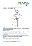
User manual
BIO-CK P Unit 25, 40, 60, 100 kW
With ‘NON-STUCK’ function
Contents
Product Description general
.....................................................................................................................................
Precautions
.....................................................................................................................................
Alternative connections of the boiler / burner
......................................................................................................................................
Start-up and Shutdown of the burner
......................................................................................................................................
Checking and adjusting combustion
......................................................................................................................................
Servicing and cleaning of the burner
......................................................................................................................................
Servicing and cleaning of the burner
......................................................................................................................................
Alerts
......................................................................................................................................
Optional equipment
......................................................................................................................................
Technical data
......................................................................................................................................
Electrical connection
......................................................................................................................................
Parts List
......................................................................................................................................
Notes
......................................................................................................................................
Product Description Overview:
The BIO-CK P Unit woodchip burner is a fully functioning burner with ignition and
extinguishing operation, in which a flame sensor monitors the combustion
process. The woodchip burner is equipped with an integrated auger, controller and
control unit with a digital display that can be programmed for different operating
options, allowing control of the sensors, woodchips, humidity and more. Adaptations
can be made to take into account varying sizes of fuel storage and supply options.
Woodchip burner is available in power ratings of 25 kW, 40 kW, 60 kW and 100 kW.
The burner can be connected to different boiler types by adjusting the adapter
between the boiler and burner.
Burner:
The outer casing of the burner is made enamelled steel. The combustion chamber
consists of interchangeable refractory ceramics. The grates and plates inside the
burner are made of acid resistant, fire resistant materials. The air fan speed is
regulated from the control system and connected to the junction box along with
sensors for controlling and monitoring all operations.
Ash Removal is carried out manually through the pull-out ash door.
There are input adjust screws and a flame sensor is mounted within the fall shaft.
This controls when the feed screw must start and stop, by detecting the brightness of
the flame. The auger is equipped with a sensor for indicating the temperature of the
screw tube. If the temperature becomes too high, the burner is stopped to avoid any
risk of overheating. Additionally if a temperature rise is continuously recorded within
the screw tube, this then triggers a water sprinkler system, which will then fill the
screw bottom with water.
Safety
Safety information is based on a risk assessment carried out under the provisions of
relevant EU Directives in order to meet the necessary European standards for CE
marking.
Installation, operation, maintenance and other procedures must be performed only by
trained personnel and in accordance with current standards. The boiler room where
the wood burning equipment is to be installed must also meet the requirements of the
latest edition of the National Board of Housing, Fire Protection section or within the
country of installations’ current regulatory framework.
Thermal protection of the boiler
Thermal protection of the boiler can be connected in two ways.
Connect the water supply is permitted if allowed constantly water supply on pressure
of 2,5 bar (see scheme 1).
If not enabled the constant water supply and pressure of min. 2.5 bar then is
necessary to install water tank and connect thermal protection on him (see scheme
2).
Water tank must be set at a minimum height of one meter from the pipe connection
on the conveyor (see scheme 2).
Water tank must be a minimum capacity of 30 liters, filled with water and have a hole
for air on top (see scheme 2).
Connecting to the conveyor must be made of non-combustible pipe from point 3 to
point 4!
Scheme 1.
Scheme 2.
Detail A:
LEGEND:
1
2
3
4
5
6
7
8
- Wood chip burner
- Wood chip transporter
- Connection - for connection with thermal safety valve
- Thermal safety valve as Caleffi 543 513
- Sensor of the thermal safety valve
- Connection - inlet to the thermal safety valve
- Connection - outlet from the thermal safety valve
- Water tank
NOTE: Use a mask when handling the woodchips.
WARNING! Electrical installation must be performed by a qualified
electrician.
Alternative connections of the boiler / burner
Boiler with normal operating thermostat, furnace with temperature sensors and
accumulator tank management.
There are three ways to control the burner, firstly by using a regular oil burner type
thermostat recorder to start and stop, to achieve a difference of about 3-6
degrees. Secondly, if you use a temperature sensor instead of a typical oil burner
type thermostat, the installer can then achieve a greater difference with operation
and get fewer starts and stops.
The third option is controlling the combustion by using the accumulator tank, which is
an advantage if there is an accumulator tank installed at the same time as the
burner. When you mount a sensor in the top of the accumulator tank and a sensor in
the bottom of the tank to control the burner, the tank then begins to cool and the
burner then stops when the bottom of the tank is hot. The combustion time is then
adjustable and can be adjusted according to the customers’ requirements. By
managing the combustion using an accumulator tank there is also a sensor mounted
to detect the temperature within the boiler to control any Laddomat pump.
Information on the wiring is on page 25.
NOTE: The burner should not be used without approved thermal
protection.
The display will show if an option is turned on. If it is just the thermostat, a boiler
symbol then shows whether it is On or Off, depending entirely on whether it is on or
off. If using just the boiler sensor it will instead appear within the boiler symbol the
current boiler temperature. If using the tank management setting, it will allow the user
to monitor and control the temperature at the top and bottom of the tank and get a
good overview of the temperature output.
See Figure 2.1
1
2
3
Figure 2.1.
Explanation.
1) Boiler Symbol showing information about the current boiler temperature.
2) Symbol for Laddomat pump.
3) Storage tank with a temperature display listing the temperature in the top and
bottom of the tank.
Control System
The woodchip burner is equipped with a control unit located in a separate control
cabinet made of painted sheet metal, and a control panel with display for setting the
operating parameters, service, maintenance and alarm systems. The control panel is
connected to the controller via the network and at the appropriate positions within the
boiler room.
The control system has been designed around the connection of wood chip storage
systems and conveyors. If any other equipment is connected which has not been
delivered by Centrometal, you must contact the dealer first. No warranty applies
unless the consent has been given by the dealer.
Site control panel with display, keypad and connectors.
Connections within the base.
1) USB input
2) Connections to the control cabinet
1) Display
2) OK button to confirm selections and choices
3) Arrow Up and Down, increase the value and move around within menus.
4) Arrow Left and Right, move between rows.
5) ESC key, exit the menus.
6) Red alarm lamp
7) Green OK light
8) Green operation lamp
Overview controllers
We always try to remain at the forefront of developing new features, making using
their systems both easy and understandable.
Within the display mode, you can follow what happens in the process when the
burner is running, where the display panel shows an animation of the system in
operation, such as the animation of a flame when the burner is running.
A major benefit of the control system is that it comes with a feature called ‘Nonstuck’, which means that if a piece of wood chip is blocked within the auger, the
motor reverses automatically to block the release.
The steering system has also been designed with a tank steering system, ie. that the
user can have the advantage of driving the burner against the accumulator tank to
increase the efficiency. If required, you would then need to buy the optional sensor
kit within the top and bottom of the accumulator tank which can be ordered through
the retailers.
Overview display of operating mode
Screen saver.
To save the screen you will find that it has a feature called screen saver in order to
extend the life of the display. After 5 minutes, it will enter this mode. To return, just
press a button to get back to where you were before.
Operation status, information
Below is the display mode to report on what the different symbols mean. The
operating mode contains much information about how the burner is set and what
happens in real time during the combustion process.
On page 10 this explains how a start-up works and how it looks on the display.
1) Boiler Symbol: Depending on what kind of operation has been shown either
the boiler temperature shows ON / OFF.
2) Symbol for Laddomatpump: If tank control is selected, the symbol displays an
animation when the pump is switched on.
3) Symbol for storage tanks and tank control selected, the current tank
temperature is displayed.
4) Process step: burning phase is divided into four stages, S1, S2, S3 and S4
and the current status appears here.
5) Time: the current process time of its operation.
6) Time: how long the process will be in operation
7) Stock: Symbol for hydraulic wood chip stocks. When the hydraulic pump is in
operation this symobol flashes the content level.
8) Fan Symbol: The symbol indicates an animation when the fan is in operation,
with the fan speed displayed above.
9) Flame symbol: This will show what level is the flame of the burner. If the level
is above the setting, it displays an animation of a major blaze. A reduced light
indicates the burner has reduced the flame. If there is a very small flame, an
animation appears indicating smoke.
10) Primer: When booting up, the drive symbol will flash and when the heating
process begins this then disables the ignition element and the symbol stops
flashing.
11) Temperature: overheating protection burner. Breaking strength 50 degrees.
12) Symbol for the burner: Normally, it must be set to 100%. Animation shows
when the screw is in operation.
13) Symbol for auger feed from the store: Current percentage value is displayed
and if the screw is in operation the animation indicates.
14) Clock: Displaying the current time.
Start Up
The following describes what happens when the burner is started. When the
burner should start depends on which way the steering is set and the three
options are: standard boiler thermostat, pangivare with differentiated on / off
switching and accumulator tank steering.
• OFF. It displays off in the corner, and the burner is avknäppt. Service
Location.
• While the burner is in standby mode SO-1 appears in the top right
corner. When the required temperature of the burner has been set this then
starts the auger and ignition. The animations for the auger feed and the
ignition then become active.
• In the upper right corner shows S-1 and means START 1 which is showing
the quantity of start-up fuel to be fed. Periodically check that the amount is
correct, see the settings. The time shows the time elapsed and the time of
combustion remaining.
• When the time is reached during the S-1 it goes over to the S-2, indicating
START-2 and only now is the igniter connected. The symbol of the ignition
element then flashes. The time is set from the factory but the installer can
adjust the time. When the time of the START-2 is over it goes over to the
next phase which is S-3 and then the fan starts. The fan mode is set to the
S-3 position to go with a higher speed and ensure that the start up is
faster.
• If the flame sensor detects the light within the flame has reached the set
value, the process then goes into S-4 which is the normal firing process. If
the flame sensor does not record light in the S-3 stage or the light
disappears for a long time (Factory set at 200 seconds) within the S-4
stage a new start-up attempt will be made. If unsuccessful, it will stop the
burner and an alarm will be displayed.
• When the burner stops it will display S-5.
• If the flame sensor registers the light in any of the start-up steps, it will
automatically switch to S-4 mode.
Description List:
OFF burner off
SO-1 Sleep Mode
S-1 Start 1, starting dose
S-2 Start 2, Only igniter
S-3 Start 3, Fan only
S-4 Normal operating mode.
S-5 Fuelling down phase
Memory functions
Within BIO-CK P Unit control is a useful feature that allows you to store
specific settings in the programme. It can be useful if you change woodchip
quality often or that you want to select different operating modes.
Within the Extras menu, you can scroll to SAVE and LOAD functions. Within
the save menu, there are five different memories that can be stored separately
from each other.
At the back of this manual, it is possible to write in what MEMORY 1-5
contains and it may be helpful to write down what you have saved in each
MEMORY.
To save you doing this.
When you have an operational setting that you want to save, browse your way
through to the OPTION menu and then press OK. You will then enter a menu
of different symbols, maneuver to the right or left arrow until you reach the
SAVE icon and press OK. Now you can see the five different memories and
choose one that is free, and press OK. You will get a dialog box if you want to
save. Press the up arrow until you come to YES and confirm by pressing
OK. You have now saved the current setting. Remember that if you save to a
memory where there is already data on you will overwrite the old.
To load a saved setting.
When you want to use a setting that you saved earlier, or go to the setting that
the installer did you do the following.
Go to Options and press OK, look for the LOAD function and press OK.
Browse now through the memory that you want to download and press OK. A
dialog box appears if you want to download or not, maneuver so that you get
the YES and confirm with OK. Now, this option is enabled.
Startup and Shutdown of the burner
Within normal mode / process, the burner display symbols are as shown in
Figure 1.1. By pressing the OK button, a symbol then says START / STOP.
Select the up or down arrow on the keypad to set the switch to 1 or 0 mode,
press OK button.Figure 1.2
When the switch is moved to position 1 it then starts a time countdown in the
upper right corner, it will then count for 15 seconds before the burner can
start. When 15 seconds have elapsed, it then starts the auger to enter the
starting dose and the bottom right of the display shows an animation of two
conveyors that move, while a symbol of the ignition element flashes. The time
for the loading dose is shown in the upper right corner (S1) and the time that is
set can be changed if necessary. The transporter nearest to the fan is the
auger that goes to the burner and the normal view is 100%.
Controling the amount of wood chips in the starting dose is done by opening
the door on the burner. The appropriate amount is approximately half the
height of the piercings on the ignition plate. If the first start up attempt fails, a
second start attempt then begins. NOTE: Do not forget to close the locked
door on the burner.
The shutdown of the burner is done in the opposite way to the above and as
soon as you have set the switch in position 0 this then stops the auger so that
the remaining chips can be burnt away.
Remember that when you should clean the burner the main switch should
always be set to 0 even if the burner is not running, and if the burner has been
running wait a while so that the hot parts cool.
Filling of screw conveyors
At some point it will surely happen that the wood chip storage has become
empty and that the augers have become empty, so that they then have to be
filled with wood chips before starting attempts. At the bottom of the menu
within OPERATING SETTINGS, there is a feature called
FILLING SCREW. Activating this then starts the augers that will switch on for
the time programmed by the installer to fill the augers with wood chips. This
function is only active when the burner is set to 0. Pressing the OK button then
starts the screws, which in turn then starts the hydraulic pump and runs
according to their timing.
If it continues to receive woodchips into the burner after the time runs out, you
can override this by pressing the ESC key and this then stops the process.
If there is not enough time to put wood chips into the burner then the process
is repeated again. NOTE: When using this function, you must monitor the
entire process and constantly keep a check that the burner is not overfilled.
This is how it looks on the display during the auger feed.
Menus and Sub menus
There are many useful features within BIO-CK P Unit control system, which
can be entered through the process mode by pressing the ESC key. Once in
the menu mode you can scroll through the menus by pressing the Left or Right
Arrow key, and confirming with the OK button to enter the menu. To exit the
menu, press the ESC key. When repeatedly pressing the ESC key then
returns you then to the process mode.
List of menus.
1) OPERATING SETTINGS: Here are the most frequently used functions such
as starting dose and flame sensor.
2) TEMPERATURE SETTINGS: Here are the settings if you use the boiler or
accumulator tank sensor control.
3) TEST LOCATION: Here you can manually run functions to ensure that
everything works as it should. One can operate the screw conveyors, hydraulic
pump and laddomat pump.
4) INSTALLATION: This menu is only for the installer. The menu is protected
by code. The major changes can then be made such as replacement of
engines or other major changes which you may need to contact professional
personnel for help.
5) EXTRA: This menu contains functions, for example to store a special
setting that you have made for a special type of operation to be later reused. There are also settings for date and time, backlight and contrast of the
display. There are also settings for frost protection and scheduled operation of
the burner. The alarm list is also available here.
Test Mode
Within the menus is a test mode. The test mode is used to manually test
most features to ensure that everything works as it should, for example
during installation.
Pressing the OK button when you are at the icon for the test mode you will
then get into a submenu, and there you have the features that you can try
manually.
The features available are:
Auger
Burner
Ash screw
Chimney Fans
Hydraulic Pump
Laddomatpump
Fan
Primer
If you press OK when you for are example within the auger menu, a new
picture emerges. Within the right side of the box, you can see the description
of what function you have selected and you also see a left arrow and right
arrow on the motors that can control the reverse gear. A judgement
can then be made as whether to run the augers in the right direction or if you
want to reverse the auger feed. Pressing the OK button will start the auger up
and will go as long as the button is held down, releasing it will then stop the
screw.
In the left panel of the display is a box with information about the three
different phases regarding the motors and required amperage they require in
real time and these are listed as I1, I2 and I3. At the bottom of the box it says
ASY, where you can see the asymmetry of the three windings of the motor.
When testing the other functions it also works in the same way, whereby
holding the OK button pressed then starts the feature.
Operating settings
Upon installation, the installer is able to set the all important values, such as
the boiler temperature and the feeding rate of woodchips to the burner. But
with a change of chip quality, you will need to fine tune the system to obtain an
optimal functioning of both the burners and woodchip stores.
The menu operation position is the most common setting to ensure proper
function. The Operation position is No.1 within the menu.
To go to the menu, press the ESC button and select Operation settings with
the Right or Left arrow and go into the menu with the OK button.
Within the drop-down list, there are parameters to change values or turn on or
off functions.
See figure 3.1
Once you are inside this section, there is a dropdown menu that you move the
cursor up or down arrow and you go into the menu by pressing the OK button
to exit the menu, or press the ESC key.
1) Choice of operation: Allows you to set how you want the burner to be
controlled, either by thermostat, boiler temp sensor or accumulator tank
control.
2) Starting dose: This is the amount of woodchips to be inputted during startup, and to adjust the time that the augers work in seconds. To ensure the right
amount of initial dose is correct, the S1 time must pass and be ready, which
then starts the burner and the auger motor and checks that the woodchips fill
at least half of the combustion zone, and can be increased or decreased as
necessary.
3) After the selected fan: This allows you to control the time that the fan will
operate after the flame has disappeared within the burner. Normally, it shall be
adjusted so that all the flames and embers have burned out when the time is
up.
4) Modulating: This function is for future use.
5) Fan and auger: This setting allows control of the auger conveyor drive and
speed regulation of the fan. These can be changed when you change the
woodchip quality. When and if you change the fuel feed auger this then
determines how much fuel the burner must have. The value of feed is given in
% and is factory set at 50%. Do not change the burner, as it should normally
be set at 100%.
NOTE: There are various fan types of 25kW and 40kW compared to 60kW
and 100kW and you must adjust the values depending on the size of fuel. For
25kW and 40kW, the minimum speed is 1200 RPM and the 60kW and 100kW
the minimum speed is 900 RPM.
6) Error list: If something is found wrong that then causes a stopping of the
system, it is then stored within this list. The last 50 error messages are stored
within the memory under date and time. All alarms have a code and the codes
can be found within the section under ERRORS AND TROUBLESHOOTING.
7) The fans: This function can be used if you have an exhaust fan installed.
Normally the system is working under pressure via the chimney, or if you let
the boiler run for very long times then the pressure is removed, and you may
then want to install an exhaust fan.
It can happen if you keep firing against a large storage tank when the burner is
on standby for several days (and/or over the summer), that it can be hard to
get adequate pressure within the chimney. This phenomenon can also occur
when solar panels are being used within the system. To see the current status
of the chimney you can see it within the operation mode, which when pressing
the right button then allows a symbol of the chimney with a fan to come up. By
pressing the left button it is then concealed.
8) Flame sensor: It is the flame sensor that allows the GOTFire ™ burner to
achieve a fast and smooth startup and heating function. The flame sensor is
active throughout the burning process and it takes care of the augers should
they not operate or decide whether the ignition element is activated or not. The
value of the intensity of the flame sensor function is an Ohm value and is
factory set to 140 ohms. Sometimes it is necessary that you adjust this value if
using more damp woodchips. NOTE: You may not set the value higher than
160 Ohms.
9) Opening stores cap: This is very useful in those cases where the
woodchip store has a hydraulic opening filler door. When the door is opened
you can then go into the feature opening the hydraulic storage and when
you're there start one time circuit for 5 minutes, which makes it possible by
using the start button to run the hydraulic pump so that you can open the
lid. The burner must be set to OFF in order to access this feature. In the
operation of all store's door, you must have full visual control over the store so
no pinching can be done. When you then press the button to start the pump,
you have 5 minutes to open or close. When five minutes is over, you can not
start the pump with the start button then you need to activate the time the
circuit again. This function is very good when the user can not open the door if
you do not have the key out of the store.
10) Burner self-cleaning: This function is for future use.
11) Filling augers: At some point your storage may run out of fuel and the
augers are empty. This will then sound an alarm that it can not start and this
is when this feature is useful. At first boot, the installer can set the time to fill
woodchip from the augers. When you go into this feature within the display of
a symbol of a store and two transporters, you can then start the feature.
Press the OK button and start the augers.
NOTE: When using this feature, you must not leave the equipment
unattended. It can be only that there has been a gap in the wood chips in the
auger and the woodchip flow can be faster than expected. To stop filling you
press the ESC key.
Checking and adjusting combustion
Through inspection door on the burner you can see the operation of supply of
woodchips and if the amount of air for combustion is set correctly.
NOTE: Do not forget to close the locked door. The burner should burn for at
least 10 minutes before checking and the adjustment of any settings made.
A smooth, even burning woodchip layer that does not tend to increase or
decrease in thickness is the ideal. If for example the grate area starts to show
out of the burning wood chips then the fuel supply must be increased slightly.
The amount of fuel supply is able to be adjusted within the auger operation
settings submenu AUGER AND FAN. When changing the% value it is
advisable to wait at least 10 minutes before each change of value so that the
first amendment has had time to take full effect.
Alternatively, you can change the air volume. This is done by changing the air
fan speed.
A good flame burns slowly with little yellow-orange colour and flickering flame
effect.
Birch wood burns with a more bluish, smaller flame. This then affects the
settings of the light sensor.
The flue gas temperature depends on several factors. The most important is
the boiler design.
This includes above-and below combustion, the number of convection tubes,
whether there is horizontal or vertical convection and the boiler
output. Recently de-sooted boilers result in lower flue gas temperatures.
The problem with the high temperatures of flue gases can cause the following
actions:
• Reduction in the draft. NOTE: at least 1mm VP is required for the light
sensor test.
• Reduces the burners input of woodchips.
• By installing some type of convection plate within the furnace so that the flue
gas can go further way.
• Increase soot within the boiler.
Adopting measures to reduce the flue gas temperature can then increase the
efficiency.
Servicing and cleaning of the burner
After installation, you should then carry out a routine operational check and
clean the burner grates to control the amount of ash generated. This is to get
an idea of how often the burner needs to be cleaned and how often the ash
should be removed.
Ash removal is done as needed, depending on woodchip quality. Be aware of
variations in woodchip quality and moisture content, which affects the ash
quantity and combustion.
To clean the burner, it is also advisable to remove the flame sensor and see if
it needs cleaning. There is a coating on the transparent part of the flame
sensor which should be cleaned with a glass cleaner. See Figure
4.1. NOTE: Do not use solvents or flammable substances for cleaning. The
burner can not be started without the flame sensor in place and you must not
remove the flame guard during operation.
A clean furnace increases efficiency, resulting in lesser woodchip
consumption. In addition, ash removal is best done whilst reviewing the
woodchip burner and the attached equipment.
Check that there is sufficient drag into the burners’ drag test hole.
There must be at least 1.5 mm VP pressure during operation.
For more detailed service and maintenance work this should only be
performed by specially trained personnel.
Warning! Risk of burns. Wear gloves.
Servicing and cleaning of the burner
• NOTE! The ash removal of the burner must be turned off via the hand unit.
• If the burner has just been running, wait until the burner is stopped and
cooled.
• Open the locking device of the ashtray and pull it out of the burner. Place the
ashtray on a non-combustible, level surface. NOTE: use gloves.
• Remove grate from the ash pan by lifting straight up. Brush off excess ash
from the grate above and check that the vents are open. If there are clogged
vents these should be cleaned with appropriate tools.
• Remove ashes from the ash pan and replace the grate in the ash pan.
• Make sure the guide pins on the grate are in the right position on the ash pan
mounts.
• Before the ash pan is put back into the burner, remove any ash in the ash
drawer space within the bottom of the burner. Replace the ash pan in the
burner and close the locking devices of the ashtray.
• Upon completion of ash removal, the operating mode must be set within the
display unit.
• Ensure that all equipment is cleaned and that no combustible items are
related in or around the boiler room.
• Clean also the fall shaft which is mounted on top of the burner. After a while,
dust can get coated there. NOTE: The burner must be turned off and no fire or
glow may be in the burner, to avoid the the risk of dust explosion.
• Start the burner
Warning! Risk of burns.
NOTE: The ashes may still contain burning glues and so must be collected
and stored in non-combustible containers and with a lid.
NOTE: Always wear gloves as the ash pan and grate can be hot.
ALARM MESSAGES:
The alarm will present within a window of the display with an error code and a
brief message about why the alarm has been made. By pressing the OK
button, a message is then displayed explaining what the alarm is for and what
to do. The Alarm list within the menu operation position.
The system stores 50 alarms within the alarm list so that you can easily
provide an overview of the alarms that have occurred. The alarms are stored
with date and time. See Figure 5.1
If there has been an alarm which has resulted in the burner stopping you then
have to go to the operating mode and start the burner again.
Below is an explanation of the alarm texts:
E-2001: Faulty boiler sensor. Troubleshoot and replace if necessary
E-02: Tank top sensor error. Troubleshoot and replace if necessary
E-03: Tank bottom sensor error. Troubleshoot and replace if necessary
E-04: Flame sensor error. Troubleshoot and replace if necessary
E-05: Burner door open door. Close and restart
E-06: Cover screw stores open. Close lid and restart
E-07: Door open to storage. Close lid and restart
E-2008: Faulty fan. Debug fan and replace if necessary
E-09: Communication error. Check the cables between the burner and control
cabinet
E-10: Auger motor blocked. Some of the auger motors are blocked.
E-11: Auger motor blocked. Some of the auger motors are blocked.
E-12: Error on startup. Check the flame sensor and igniter
E-13: Error mode. Check if there are woodchips within the container
E-14: Module fault. Check for electrical faults in power cables
E-15: Flue gas exhaust temp too high, clean the boiler
E-16: Auger temperature. Too high temperature within the auger. Clean the
boiler
E-17: Flue gas sensor error. Check sensor and replace if necessary
E-18: Burner sensor error. Check sensor and replace if necessary
E-19: Module fault. Check electrical connections in electrical system
E-20: Module fault. Check electrical connections in electrical system
E-21: Module fault. Check electrical connections in electrical system
E-22: Module fault. Check electrical connections in electrical system
Troubleshooting Chart
Indication
Burner not working
Alarm: E-1
Cause
Overheating within the boiler
Action
Reset the inbuilt overheating protection thermostat. Troubleshoot and find
fault.
Indication
Burner not working
Alarm: E-16
Cause
Triggered overheating protection within the auger tube
Action
Clean boiler and flues. See there is sufficient drag into the boiler. Reset
overheating protection within the control panel.
Indication
Fan and ignition starts but not the auger
Alarm: E-05
Cause
Door switch sensor not recognised
Action
Check to see if it is full of wood chips in the burner, or using a long stick
lift the door slightly. Adjust if necessary. Change the switch.
Indication
The burner starts, and then goes out.
Alarm: E-12
Cause
Coating on Flame sensor.
Action
Remove the flame sensor and clean. Note: Flame sensor may not be cleaned
with solvents.
Indication
Burner will not start
Alarm: E-14
Cause
Motor function is not activated
Action
Reset motor protection. adjustment of engine protection may be required if the
restart fails. Performed by the installer.
Indication
Woodchip auger will not start
Alarm: E-06
Cause
Door Switch not operational
Action
Close cover. Check the sensor on the door. Check to see if it is full of wood
chips in shaft, or using a long stick lift the cover.
Indication
Burner will not start
Alarm: E-09
Cause
Faulty contact
Action
Check connection cables on the display. Burner steering system
For other errors contact professional for help.
Optional Equipment
1) Increased fall shaft which separates the burner from the supply screw.
2) Door Switch for woodchip storage filler door, able to stop the entire plant
after 5 min.
3) Lambda control (λ) for the monitoring of flue gases from the boiler. See
separate description.
4) Woodchip Storage in sizes of 4.5 m³, 9m ³ and 13m ³. Even less can be
obtained.
5) Flue gas.
6) GSM alarm.
7) Hydraulic oil level reader.
Contact your local dealer for more information about each of the optional
parts.
Technical data
Model: BIO-CK P Unit 25, 40, 60, 100 kW burner with auger.
Fuel type: Wood chips
Woodchip size: 50 mm strip length direction
Moisture content: 30% max.
Electrical connection 220V/10A
Output Power: 50W. Start: 1kW. Storage room with a connecting auger.
Noise: Under recommended maximum values.
Recommended under pressure: 1.5 mm-VP (15Pa) within the burner during
operation.
Weight in Kg:
Dimensions in mm:
Electrical Specifications: Standard
Voltage fan: 220V 1 Phase
Power screw: 220V 3 phase
Fuse: 10A
Electrical connection
CONNECTION DIAGRAM.
NOTE: The syetem may not start before the heat protection system for the
boiler is connected properly. The connection is labelled Safety thermostat.
All installation shall be done by a qualified electrician.
All electrical installations made from the large control cabinet are to be
mounted on the wall with four screws. Make sure the controller is protected
from external influences and that it is protected from water and dust.
Full installation of the burner is fitted with two pieces: the connectors are to be
connected on the low side of the controller. There are various sizes of
connectors and if not mounted correctly can cause an error. Make sure they
are fully engaged.
Cables from the burner to the controller have a standard length of 6 metres, if
you need longer, there is an extension rate of 2 metres which can be
purchased. Please contact the reseller.
The terminals featured are described on a sticker at the bottom of the
terminals, and the explanation is described below.
On the left of the decal is the POWER SUPPLY and the incoming voltage is
380-400 volts. This is three phase with a minimum of 10 amps with ZERO
management.
NOTE: If the facility shall be installed in Norway then other connection options
might be required as it is usually 220 volts and three phase, but ZERO
management. Then, a Phase L2 should be drawn to ZERO
terminals. Although all the three phase motors are to be switched to the 220
volt option.
SAFETY THERMOSTAT: This is the thermal protection to the boiler and
should be installed prior to commissioning.
FUEL STORAGE TANK TRANSPORT: This motor is connected from the
woodchip supply. Maximum motor size is 1 kW.
BURNER CARRIAGE: Here is connected the auger which is mounted onto the
burner. Maximum motor size of 1 kW
TANK MIXER: Connect the hydraulic pump station in those cases where it is
used. Max 1.1 kW
ASH CLEANING: Function for future use.
Accumulation TANK PUMP: For those cases where the tank is in the system
and a Laddomatpump connected.
FLUE GAS FAN: If the chimney fan is used. The fan starts when the burner
starts.
D1: Here the boiler thermostat setting is connected for such use.
D4: This is the connected door switch on the storage auger.
D5: This door switch is connected to the storage roof.
D6: Connect button to operate the hydraulic pump for the hydraulic opening of
the storage lid.
A1: For the connection sender within the boiler, if the connection sender must
be mounted in the casing tubes within the boiler.
A2: Sensors for fuel stops within the accumulator system, connected in the
casing tubes around the sensor.
A3: Sensors for the tank bottom within the accumulator system, connected in
the casing tubes around the sensor.
A4: Sensor display of flue gas.
A6: Sensors for outside temperature.
WARRANTIES
Normally Centrometal provide a 2 year warranty on all of its products. Any
modification of the equipment is prohibited without written.
If customers want to combine our system with other systems such as for
example by using another woodchip storage solution, this then invalidates the
Centrometal guarantee of functionality on which our products are designed to
work together. Problems can occur if other products are combined with
Centrometal products.
Centrometal also have a requirement that all electrical installation work on
their systems must be performed by certified electricians responsible for such
connections. If the installation has been carried out by someone without
permission it will also negate any of the Centrometal warranty.
Confirmation of the electrician may also be required by Centrometal.
If the equipment has been installed without a qualified electrician, it may then
require a Centrometal representative to restart the system without a licensed
electricians’ consent.
We also have an obligation to those who install our products who have
undergone training for our products. If you have not taken a course, you
should come to Centrometal for education.
Parts List
Number Designation
1) Primer
2) Flame sensor
3) Grate
4) Intermediate Ceramics
5) Fan
For spare parts please contact your nearest dealer.
Please quote the burner size when in contact with dealers.
Woodchip Quality
The benefits of choosing woodchip as a fuel is that you can capitalise the most
from the use of woodlands or forests, even more than which can be used for
firewood or pellets. Woodchips are cheap to produce and are often locally
produced. What is needed is a building for storage of the woodchips and
typically a tractor with a loader for the loading of woodchip supply. If you are
unable to buy ready-chipped wood, one option is to chip yourself with a so
called “chipper”. There are many forest owners and farmers working with the
supply of woodchips, so it pays to search your local area for someone who
sells finished woodchips.
For the best heat value, the chips must be dry. Ideally, the moisture content
does not exceed 30%. If the moisture content is too high you can get problems
with the burner does which does not give the optimum effect which it has been
designed to achieve. If woodchip stocks are stored outdoors, you can have
problems with freezing of the wood chips if there is too high moisture
content. A dry woodchip allows for a faster start up and that means greater
efficiency.
Much of the material within the wood or forest can advantageously be used,
but it is preferable not to include leaves, sand and pine needles. Centrometal
guarantee the equipment for 50 mm maximum size of the woodchips in the
wood fibre direction. Larger fractions may malfunction.
It is not recommended to use woodchips from the thinner branches and leaves
as the combustion produces much more ash within the combustion chamber
of the burner.
We usually recommend that you harvest in the winter and let the woodchips
naturally dry during the spring and summer to be then chipped in early
autumn. If you want to be really careful or if the wood should be stored for a
long time, you should add a rain cover over. If you handle the chipping
yourself, only material under this recommendation is recommended to bring
the moisture content to around 20-30%. The lower the moisture content the
better the heat value containing the chips, which means that the consumption
of woodchips can be kept down.
There is no disadvantage to prepare the woodchip a year before so that it has
a good chance to dry for a long time.
NOTES…………….