1
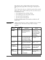
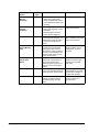
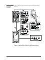
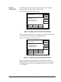
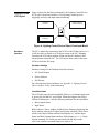
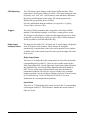
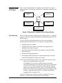
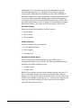
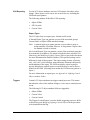
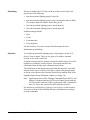
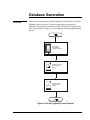
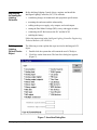
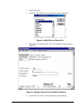
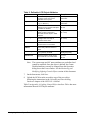
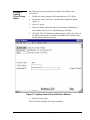
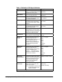
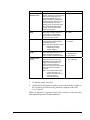
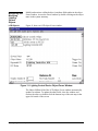
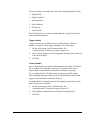
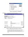
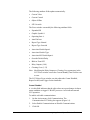
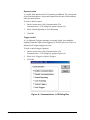
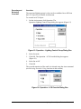
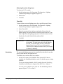
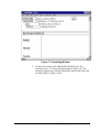
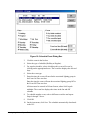
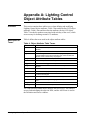
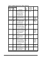
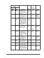
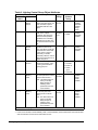
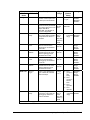
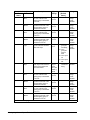
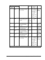
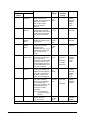
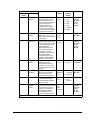
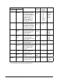
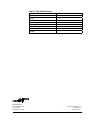
Technical Bulletin Issue Date 11/01/01 Lighting Control Objects Introduction Page 2 • Overview 2 • Description 2 • Application 2 • Capabilities 3 • Functional Overview 5 • Operator Interface 6 Engineering 8 • Overview 8 • NCM Capabilities and Limitations 8 • Operation of an LCD Object 9 • Operation of an LCG Object 11 Database Generation 15 • Overview 15 • Engineering the Intelligent Lighting Controller 16 • Defining a Lighting Control Device Object 16 • Defining a Lighting Control Group Object 19 • Monitoring and Modifying Lighting Control Objects 22 Appendix A: Lighting Control Object Attribute Tables 31 • Overview 32 • Description of Terms 32 © 2001 Johnson Controls, Inc. Code No. LIT-636105 1 www.johnsoncontrols.com Introduction Overview This document describes the online configuration of Lighting Control Device (LCD) and Lighting Control Group (LCG) objects using an Operator Workstation (OWS). Before defining these objects, review the Intelligent Lighting Controller’s (ILC) capabilities and theory of operation as described in the Intelligent Lighting Controller Engineering Technical Bulletin (LIT-6385010). Description The ILC consists of two object types, the Lighting Control Device object and the Lighting Control Group object. Defining these objects integrates lighting control functions with the Metasys Building Automation System (BAS). The LCD object is the hardware object manager. The LCD object defines the hardware interface between the Network Control Module (NCM) and the ILC, and tracks the status of the ILC’s switches and relay outputs. Each controller uses one LCD object. The LCD object is the only object that communicates directly with the ILC via the N2 Bus, and only one LCD object can be defined for each ILC. An LCG object is the software representation of an ILC lighting group. One LCG object corresponds with one physical or logical lighting group residing in the ILC. Each LCG object is responsible for tracking the status of its corresponding lighting group and reporting status changes throughout the Metasys BAS as required. The LCG object also defines groups of relays for On/Off control. Up to 32 LCG objects can be mapped to each ILC. Application The purpose of LCD and LCG objects is to integrate lighting control functions with the Metasys BAS. Together these objects monitor the ILC, respond to status changes, and distribute this information to other devices on the Metasys network for further action. Lighting Control objects continuously monitor many functions of the Intelligent Lighting Controller. If any of these functions change state, the LCD and LCG objects can report those changes to Operator Workstations (OWSs). The functions reported include: 2 • current state of the lighting groups (On or Off) • online/offline • operator overrides initiated at the OWS Lighting Control Objects Technical Bulletin Some functions, such as a Change-Of-State (COS) in the associated lighting group object going offline, can also trigger a control process to run. The LCG object allows the user to schedule the operation of the associated lighting group. These schedules contain up to four events. Each event can be programmed four ways: • turn the lighting group On with blink at Off time • turn the lighting group On without blink at Off time • force the associated switch input On • force the associated switch input Off In addition, the lighting groups can be manually overridden On or Off from the OWS. Capabilities Lighting Control objects have a number of capabilities. Some are common to both object types, while others are unique. Table 1 lists object capabilities. Table 1: Object Capabilities Capability Object Type Description Purpose Hardware Interface LCD The Lighting Control Device object defines the physical connections between the ILC and the NCM. Provides a common communication link between the ILC and the Metasys network. COSs in the ILC are converted to digital data that can be understood by Metasys software. Change-of-State (COS) Reporting LCD, LCG A COS report may be sent to one or more operator devices when the object goes offline, if the current state of a lighting group changes, or if a lighting group is overridden at the OWS. Notifies multiple operators if, for example, the ILC goes offline. Control Process Triggering LCD, LCG Triggering means that various conditions, such as an object offline, cause a control process to run. Provides automatic system response to realtime events. Current Control and Current Value Monitoring LCG Current Control indicates the dominant feature turning the associated lighting group On or Off. Current Value indicates whether the associated lighting group is On or Off. Facilitates troubleshooting by showing both the current state of the associated lighting group and its controlling feature. Disable and Enable Communications LCD, LCG • Disable prevents the object from communicating with the ILC. Suppresses COS reporting and control process triggering when the ILC is being tested. • Enable resumes communications. Continued on next page . . . Lighting Control Objects Technical Bulletin 3 Capability (Cont.) Lock and Unlock Reports Command Object Type Description LCD, LCG • Lock Reports prevent the object from sending COS reports to OWSs and printers. Purpose Inhibits nuisance reports. • Unlock Reports resumes COS reporting. Lock and Unlock Triggers Command LCD, LCG • Lock Triggers prevents the object from triggering control processes. Inhibits nuisance triggering of control processes. • Unlock Triggers resumes control process triggering. 4 Auto Dial-out LCD, LCG Auto Dial-out indicates whether a remote Personal Computer (PC) or dial-up link should be called as soon as a critical report is issued. Notifies personnel of critical alarm conditions when local OWSs are unmanned. Previous and Current Monthly Total LCG Previous Monthly Total shows the total time the associated lighting group was On for the past month in hours and tenths of hours. Current Monthly Total shows the total amount of time for the present month. Allows the operator to track usage for billing, energy management, or other purposes. Relay Output/ Switch Input Status LCD Relay Output/Switch Input Status monitors the current status of each of the 40 relays and 32 switch inputs, and notes if a relay is not in its commanded position. Tracks status of relay outputs and switch inputs and warns of a possible faulty relay. Scheduling LCG Scheduling allows each lighting group to be programmed with up to four events for On/Off control. Saves energy by automatically turning lights On and Off according to a programmed schedule. Overrides LCG Overrides allow personnel to manually control the state of each lighting group from the OWS. Provides emergency lighting control from a central location. Lighting Control Objects Technical Bulletin Functional Overview Figure 1 shows how the LCD and LCG objects function in the Metasys network. Figure 1: Lighting Control Objects in the Metasys Network Lighting Control Objects Technical Bulletin 5 Operator Interface An operator may access a Lighting Control object through the OWS or Network Terminal. At the OWS, the LCD and LCG objects can be defined, modified, displayed, and commanded. At the Network Terminal, LCD objects can be displayed, and LCG objects can be displayed and commanded. OWS Lighting Control Device Object The following LCD object screens are available at the OWS: • the LCD object Definition window, for defining an object • the LCD object Focus window, for monitoring and modifying object attributes • the LCD object Action - Communication dialog box, for executing object commands such as Disable and Triggers Locked Lighting Control Group Object The following LCG object screens are available at the OWS: 6 • the LCG object Definition window, for defining an object • the LCG object Focus window, for monitoring and modifying the object attributes • the LCG object Action - Communication dialog box, for executing object commands such as Disable, Triggers Locked, and Reports Locked • the LCG object Action - Override dialog box, for overriding the associated On or Off or for turning the lighting group On for a specified amount of time • the LCG object Schedule Event dialog box, for programming the associated lighting group with up to four schedules Lighting Control Objects Technical Bulletin Network Terminal (NT) The LCD object screen at the NT is used to view and access feature information like the status of the 40 relay outputs. Figure 2 illustrates the LCD object screen. Select an available option, then press ENTER. LOG OFF HOME NC_4_HDW Building #1, 3rd floor east LTG_CLR4 ONLINE Lighting Controller 4th floor REFRESH PREVIOUS DISABLE HELP CLEAR Devscren Figure 2: Lighting Control Device Object Screen The LCG object screen at the NT is used to view feature information and to schedule and override the associated lighting group. Figure 3 illustrates the LCG object screen. Select an available option, then press ENTER. LOG OFF HOME 1ST FLOOR Admin. Bldg #C 1st floor LTG_GRP 2 ON Sched West side cafeteria REFRESH PREVIOUS HELP DISABLE OVERRIDE SCHEDULE HOLD AUTO Ntscreen Figure 3: Lighting Control Group Object Screen For more information on using the NT to schedule and override the lighting groups, refer to the Scheduling a Lighting Control Group and Overriding Lighting Control Groups chapters in the Network Terminal User’s Manual. Lighting Control Objects Technical Bulletin 7 Engineering Overview Lighting Control Device (LCD) and Lighting Control Group (LCG) objects each have separate responsibilities, yet they interrelate to provide a complete lighting system integrated with the Metasys system. See Figure 1 for an illustration of the operation and interaction of Lighting Control objects with each other in the context of the Metasys network. There is only one LCD object for each Intelligent Lighting Controller (ILC) on the network. The LCD object is the hardware object or communication link between the ILC and the NCM to which the ILC is connected. The LCD object polls the ILC via the N2 Bus and uses the information to monitor the status of the ILC and its relays and inputs, report COSs, and trigger controls processes. Up to 32 LCG objects can be defined for each ILC. These objects allow the selection of up to 40 relays for On/Off control by schedules or overrides. Although each LCG object receives information about the associated lighting group from the LCD object, it is responsible for group mapping and monitoring, reporting COSs, and triggering control processes as needed. Most of the interaction between the lighting groups in the ILC and the Metasys system is handled by LCG objects. NCM Capabilities and Limitations 8 The ILC uses a standard NCM. The hardware is limited to up to 50 ILCs on an N2 Bus without a repeater or up to 89 ILCs on an N2 Bus with a repeater. However, the NCM-100’s software has a capacity limit of approximately 350 objects, which only allows about 11 panels if all 32 lighting control groups are programmed in each panel. The NCM300 Series expanded memory allows the system to operate to the capacity of the hardware limitations. Refer to the Network Control Module 300 Series Technical Bulletin (LIT-6360251). Lighting Control Objects Technical Bulletin Operation of an LCD Object Figure 4 shows the functions performed by the Lighting Control Device (LCD) object: hardware interface, COS reporting, control process triggering, and relay and input status monitoring. Hardware Interface Relay and Input Status Monitoring Device Change-of-State Reporting Triggers Devmap Figure 4: Lighting Control Device Object Functional Model Hardware Interface The ILC is physically connected to the NCM via the N2 Bus; however, it is still necessary to define an LCD object to map to the ILC. Mapping associates the LCD object attribute fields with specific hardware and internal points within the ILC. The LCD object must reside in the same NCM to which the ILC maps. Hardware Settings Hardware settings for the Hardware Interface include: • NC Trunk Number • Device Address • Poll Priority For a description of these attributes, see Appendix A: Lighting Control Object Attribute Tables in this document. Unreliable States The LCD object may become unreliable if there is a communication break or power loss and the ILC goes offline. When this happens, the Object Offline field displays a Y and the following attributes become unreliable: • Relay Output Status • Input Status Both an object’s Focus window and the System Summary displaying the object indicate when an LCD object has become unreliable. In the Focus window, the Object Offline attribute field displays a Y, and the Input Status and Relay Output Status attribute fields change to ?????. In the System Summary, the Value text associated with the object reads OFFLINE, and the associated Status text reads OFF. Lighting Control Objects Technical Bulletin 9 COS Reporting The LCD object reports changes in the Object Offline attribute. These reports have a fixed report setting of Critical 4. The report setting (in order of priority: crit1, crit2, crit3, crit4, followup, status and none) determines the priority and destination of the report. All critical reports can be displayed in pop-up dialog boxes at OWSs. For more information about this attribute, see Appendix A: Lighting Control Object Attribute Tables. Triggers The only LCD object attribute that is triggerable is the Object Offline attribute. If this attribute changes, it can cause a control process to run. The Triggers Locked feature is used to disable triggering processes. Refer to Monitoring and Modifying Lighting Control Objects in this document for the procedure to lock and unlock this flag. Relay Output and Input Status The status of each of the ILC’s 40 relays and 32 switch inputs is displayed at the LCD object Focus window. These statuses do not update automatically; to update them, either close and reopen the Focus window, or double-click on the bottom step of the stair-step in the upper left corner of the screen. Relay Output Status This series of 40 fields shows the current status of each of the 40 possible corresponding relays on the ILC. There are four possible states for this field: Open (lights Off), Closed (lights On), Open/Alarm (lights Off when they should be On), and Closed/Alarm (lights On when they should be Off). The two Alarm states indicate that the relay does not match its commanded condition. This may be a sign of a faulty relay or another hardware problem. See the Intelligent Lighting Controller Commissioning and Troubleshooting Technical Bulletin (LIT-6385037) for more information on correcting hardware problems. Input Status This series of 32 fields displays the status of each of the 32 corresponding switch inputs on the ILC. The field shows whether the switch contact is Open or Closed. 10 Lighting Control Objects Technical Bulletin Operation of an LCG Object Figure 5 shows the functions of a Lighting Control Group (LCG) object: group mapping, COS reporting, control process triggering, scheduling, and overrides. Lighting Group Mapping Scheduling 6 GROUP Change-of-State Reporting Triggers LCGop Overrides Figure 5: Operation of Lighting Control Group Objects Group Mapping The LCG object represents a lighting group residing in the ILC. A lighting group is a collection of output relays that are assigned through software for On/Off control. Use the LCG object Definition window to create a new group that automatically downloads to the ILC. Creating a new group includes: • assigning the group a number • deciding which relay outputs are included (relay outputs may be included in more than one group) • specifying which of the included relay outputs are allowed to blink before going Off • defining switch input parameters • determining which switch inputs are interlocked with the associated switch input through the Cleaning Crew feature Notes: If more than one group shares a relay output, the relay stays On as long as any one group requests it to be On. Overlapping LCGs can cause confusion because more than one group controls the relays, and some relays may be on and some may be off. The LCGs have only one current value and, therefore, cannot convey the status of all the relays. To avoid this confusion, define LCGs with one relay per group instead of overlapping, using Multiple Command Objects (MCOs) or Graphic Programming Language (GPL) to control LCGs. Use the LCG object Focus window to monitor or modify LCG object attributes or to control the associated group of relay outputs. Lighting Control Objects Technical Bulletin 11 Although the LCG object does not physically communicate with the associated lighting group, it is responsible for the group’s mapping configuration, monitoring and controlling its status, and facilitating its interaction with the rest of the Metasys BAS. Communication between the LCG object and the associated lighting group is channeled through the LCD object to the NCM. In turn, the NCM determines any COS for that group and sends the data to the LCG object. All data displayed or printed about an LCG object comes from the NCM, not directly from the ILC. Hardware Settings Hardware settings for the hardware interface include: • System Name • Object Name • Group Number Software Settings Software settings for the group include: • Switch Input Parameters • Relay Outputs • Cleaning Crew Unreliable or Offline States An LCG object may become unreliable if it goes offline due to a communication break or power failure. The following attributes become unreliable if an offline condition occurs: • Current Control • Current Value Both the Focus window and the system summary indicate when an LCG object is unreliable. In the Focus window, the Object Offline attribute displays a Y in its text field and the text fields for the Current Control, and Current Value attribute is replaced with ???. In the System summary, the Value text associated with the LCG object reads OFFLINE, and the associated Status text reads OFF. 12 Lighting Control Objects Technical Bulletin COS Reporting Several LCG object attributes can issue COS reports when their values change. These reports can be sent to one or more devices, including the OWS and report printers. The following attribute fields affect COS reporting: • Object Offline • S/W Override • Current Value Report Types The LCG object has two report types: Normal and Override. A Normal Report Type can generate a report if the associated group’s Current Value or Object Offline attributes change. Note: A normal report type cannot generate a report when a group is being manually overridden; however, it can generate a report when the manual override is released. An Override Report Type can generate a report if the associated group has been manually overridden or if a manual override has been released. (See Monitoring and Modifying Lighting Control Objects later in this document for more information on manual overrides.) The specified settings can be different for each of these reports. The report setting (in order of priority: crit1, crit2, crit3, crit4, followup, status and none) determines the priority and destination of the report. The OWS can display critical reports in pop-up dialog boxes, and all reports except None may be sent to files or printers at the OWS. (Selecting None means the COS does not generate a report.) For more information on report types, see Appendix A: Lighting Control Object Attribute Tables. Triggers Certain LCG object attributes can trigger control processes. This means that when the value of the attribute changes, it can cause a control process to run. The following LCG object attribute fields are triggerable: • Object Offline • Current Value • Current Control The Triggers Locked feature is used to disable triggering processes. Refer to Monitoring and Modifying Lighting Control Objects for the procedure to lock and unlock this flag. Lighting Control Objects Technical Bulletin 13 Scheduling If desired, schedule the LCG object with up to four events. Each event may do one of the following: • turn the associated lighting group’s relays On • turn the associated lighting group’s relays On and allow them to blink five minutes, then two minutes, before they go Off • force the associated lighting group’s switch input On • force the associated lighting group’s switch input Off Schedule settings include: • Days • Event • Event start time • Event stop time See the Database Generation section of this document for more information on scheduling. Overrides To override the associated lighting group’s relay outputs, use the LCG object’s Focus window. There are two types of overrides: a manual override or one with a timed ON. A manual override turns the outputs associated with this object On or Off, regardless of schedules or other requests. The outputs remain in the commanded state until the Auto command releases them. Timed ON turns on the outputs associated with this object for a specified amount of time (up to 99 hours). If no time is entered, the group remains on for the value shown in the Override Default Delay attribute field of the Lighting Control Group Definition window (see Figure 10). Note: Applications such as GPL, Multiple Command Object (MCO), and Metasys Telephone Interface (MTI) have a higher priority than the LCGs Override command. If these applications send a command to the LCG object, they control the object until they release it. See Monitoring and Modifying Lighting Control Objects in the Database Generation section of this document for more information on executing override commands. 14 Lighting Control Objects Technical Bulletin Database Generation Overview This section describes how to define Lighting Control Device (LCD) and Lighting Control Group (LCG) objects using online generation. In addition, it explains how to monitor, modify, and control the objects from their Focus windows. Figure 6 is a flow diagram illustrating the definition process. Engineering the Intelligent Lighting Controller Device 6 Group Defining a Lighting Control Device Object Defining Lighting Control Group Objects Flow Figure 6: Defining Lighting Control Objects Lighting Control Objects Technical Bulletin 15 Engineering the Intelligent Lighting Controller Before defining Lighting Control objects, engineer and install the Intelligent Lighting Controller (ILC). This includes: • considering design, environmental, and equipment specifications • mounting the enclosure and the subassembly • cabling to the power supply, relay outputs, and switch inputs • setting the Dual Inline Package (DIP), rotary, and toggle switches • connecting the N2 Bus between the ILC and the NCM • enabling the battery Follow the instructions in the Intelligent Lighting Controller Engineering Technical Bulletin (LIT-6385010). Defining a Lighting Control Device Object The following section explains the steps involved in defining an LCD object. 1. Double-click the system that will contain the new LCD object. 2. Click New on the Item menu. The Item New dialog box appears (Figure 7). Figure 7: Item New Dialog Box 16 Lighting Control Objects Technical Bulletin 3. Click N2 devices. 4. Click OK. The Add N2 Device dialog box appears (Figure 8). Figure 8: Add N2 Device Dialog Box 5. Highlight LCD, and click OK. The LCD Definition window appears (Figure 9). Figure 9: Lighting Control Device Definition Window 6. Define the LCD. Table 2 lists the definable LCD attributes. Lighting Control Objects Technical Bulletin 17 Table 2: Definable LCD Object Attributes Attribute Description Entry Values . . . Object Name Identifies the object (e.g., LC_HWD). The object name must not be duplicated in the system. 1 to 8 alphanumeric characters Expanded ID Further identifies the object (e.g., LC Device 1). 0 to 24 alphanumeric characters Comm Disabled Specifies whether communication between the ILC and the LCD object is enabled or disabled. Y = Yes N = No Graphic Symbol # Displays the reference number of the graphic symbol composed to associate with this object in OWS Graphics. Integer 0 to 32767 (0 = none) Operating Instr. # Displays the reference number of the message used when help is requested at the OWS. Integer 0 to 32767 (0 = none) N2 Trunk Number Denotes the N2 trunk number that connects the ILC to the NCM. Integer 1 to 2 N2 Device Address Denotes the device address as set on the rotary switches at the ILC panel. Integer 1 to 89 Poll Priority Represents the priority at which the ILC is polled by the NCM. Integer 0 to 3, where 0 is the highest priority Auto Dial-out Specifies whether critical reports force a dial-out to a remote OWS. Y = Yes N = No Note: The system name and NC name attributes are predefined and cannot be modified. Once the object is defined, the Comm Disabled attribute can only be changed from the Operation dialog box at the Focus window. See the Monitoring and Modifying Lighting Control Objects section of this document. 7. On the Item menu, click Save. 8. Upload the NCM to make an archive copy of the new object following the instructions in the Uploading and Downloading Databases chapter of the OWS User’s Manual. Table 5 in Appendix A: Lighting Control Object Attribute Tables has more information about all LCD object attributes. 18 Lighting Control Objects Technical Bulletin Defining a Lighting Control Group Object The following section describes the procedure for defining a new LCG object. 1. Double-click the system that will contain the new LCG object. 2. On the Item menu, click New. The Item New dialog box appears (Figure 7). 3. Select LC group. 4. In the text fields, enter the hardware system name and hardware object name of the device to which this group will map. 5. Click OK. The LCG definition window appears (Figure 10). Some of the fields in this window are blank, while others have default values already entered in their text boxes. Figure 10: Lighting Control Group Definition Window 6. Define the new object. Table 3 lists the definable LCG object attributes. Lighting Control Objects Technical Bulletin 19 Table 3: Definable LCG Object Attributes Attribute Description Entry Values . . . Object Name Identifies the object (e.g., Group_2). The object name cannot be duplicated in the system. 1 to 8 alphanumeric characters Expanded ID Further identifies the object (e.g., Accounting Services). 0 to 24 alphanumeric characters Comm. Disabled Specifies whether communications with the associated lighting group are enabled or disabled. N = enabled Y = disabled Graphic Symbol # Displays the reference number of the graphic symbol composed to associate with this object in OWS Graphics. Integer 0 to 32767 (0 = none) Operating Instr. # Displays the reference number of the message used when help is requested at the OWS. Integer 0 to 32767 (0 = none) Group Number Denotes the number of the associated group of relay outputs residing in the ILC. Do not use this number for any other group that resides in the same ILC panel. Integer 1 to 32 Auto Dial-out Specifies whether critical reports force a dial-out to a remote OWS. Y = Yes N = No Report Type Normal Specifies the type of COS report that is generated when the associated lighting group’s current value changes because of a schedule event, a Timed On, or because a manual override has been canceled using the Auto command. None = no report Crit1 Crit2 Crit3 Crit4 Followup Status Report Type Override Specifies the type of COS report that is generated when the associated lighting group is being manually overridden by the Override . . . command or being released from a manual override with the Auto command. None = no report Crit1 Crit2 Crit3 Crit4 Followup Status Associated Switch Input # Associates a switch input number on the ILC with this LCG object. No other group should use this input as its Associated Switch Input number or its Associated Off Switch Input number. Integer 0 to 32 (0 = none) Associated Switch Type Specifies the type of switch input contact that is connected to the Switch Input number. Note: This attribute is dimmed until an Associated Switch Input number is entered. Maintained Momentary Double momentary Continued on next page. . . 20 Lighting Control Objects Technical Bulletin Attribute (Cont.) Description Entry Values . . . Associated Off Switch Input # If the Associated Switch Type is double momentary, this is the input that turns the group Off. If the Associated Switch Type is not double momentary, this attribute appears dimmed. This input must not be assigned to any other lighting group on this panel, either as the Associated Switch Input number or the Associated Off Switch Input number. Integer 0 to 32 (0 = none) Override Default Delay Sets the default On time that Timed ON overrides, telephone commands, or input switches provide. Enter the delay time in hours and tenths of hours. floating point 0 to 99.0 (0 = none) Blink at Turn OFF Specifies whether lights blink 5 minutes and 2 minutes before override timing ends. Note: This does not affect outputs that do not have blink enabled at the Relay Outputs attribute. Y = blink N = no blink Relay Outputs (1-40) Determines which of the 40 possible relays are part of the associated lighting group and which of them are allowed to blink. Y = included, no blink B = included, blink N = not included Cleaning Crew (1-32) Determines which of the switch inputs are forced Off when the associated group’s switch input toggles On. For example, if a janitor turned on a switch in one area, it would turn off the lights in the area that had just been cleaned. Note: The selected switch inputs must be momentary or double momentary. Do not select the group’s Associated Off Input. Y = interlocked N = not interlocked 7. On the Item menu, click Save. 8. Upload the NCM to make an archive copy of the new object. Refer to the Uploading and Downloading Databases chapter of the OWS User’s Manual. Table 5 in Appendix A: Lighting Control Object Attribute Tables has more information about all LCD object attributes. Lighting Control Objects Technical Bulletin 21 Monitoring and Modifying Lighting Control Objects Modify and monitor a defined object’s attribute fields online in the object Focus window. Access the Focus window by double-clicking on the object name in the system summary. LCD Objects Figure 11 shows an LCD object Focus window. Figure 11: Lighting Control Device Object Focus Window The Object Offline field of the LCD Object Focus window automatically updates in realtime. To update the other fields, close the window and reselect the object, or double-click the bottom step of the stair-step in the upper left corner of the screen. 22 Lighting Control Objects Technical Bulletin The focus window can modify the values of the following attribute fields: • Expanded ID • Graphic Symbol # • Operating Instr. # • Device Address • Poll Priority • Auto Dial-out The LCD Object Focus window can also adjust the Trigger Locked and Comm Disabled attributes. Trigger Locked Trigger Locked is not an attribute that is writable in the LCD Focus window. To unlock or lock trigger reporting for the LCD object: 1. On the Action menu, click Communication. The Communication-LC dialog box appears (Figure 12). 2. Select Unlock Triggers or Lock Triggers by clicking on the circle next to the desired choice. 3. Click OK. Comm Disabled An N is displayed in the Comm Disabled attribute field of the LCD object Focus window if the Lighting Control device is enabled. This allows normal online communication, and enables all hardware functions. If a Y is displayed, the LCD object does not appear on the N2 polling table, disabling communication to the device and locking all reports and triggers. Only the Enable command is allowed. To enable/disable communication with the Lighting Control device from the LCD object Focus window: 1. On the Action menu, click Communication. The Communication-LC dialog box appears (Figure 12). 2. Select Enable Communications or Disable Communications. 3. Click OK. Lighting Control Objects Technical Bulletin 23 Figure 12: Communication - LC Dialog Box LCG Objects Figure 13 shows an LCG object Focus window. Figure 13: Lighting Control Group Object Focus Window To monitor the attribute fields of an LCG object, use the LCG Object Focus window. Some attribute fields automatically update in realtime. To update the other fields, close the window and reselect the object, or double-click the bottom step of the stair-step in the upper left corner of the screen. 24 Lighting Control Objects Technical Bulletin The following attribute fields update automatically: • Current Value • Current Control • Object Offline • S/W Override The Focus window can modify the following attribute fields: • Expanded ID • Graphic Symbol # • Operating Instr. # • Auto Dial-out • Report Type Normal • Report Type Override • Associated Switch Input # • Associated Switch Type • Associated Off Switch Input # • Override Default Delay • Blink at Turn OFF • Relay Outputs (1-40) • Cleaning Crew (1-32) Note: Modifying the Relay Outputs or Cleaning Crew parameters in the LCG Focus window causes the Current Monthly Total field to reset to zero. The LCG Object Focus window can also adjust the Comm Disabled, Report Locked, and Trigger Locked attributes. Comm Disabled A Y in this field indicates that the object does not report changes in alarm status condition or trigger JC-BASIC processes. An N indicates normal LCG operation. To enable or disable communications: 1. On the Action menu, click Communication. The Communication-LCG dialog box appears (Figure 14). 2. Select Enable Communications or Disable Communications. 3. Click OK. Lighting Control Objects Technical Bulletin 25 Reports Locked A Y in this field indicates that COS reporting is inhibited. The current state of the locked attributes is saved and compared to the state of the attributes when you unlock them. To lock or unlock reports: 1. On the Action menu, click Communication. The Communication - LCG dialog box appears (Figure 14). 2. Select Unlock Reporting or Lock Reporting. 3. Click OK. Trigger Locked A Y is displayed if trigger reporting is currently locked, preventing the Lighting Controller object from triggering JC-BASIC processes. If an N is displayed, all assigned triggers are sent. To lock or unlock trigger reporting: 1. On the Action menu, click Communication. The Communication - LCG dialog box appears (Figure 14). 2. Select Lock Triggers or Unlock Triggers. 3. Click OK. Figure 14: Communication - LCG Dialog Box 26 Lighting Control Objects Technical Bulletin Executing and Releasing Overrides Overrides The associated lighting group’s relays can be overridden On or Off from the LCG object Focus window Action menu. To override an LCG object: 1. On the Action menu, click Operation. The Operation-Lighting Control Group dialog box appears (Figure 15). Figure 15: Operation - Lighting Control Group Dialog Box 2. Select Override. 3. Click OK. The Operation - LCG Override dialog box appears (Figure 16). 4. Select On or Off. 5. Click OK. The override remains in effect until it is released using the Auto command (see Releasing Overrides Using Auto later in this section). Figure 16: Operation - LCG Override Dialog Box Lighting Control Objects Technical Bulletin 27 Releasing Overrides Using Auto To release an LCG override: 1. On the Action menu, click Operation. The Operation - Lighting Control Group dialog box appears (Figure 15). 2. Select Auto. 3. Click OK. Timed ON To turn On the associated lighting group for a specified period of time: 1. On the Action menu, click Operation. The Operation - Lighting Control Group dialog box appears (Figure 15). 2. Select Timed ON. 3. Enter the amount of time (in hours and tenths of hours) that the lighting group will remain On in the On time (hours) text box. If no time is specified, the lighting group turns On for the amount of time listed in the Override Default Delay attribute field. 4. Click OK. IMPORTANT: Scheduling There is no way to release a Timed ON once it has been started. The time must run out for the lights to turn Off. To turn the lights off early, shorten the length of time they are On by executing another Timed ON for a shorter amount of time (for example, 0.1 hours [6 minutes]). The associated lighting group may be controlled by scheduled events that specify when and how the lights turn On. To schedule an event from the Focus window: 1. On the GoTo menu, click Schedule. If the selected LCG has no schedule, the Scheduling dialog box asks if it should copy an existing schedule. To copy an existing schedule, click Yes and refer to the Scheduling Commands and Summaries chapter of the OWS User’s Manual. To create a new schedule event, click No. The Scheduling window appears (Figure 17). Go to Step 2. 28 Lighting Control Objects Technical Bulletin Figure 17: Scheduling Window 2. On the Action menu, click Add/Modify Schedule Event. The Schedule Event - LC Group dialog box appears (Figure 18). This dialog box displays the currently scheduled events for this object and can add, modify, or delete events. Lighting Control Objects Technical Bulletin 29 Figure 18: Schedule Event Dialog Box 3. Click the event in the list box. 4. Select the type of schedule (Holiday or Regular). 5. For regular schedules, select which days this event will occur by clicking on the appropriate boxes. The event line displays the selected days. 6. Select the event type. 7. Enter the time the event will turn On the associated lighting group in the Event On Time text box. Enter the time the event will turn the associated lighting group Off in the Event Off Time text box. All times must be entered in 24-hour format, where 00:00 equals midnight. The event line displays the times in the On and Off columns. 8. To schedule another event, select a different event line and repeat Steps 4 through 7 above. 9. Click OK. 10. On the item menu, click Save. The schedule automatically downloads to the ILC. 30 Lighting Control Objects Technical Bulletin Modifying a Scheduled Event To modify a previously scheduled event: 1. Display the Schedule Event dialog box (Figure 18). 2. Select the event. 3. Modify the event as desired. 4. Click OK. On the Item menu, click Save. The changes are automatically downloaded. Deleting a Scheduled Event To delete a previously scheduled event: 1. Display the Schedule Event Dialog box (Figure 18). 2. Select the event. 3. Click Delete. 4. Click OK. On the Item menu, click save. The changes are automatically downloaded. Lighting Control Objects Technical Bulletin 31 Appendix A: Lighting Control Object Attribute Tables Overview This section contains three tables to use when defining and modifying Lighting Control object attributes. Table 5 lists and describes LCD object attributes. Table 6 lists and describes the attributes for the LCG object. Table 7 lists the bit numbers associated with each day of the week, which are necessary for defining certain LCG attributes. Description of Terms Table 4 defines the terms used in the object attribute tables. Table 4: Object Attribute Table Terms Term Definition Definable: DDL, GPL, or the Object Definition window can set a value for the attribute. Writable: The object Focus window can modify the attribute. Object Default: A time-saving function used in JC-BASIC programming that can omit the attribute name when writing the logic. When omitted, the attribute name is assumed by the program. Array: The attribute is part of an array. JC-B Writable: A JC-BASIC process or GPL template can write to the attribute. Triggerable: The attribute can trigger a control process. Range Check: The software verifies that JC-BASIC has correctly written to the attribute. CMD: A command from the Action menu can change the value. PMI: The attribute is displayed in the object’s Focus window. [ ]: Default. The value in the brackets is the default value and remains in effect until changed. String: ASCII alphanumeric characters, such as the system name Boolean: 0 or 1, with 0 and 1 representing logical states, such as False and True Integer: Whole numbers from -32767 to +32767, such as 42 Floating Point: Values that contain decimal places, such as 11.5 The Code/Default column shows numbers and ASCII text. The numbers are used when defining the object in DDL, and the ASCII text is used in the Definition and Focus windows. 32 Lighting Control Objects Technical Bulletin For example, for NOR_RPT: 0 = none 1 = crit1 2 = crit2 3 = crit3 4 = crit4 5 = followup 6 = status where 0 is used in DDL, but none is used in the Definition window. Lighting Control Objects Technical Bulletin 33 Table 5: Lighting Control Device Object Attributes Device Attribute PMI Label ALM_STAT Alarm Alarm is displayed in the Relay Output Status. Used in conjunction with OUT_STAT, it shows which of the 40 relay outputs states are not corresponding to their commanded condition. array of Boolean 0 = normal 1 = alarm PMI DIAL_UP Auto Dial-out Auto Dial-out specifies whether critical reports force a dial-up to a remote OWS. Boolean [0 = no] 1 = yes PMI, JC-B Writable, Definable, Writable DEV_ADDR Device Address Device Address specifies the N2 address assigned to the hardware device. This address must be unique to the system. Integer 1 to 89 DISPLAY Value Value is displayed in the system summary and shows the current value of the LCD object: ONLINE or OFFLINE. This attribute is not user configurable. string 8-char. max. ONLINE OFFLINE GRAPHIC Graphic Symbol # Graphic Symbol number is a reference number that identifies the symbol used to represent the object in OWS. A value of zero means no graphic is displayed. Integer 0 to 32767 [0 = none] PMI, JC-B Writable, Definable, Writable, Range Check IN_STAT Input Status Input Status is a series of 32 fields that show the current status of the switch inputs: Open or Closed. array of Boolean 0 or 1 0 = open 1 = closed PMI INSTRUCT Operator Instr. # Operator Instruction number is a reference number that identifies the text displayed when Help is requested at the OWS. A value of zero means no text is displayed. Integer 0 to 32767 [0 = no text] PMI, JC-B Writable, Definable, Writable, Range Check NAME Expanded ID Expanded ID further identifies the object (e.g., LC # 42). string 24-char. max. PMI, Definable, Writable NC_NAME NC Name NC name defines the name of the Network Control Module where this LCD object resides. string 8-char. max. PMI Description Continued on next page. . . 34 Lighting Control Objects Technical Bulletin Type/ Range Code/ [Default Value] Software Name Usage PMI, Definable, Writable Device Attribute (Cont.) Software Name PMI Label Description Code/ [Default Value] Type/ Range Usage PMI, Definable OBJECT Object Name Hardware Object name identifies the object (e.g., LC_5). The object name must be unique to the system. string 8-char. max. OFFLINE Object Offline Object Offline flag shows whether the LC device is communicating with the NC. A Y is displayed if the object is offline. Boolean 0 or 1 [0 = online] 1 = offline PMI, Object Default, Triggerable OUT_STAT Relay Output Status Relay Output Status is a series of 40 fields that show the current status of each of the 40 outputs on the lighting control device. The attribute displayed in the field is dependent on both this attribute and the Alarm attribute. array of Boolean 0 or 1 0 = Open 1 = Closed PMI POLL_PRI Poll Priority Poll Priority indicates the priority at which the lighting control device is polled by the NCM. Integer 0 to 3 0 (highest priority) [1] 2 3 (lowest priority) PMI, Definable, Writable PREFIX “*” Condition (NT only) “*” Off Normal Indicator indicates if the ILC has reported an abnormal condition to the LCD object. This attribute can be found in the OWS Summaries. Boolean 0 or 1 [0 = no] 1 = yes PMI Display SCAN Comm. Disabled Communication Disabled specifies whether communication between the ILC and the LCD object is disabled. Boolean 0 or 1 [0 = enabled] 1 = disabled PMI, Definable, CMD SYSTEM System Name Hardware System name specifies an existing system in the network. string 8-char. max. TRIGGER Trigger Locked Trigger Locked prevents the object from triggering any control processes. Boolean 0 or 1 [0 = unlocked] 1 = locked PMI, CMD TRUNK NC Trunk Number NC Trunk number denotes the N2 trunk number that connects the ILC to the NCM. Be sure the entered value is associated with the N2 line. Integer 1 to 2 [1] 2 PMI, Definable PMI, Definable Lighting Control Objects Technical Bulletin 35 Table 6: Lighting Control Group Object Attributes Group Attribute Software PMI Label Name Description Type/ Range Code/ [Default Value] Usage ASSOC_IN Associated Switch Input # Associated Switch Input number specifies which one of the 32 switch inputs is associated with this LCG object. Integer 0 to 32 [0 = none] PMI, JC-B Writable, Definable, Writable, Range Check BLINK B Outputs to Blink determines which of the outputs included in this group are allowed to blink (if blink is specified in the controlling attribute) five minutes, then two minutes before they turn Off. array of Boolean 0 or 1 [0 = no blink] 1 = blink PMI, JC-B Writable, Definable, Writable BLNK_FLG Override Default Delay Override Default Delay specifies the amount of time* used when Timed ON commands are issued with no time value or when a momentary or double momentary switch is used. A value of 0 means there is no default delay time. Integer 0-5999 mins [60] PMI, JC-B Writable, Definable, Writable CC_FEAT Current Control Current Controlling feature shows which feature, if any, is turning the associated lighting group On. Integer 0 = none 1 = override 2 = timed on 3 = switch input 4 = schedule PMI CTOT_HR Current Monthly Total Current Monthly Total shows the hours part of the current month’s total On time.** Note: This field resets to 0 when you modify Relay Outputs or Cleaning Crew parameters from the Focus window. Integer 0 to 999 PMI, JC-B Writable, Range Check, Writable CTOT_MIN Current Monthly Total Current Monthly Total shows the minutes part of the current month’s total On time.** Note: This field resets to 0 when you modify Relay Outputs or Cleaning Crew parameters from the Focus window. Integer 0 to 59 PMI, JC-B Writable, Range Check, Writable Continued on next page . . . * The amount of time is converted from hours and tenths of hours to minutes internally. ** In the Focus window, Previous Monthly Total or Current Monthly Total combines the hours and minutes and converts them to show hours and tenths of hours. 36 Lighting Control Objects Technical Bulletin Group Attribute (Cont.) Software PMI Label Name Description Type/ Range Code/ [Default Value] Usage DIAL_UP Auto Dial-out Auto Dial-out specifies whether critical reports force a dial-up to a remote OWS. Boolean [0 = no] 1 = yes PMI, JC-B Writable, Definable, Writable DISPLAY Value Value is displayed in the system summary and shows the current value of the LCG object: ONLINE or OFFLINE. This attribute is not user configurable. string 8-char. max ONLINE OFFLINE EVNT1DOW Event 1 Days Event 1 Days specifies what days of the week the lighting group follows the Event 1 schedule. array: day of week bits (See Table 8.) 8 bits [0 = no scheduled Definable, days] Writable EVNT1SPH Event 1 Stop Hour Event 1 Stop Hour specifies the hour of the time the lighting group is scheduled to turn Off. Integer 0 to 23 Definable, Range Check, Writable EVNT1SPM Event 1 Stop Minute Event 1 Stop Minute specifies the minute of the time the lighting group is scheduled to turn Off. Integer 0 to 59 Definable, Range Check, Writable EVNT1STH Event 1 Start Hour Event 1 Start Hour specifies the hour of the time the lighting group is scheduled to turn On. Integer 0 to 23 Definable, Range Check, Writable EVNT1STM Event 1 Start Minute Event 1 Start Minute specifies the minute of the time the lighting group is scheduled to turn On. Integer 0 to 59 Definable, Range Check, Writable EVNT1TYP Event 1 Type Event 1 Type specifies the type of event the schedule starts and stops. Integer 1 to 4 [1 = force group On with blink] 2 = force group On without blink 3 = force Input On 4 = force input Off EVNT2DOW Event 2 Days Event 2 Days specifies which days of the week the lighting group follows the Event 2 schedule. array: day of week bits (See Table 7.) 8 bits Definable, [0 = no scheduled Writable days] Definable, Range Check, Writable Continued on next page . . . Lighting Control Objects Technical Bulletin 37 Group Attribute (Cont.) Software PMI Label Name Description Code/ [Default Value] Usage EVNT2SPH Event 2 Stop Hour Event 2 Stop Hour specifies the hour of the time the lighting group is scheduled to turn Off. Integer 0 to 23 Definable, Range Check, Writable EVNT2SPM Event 2 Stop Minute Event 2 Stop Minute specifies the minute of the time the lighting group is scheduled to turn Off. Integer 0 to 59 Definable, Range Check, Writable EVNT2STH Event 2 Start Hour Event 2 Start Hour specifies the hour of the time the lighting group is scheduled to turn On. Integer 0 to 23 Definable, Range Check, Writable EVNT2STM Event 2 Start Minute Event 2 Start Minute specifies the minute of the time the lighting group is scheduled to turn On. Integer 0 to 59 Definable, Range Check, Writable EVNT2TYP Event 2 Type Event 2 Type specifies the type of event the schedule starts and stops. Integer 1 to 4 [1 = force group On with blink] 2 = force group On without blink 3 = force input On 4 = force input Off Definable, Range Check, Writable EVNT3DOW Event 3 Days Event 3 Days specifies which days of the week the lighting group follows the Event 3 schedule. array: day of week bits (See Table 7.) 8 bits [0 = no scheduled days] Definable, Writable EVNT3SPH Event 3 Stop Hour Event 3 Stop Hour specifies the hour of the time the lighting group is scheduled to turn Off. Integer 0 to 23 Definable, Range Check, Writable EVNT3SPM Event 3 Stop Minute Event 3 Stop Minute specifies the minute of the time the lighting group is scheduled to turn Off. Integer 0 to 59 Definable, Range Check, Writable EVNT3STH Event 3 Start Hour Event 3 Start Hour specifies the hour of the time the lighting group is scheduled to turn On. Integer 0 to 23 Definable, Range Check, Writable EVNT3STM Event 3 Start Minute Event 3 Start Minute specifies the minute of the time the lighting group is scheduled to turn On. Integer 0 to 59 Definable, Range Check, Writable Continued on next page . . . 38 Type/ Range Lighting Control Objects Technical Bulletin Group Attribute (Cont.) Software PMI Label Name Description Type/ Range Code/ [Default Value] Usage EVNT3TYP Event 3 Type Event 3 Type specifies the type of event the schedule starts and stops. Integer 1 to 4 [1 = force group On with blink] 2 = force group On without blink 3 = force input On 4 = force input Off Definable, Range Check, Writable EVNT4DOW Event 4 Days Event 4 Days specifies what days of the week the lighting group follows the Event 4 schedule. array: day of week bits (See Table 7.) 8 bits [0 = no scheduled days] Definable, Writable EVNT4SPH Event 4 Stop Hour Event 4 Stop Hour specifies the hour of the time the lighting group is scheduled to turn Off. Integer 0 to 23 Definable, Range Check, Writable EVNT4SPM Event 4 Stop Minute Event 4 Stop Minute specifies the minute of the time the lighting group is scheduled to turn Off. Integer 0 to 59 Definable, Range Check, Writable EVNT4STH Event 4 Start Hour Event 4 Start Hour specifies the hour of the time the lighting group is scheduled to turn On. Integer 0 to 23 Definable, Range Check, Writable EVNT4STM Event 4 Start Minute Event 4 Start Minute specifies the minute of the time the lighting group is scheduled to turn On. Integer 0 to 59 Definable, Range Check, Writable EVNT4TYP Event 4 Type Event 4 Type specifies the type of event the schedule starts and stops. Integer 1 to 4 [1 = force group On with blink] 2 = force group On without blink 3 = force input On 4 = force input Off Definable, Range Check, Writable Continued on next page . . . Lighting Control Objects Technical Bulletin 39 Group Attribute (Cont.) Software PMI Label Name Description Code/ [Default Value] Usage GRAPHIC Graphic Symbol # Graphic Symbol number is a reference number that identifies the symbol used to represent the object in OWS. A value of zero means no graphic is displayed. Integer 0 to 32767 [0 = none] PMI, JC-B Writable, Definable, Writable, Range Check GRP_NUM Group Number Group number identifies the lighting group associated with this object. This number should not be duplicated for other groups in the same ILC. Integer 1 to 32 [1] PMI, Definable HW_SYSTM Hardware System Name Hardware system name specifies an existing system in the network. string 8-char. max. PMI, Definable HW_OBJEC Hardware Object Name Hardware object name identifies the hardware object the LCG is associated with (e.g., LC_5). The hardware object name must be unique to the system. string 8-char. max. PMI, Definable IN_TYPE Associated Switch Type Associated Switch Type specifies the type of switch input contact that is connected to the Associated Switch Input number. This attribute appears dimmed if the Associated Switch Input number is not defined. Integer 1 to 3 1= maintained 2= momentary 3 = double momentary PMI, Definable, Writable, Range Check INSTRUCT Operator Instr. # Operator Instruction Number is a reference number that identifies the text displayed when Help is requested at the OWS. A value of zero means no text is displayed. Integer 0 to 32767 [0 = no text] PMI, JC-B Writable, Definable, Writable, Range Check INTLCK Cleaning Crew Cleaning Crew specifies which of the remaining inputs are forced Off when the associated group’s switch input toggles On. The selected inputs must be momentary or double momentary. Note: Do not select the group’s Associated Off Input. array of Boolean 0 or 1 [0 = not interlocked] 1= interlocked PMI, JC-B Writable, Definable, Writable NAME Expanded ID Expanded ID further identifies the object (e.g., Accounting) string 24-char. max. Continued on next page . . . 40 Type/ Range Lighting Control Objects Technical Bulletin PMI, Definable, Writable Group Attribute (Cont.) Software PMI Label Name Description Type/ Range Code/ [Default Value] [0 = no report] 1 = crit1 2 = crit2 3 = crit3 4 = crit4 5 = followup 6 = status Usage PMI, JC-B Writable, Definable, Range Check, Writable NOR_RPT Report Type Normal Report Type Normal specifies the type of COS report that is generated when the associated lighting group’s current value changes because of a schedule event, a Timed On, or because a manual override has been released using the Auto command. Integer 0 to 6 OBJECT Object Name Object name identifies the object (e.g., LCG_5). The object name must be unique to the system. string 8-char. max. OFF_INPT Associated Off Input # Associated Off Input number specifies which switch input turns the lighting group Off if it has been turned on by a double momentary Associated Switch Type. This input must not be assigned to any other lighting group in the same panel, either as the Associated Switch Input number or the Associated Off Switch Input number. Integer 0 to 32 [0 = none] PMI, JC-B Writable, Definable, Range Check, Writable OFFLINE Object Offline Object Offline flag shows whether the LCG is communicating with the hardware to which it maps. A Y is displayed if the object is offline. Boolean 0 or 1 [0 = online] 1 = offline PMI, Triggerable OUTPUTS Relay Outputs Relay Outputs specifies which of the 40 possible relays are part of the associated lighting group. array of Boolean 0 or 1 [0 = not included] 1 = included PMI, Definable OVERRIDE Override. . . Override. . . allows you to manually command the associated lighting group’s relays On or Off. Boolean 0 or 1 [0 = no/auto] 1 = yes/ manual CMD OVR_DLY Override Default Delay Override Default Delay specifies the default On time that Timed ON overrides, telephone commands, or input switches provide. Enter the delay time in hours and tenths of hours.* Integer 0 to 5999 minutes [60] PMI, JC-B Writable, Definable, Range Check, Writable PMI, Definable Continued on next page . . . * The amount of time is converted from hours and tenths of hours to minutes internally. Lighting Control Objects Technical Bulletin 41 Group Attribute (Cont.) Software PMI Label Name Description Type/ Range Code/ [Default Value] Usage OVR_RPT Report Type Override Report Type Override specifies the type of COS report that is generated when the associated lighting group is being manually overridden by the Override. . . command or being released from a manual override with the Auto command. Integer 0 to 6 [0 = no report] 1 = crit1 2 = crit2 3 = crit3 4 = crit4 5 = followup 6 = status PMI, JC-B Writable, Definable, Range Check, Writable PREFIX “*” Condition (NT only) “*” Off Normal Indicator indicates if the ILC has reported an abnormal condition to the LCG object. This attribute can be found in the OWS Summaries. Boolean 0 or 1 [0 = no] 1 = yes PMI Display PTOT_HR Previous Monthly Total Previous Monthly Total shows the hours part of the associated lighting group’s total On time for the previous month.** Integer 0 to 999 PMI, JC-B Writable, Range Check, Writable PTOT_MIN Previous Monthly Total Previous Monthly Total shows the minutes part of the associated lighting group’s total On time for the previous month.** Integer 0 to 59 PMI, JC-B Writable, Range Check, Writable REPORT Reports Locked Reports Locked specifies whether COS reports are sent for this object. Boolean 0 or 1 [0 = unlocked] 1 = locked PMI, CMD SCAN Comm. Disabled Communication Disabled specifies whether the object reports changes in alarm status or trigger control processes. Boolean 0 or 1 [0 = enabled] 1 = disabled PMI, CMD TRIGGER Trigger Locked Trigger Locked prevents the object from triggering any control processes. Boolean 0 or 1 [0 = unlocked] 1 = locked PMI, CMD SYSTEM System Name System name specifies an existing system in the network. string 8-char. max. VALUE Current Value Current Value specifies if the group is currently being commanded On or Off. Boolean 0 or 1 PMI, Definable 0 = Off 1 = On PMI, Object Default, Triggerable, CMD ** In the Focus window, Previous Monthly Total or Current Monthly Total combines the hours and minutes and converts them to show hours and tenths of hours. 42 Lighting Control Objects Technical Bulletin Table 7: Day of Week Array Controls Group 507 E. Michigan Street P.O. Box 423 Milwaukee, WI 53201 Day of Week Bit Number Saturday 0 Friday 1 Thursday 2 Wednesday 3 Tuesday 4 Monday 5 Sunday 6 Holiday 7 www.johnsoncontrols.com Release 12.0 Printed in U.S.A. Lighting Control Objects Technical Bulletin 43