1
AVerMedia® AVerVision300AF
User· Mal1ual
I'
!
j
AVerMedia®
Digital Document Camera
AVerVision300AF
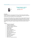
Parts
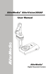
The illustrations below identify the parts of AVerVision300AF.
.
.
: '(1) Camera head .
(2}LEDlight module
(3) Camera lens' .
(4) Control panel
--------
(5) Arm
(6)' Left panel
(7) IR sensor . .
(1 )
.:(8)' Rear panel
.....
(9) Right panel
(10)
.•• (5)
(6)
(7)
(2) _~"
Rower button
.
.
(11), Security slot
(3) _----'r-'III
(8)
(12) ,DG12V port
. (13) Light box power
,
.port
(14)
--+-~~
(4)
(9)
VGA output port
.(15)'VGAinput
port
(16)
S-Video output port
(17)
Composite video
output port
Right Panel
(10)
(18) ,TV/RGB display
switch
(19) DVloutput
,
.0:,
port
(20) . USB port
Rear Panel
(14 )
(12)
. (15)
(13) •
Left Panel
(16)
(17)
(18)
3
(19)
(20)
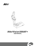
Making the Connections
The ports on the back and side panel of the AVerVision300AF enable
you to connect the unit to a computer, graphics display monitor or
LCD/DLP projector, TV or other device. Illustrated below are the ports
that are located at the back and side panel of the AVerVision300AF
with their corresponding labels.
Port
Description
(1) Antitheft Slot
Attach a Kensington compatible security lock or
antitheft device.
(2) DC 12V (input)
Connect the power adapter into this port.
(3) Light Box Port
Plug the optional light box into this port.
(4) VGA IN Port
Input RGB signal from a computer or other
sources and actively pass it through to the VGA
output port only.
Connect this port to the VGA output port of the
computer.
(5) VGA OUT Port
Output RGB signal from the camera, VGA input
port, or the captured images from the memory on
a VGAlMac monitor or LCD/DLP projector.
(6) TV/RGB Switch
Set to select the between RGB (VGA Out) or TV
(Composite Video/S-Video Out) display output.
(7) VIDEO Port
(RCAlComposite)
Output the signal from the camera or the
captured images from the built-in memory on TV
or video equipment.
(8) S-VIDEO Port
Output the signal from the camera or the
captured images from the memory on TV or
video equipment.
(9) DVI Port
Output video signal from the camera, or the
captured images from the memory on an LCD
monitor or LCD/DLP projector with DVI interface.
(10) USB Port
Use AVerVision300AF as a USB Camera or
Image Download allowing you to transfer the
captured images to and from the
AVerVision300AF built-in memory and PC.
5
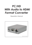
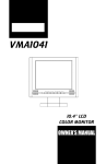
Connecting a VGA, Mac Display
Monitor or LCD/DLP Projector
Locate the RGB (VGA) input port of the display device. If you are not
sure, please refer to the user manual of the device.
1-]
Make sure the TV/RBG switch is set to RGB.
:
: OIJJJ
IID-----mJillIO
RGB (VGA) cable
(not supplied)
~.•••••••••••••••••••••••••••••••.••••••••.•••.••
::
~if>]
••••••
,131=0
LCDIDLP projector
\.CRT monitorfl
+
.
'.
LCD monitor
Monitor Adapter
(not supplied)
MAC monitor
Connecting a VGA Monitor or LCD/DLP
Projector with DVI interface
Locate the DVI input port of the display device. If you are not sure,
please refer to the user manual of the device.
1-]
Make sure the TV/RBG switch is set to RGB.
........................................
················I~1'l(
)[J.----.rJI(
DVI cable
(not supplied)
7
LCD Monitor
with DVI interface
.1.1
LCD/DLP projector
with DVI interface
Connecting
Macintosh
an IBM Compatible
PC or
Computer
Locate the RGB video output port of the computer or laptop to display
your PC presentation on screen. AVerVision300AF supports active
pass-thru connectivity, wherein the video signal from the VGA input port
is continuously streamed to VGA output port and displayed on screen
even when the AVerVision300AF is turned off.
Computer
•••••••••••••
Q
Ooootm:-----:m:JIlllO
:::::::::~
Computer extension cable
(VGAcable)
,_._._
....
L._.~
Laptop
_._1
+
Monitor Adapter
(not supplied)
MAC
Connecting
Connection
a Computer via USB
Locate the USB port of the computer or laptop. This enables you to use
AVerVision300AF as a USB Camera or to transfer the captured images
from the built-in memory to your computer. Also see "Transfer Image
from AVerVision300AF to PC" and refer to the bundled software user
guide in the CD.
MAC
8
Installing
the Optional
Light Box
Connecting an optional light box enables you to view x-rays,
transparencies and negative slides.
~~-rTURNON
Connecting
to a Microscope
Connecting the AVerVision300AF to a microscope enables you to
examine microscopic objects on a big screen without straining your
eyes.
,.~~--~
~
'"""'i7~
I\~
r'~J!\
I
)
7
f}
\
~
~
~
Microscope
Coupler
r: '0
~
Press the latch to detach
the light module from
Microscope
Adapter
V
r? . the ~amera ~,ead
~{T--~
}
'---t
---.LJJ
~
LED Light Module
Microscope
9
Setting
Up AVerVision300AF
This section provides useful tips on how to adjust the
AVerVision300AF to meet your needs.
Camera Head
The camera head can be rotated 135 degrees from left to right. You
can also manually adjust the focus from here to improve the quality of
the pictures.
fA Adjust the angle here
at the ridged side
~t2
-r--~~~-
Mechanical
Arm
The mechanical arm design allows you to project an image to its full
height for full A4 paper landscape viewing.
o
10
ExtendablEl up to
122mm (4.8 in)
long.
Function
Description
(6) FREEZE
Toggle to pause or resume the display
image. (camera mode only)
(7) AUTO FOCUS
Adjust the focus automatically.
(8) MENU
Pull up and exit the OSD main-menu and
sub-menu.
(9) ZOOM +/-
Zoom in and zoom out the picture digitally
in Playback mode.
When it reaches the maximum
AVERZOOM level of about 200%, you can
still continue to digitally zoom in the image
up to 1600%.
(10) .••.•...••• ~
- Pan the mage to the left, right, up, down
when zoom in mode.
- Make a selection on the main menu and
sub-menu. (See Menu Functions, for more
details)
-
Make a selection in 16-thumbnail
images and press
selected image.
to view the
LED Panel
The LED on the front panel of AVerVision300AF indicates the status of
the unit.
Color
Description
The unit is operated with VGA output.
Green
Orange
Red
The unit is operated with TV output
The unit is in standby mode.
15
Name
Button
(17) CAPTURE
(19) MIRROR
(20) DELETE
Function
CAPTURE
OC~
•
Capture a still image. The captured
image is saved in the built-in memory
at 1024 x 768 resolution .
Flip the image in Camera mode.
Remove the selected picture from the
built-in memory permanently in
Playback mode.
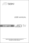
Touch Button Control Panel
The touch button control panel located on the top side of the
AVerVision300AF provides quick access to commonly used functions.
(2)-----
~-_(1)
(3) -----....
--(10)
(4) .--
(9)
(8)
(6)
-"'(7)
-
Function
Description
(1) CAMERA MODE
Display image from the document camera.
(2) PC MODE
Display video Signal from the RGB input
port.
(3) PLAYBACK
MODE
Display captured images from the built-in
memory in either 16-thumbnail mode or full
screen mode.
(4) CAP/DEL
Capture a still image. The captured image
is saved in the built-in memory at 1024 x
768 resolution. Remove the selected
picture from the built-in memory
permanently in Playback mode.
(5)
Change live image in BW, Negative or
EFFECT
Color. (camera mode only)
14
Name
(6) TIMER
(7) REVERSE
(8 & 18)
PAGE UP/
DOWN
(9) NIGHT
VIEW
(10) FREEZE
(11) AUTO
FOCUS
(12) FOCUS
6./\1
Button
•
•
••••
•
••
••
••
PGUP
@!)
Function
Display, start and hide the on-screen
display timer. (See Timer Function
for more details)
Rotate the image by 180°. (camera
mode only)
Display previous and next set of
16-thumbnail images.
PGDN
)
Turn on/off Night View.
Use Night View when you are
presenting in a low-light condition.
The display image appears in low
frame rate.
Toggle to pause or resume the display
image. (camera mode only)
Adjust the focus automatically.
Adjust the focus manually .
FOCUS
)
(13) ZOOM +/-
1=1]
ZOOM
f;M]
(14) ZOOM
RESET
(15) MENU
•
(16) .• T ~
(~ ENTER)
Zoom in and zoom out the picture
digitally in Playback mode.
When it reaches the maximum
AVERZOOM level of about 200%, you
can still continue to digitally zoom in
the image up to 1600%.
Return to normal view (1x).
Pull up and exit the OSD main-menu
and sub-menu.
- Pan the mage to the left, right, up,
down when zoom in mode.
- Make a selection on thE~main
menu and sub-menu. (SeE!Menu
Functions, for more details)
-
Make a selection in 16-thumbnail
images and press
selected image.
13
to view the
Using the Infrared
Remote Control
Use the AVerVision300AF
Remote Control to enhance your presentation,
switch between (3) three presentation modes and access various
features. To use the remote control, first insert the batteries (2 size "AM"
batteries are provided) into the battery compartment at the back of the
remote. Use the figure and descriptions below to help you use the
remote control.
(2)
(3)
(1 )
(4)
(20)
(5)
(6)
(19)
(18 )
(7)
(17)
(8)
(9)
(16)
(10)
(15 )
Name
(1) POWER
(2) CAMERA
MODE
(3} PC MODE
(4) PLAYBACK
MODE
(5) EFFECTS
(11)
(14 )
(12)
(13 )
Button
(9
e
f)
e
•
12
Function
Turn the unit on/off.
Display image from the document
camera.
Display video signal from the RGB
input port.
Display captured images from the
built-in memory in either 16-thumbnail
mode or full screen mode .
Change live image in BW, Negative or
Color. (camera mode only)