1
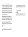
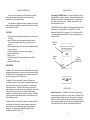
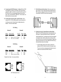
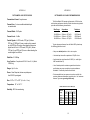
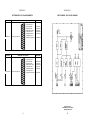
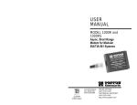
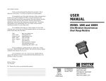
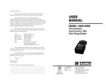
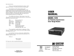
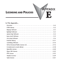
USER
MANUAL
MODEL 1003
and 1003S
Asynchronous,
2-Wire, Carrier
Sense Short Range
Modem
Part #07M1003-B
Doc. #050021UB
Revised 4/28/98
An ISO-9001
Certified Company
SALES OFFICE
(301) 975-1000
TECHNICAL SUPPORT
(301) 975-1007
http://www.patton.com
1.0 WARRANTY INFORMATION
1.3 SERVICE
Patton Electronics warrants all Model 1003 components to be free
from defects, and will—at our option—repair or replace the product should
it fail within one year from the first date of shipment.
This warranty is limited to defects in workmanship or materials, and
does not cover customer damage, abuse or unauthorized modification. If
this product fails or does not perform as warranted, your sole recourse
shall be repair or replacement as described above. Under no condition
shall Patton Electronics be liable for any damages incurred by the use of
this product. These damages include, but are not limited to, the following:
lost profits, lost savings and incidental or consequential damages arising
from the use of or inability to use this product. Patton Electronics
specifically disclaims all other warranties, expressed or implied, and the
installation or use of this product shall be deemed an acceptance of these
terms by the user.
1.1 RADIO AND TV INTERFERENCE
The Model 1003 generates and uses radio frequency energy, and if
not installed and used properly—that is, in strict accordance with the
manufacturer's instructions—may cause interference to radio and
television reception. The Model 1003 has been tested and found to
comply with the limits for a Class A computing device in accordance with
the specifications in Subpart J of Part 15 of FCC rules, which are designed
to provide reasonable protection from such interference in a commercial
installation. However, there is no guarantee that interference will not occur
in a particular installation. If the Model 1003 does cause interference to
radio or television reception, which can be determined by disconnecting
the RS-232 interface, the user is encouraged to try to correct the
interference by one or more of the following measures: moving the
computing equipment away from the receiver, re-orienting the receiving
antenna and/or plugging the receiving equipment into a different AC outlet
(such that the computing equipment and receiver are on different
branches).
All warranty and nonwarranty repairs must be returned freight
prepaid and insured to Patton Electronics. All returns must have a
Return Materials Authorization number on the outside of the shipping
container. This number may be obtained from Patton Electronics
Technical Service at
telephone: (301) 975-1007,
web address: http://www.patton.com;
email: [email protected].
NOTE: Packages received without an RMA number will not be
accepted.
Patton Electronics’ technical staff is also available to answer any
questions that might arise concerning the installation or use of your
Model 1003. Technical Service hours: 8AM to 5PM EST, Monday
through Friday.
1.2 CE NOTICE
The CE symbol on your Patton Electronics equipment indicates that it
is in compliance with the Electromagnetic Compatibility (EMC) directive
and the Low Voltage Directive (LVD) of the Union European (EU). A
Certificate of Compliance is available by contacting Patton Technical
Support.
1
2
GENERAL INFORMATION
Thank you for your purchase of this Patton Electronics product.
This product has been thoroughly inspected and tested and is
warranted for One Year parts and labor.
If any questions or problems arise during installation or use of this
product, please do not hesitate to contact Patton Electronics Technical
Support at (301)-975-1007.
FEATURES
• "Carrier Sense" automatically detects presence of received signal
on the line
• Ideal for UNIX and similar environments where host needs to
receive a carrier signal before sending a "log-on" screen to a
terminal
• Allows troubleshooting of a line: loss of carrier indicates problem at
remote connection
• Full Duplex operation over coax or a single twisted pair.
• Data rates to 19,200 bps
• Range to 1 mile.
• No AC power required: draws necessary power from RS-232
signals.
• External DCE/DTE switch
CONFIGURATION
Configuring the DTE/DCE Switch. Terminals (DTEs) want to "talk" to
modems (DCEs), not to other terminals. This is because terminals and
modems talk to each other on complementary pins. Terminals talk on
pin 2, while modems talk on pin 3. Similarly, terminals listen on pin 3,
while modems listen on pin 2.
The DTE/DCE switch on the Model 1003 determines whether the Model
1003 "thinks" it's a modem (DCE) or a terminal (DTE). If you are
connecting the Model 1003 to a terminal or PC, set the switch to DCE.
If you are connecting the Model 1003 to a modem or multiplexer, set
the switch to DTE.
DCE/DTE
Switch
Terminal
Block
Surge
Suppressors
(1003S only)
DESCRIPTION
The Model 1003 is a Carrier Sense Short Range Modem that connects
computers and terminals over a single coax or single twisted pair cable.
The Model 1003 derives necessary power for operation from the data
and control voltages on the RS-232 interface.
The Model 1003 with "carrier sense" is ideal for UNIX and other
environments in which the host requires a carrier detect signal on pin 8
before it sends a "log-on" screen to the terminal. The carrier sense
feature works like this: The Model 1003 monitors its received line.
When a signal is received from the line, pin 8 (CD) tells the host to send
a "log-on" screen to the terminal. If the received signal is lost or
interrupted, the carrier detect signal is held low to the host. The Model
1003's carrier sense feature makes it ideal for trouble shooting in nonUNIX applications as well.
The Model 1003S is a surge protected version of the Model 1002 that
uses the latest in bi-directional, clamping, transient suppressors to
protect itself and connected equipment against harmful transient
discharges. For surge handling capability, the Model 1003S is
compliant with IEC 801.5 level 2, 1kV.
3
DCE
DTE
INSTALLATION
General Instructions. The Model 1003 is intended for point-to-point
communication over a single coax or one-pair cable. Two Model 1003's
are needed for each communication link: one at each end of the cable.
Please be sure that the cable you use has no equalizers, conditioners,
or other equipment installed that could affect the signal passed between
the two Model 1003s--they need dry, unconditioned metallic cable.
4
A. Connecting to the RS-232 Interface. The Model 1003 and 1003S
are designed to plug directly into the DB-25 (RS-232) interface of
a terminal or modem. Connection may also be made using a short
RS-232 cable. Note: The connecting cable must have at least
pins 2,3 and 7 wired STRAIGHT THROUGH. For best results, this
cable should be as short as possible.
C. Two-Wire Connection Using Coax. When using coax for twowire connection, the coax cable should be terminated with male
BNC connectors. Simply twist these onto the female connectors
on the Model 1003/1003S units and start computing!
B. Two-Wire Connection Using RJ-11 and RJ-45 Jacks. When
using the RJ-11 or RJ-45 modular jacks for two-wire connection, it
is necessary to employ "straight through" cabling between the
modems. Pin-outs are shown below:
RJ-11 Wiring
Modem #1
Modem#2
SIGNAL
PIN# COLOR*
COLOR*
PIN# SIGNAL
DATA
GND
3
4
Green
Red
3
4
Green
Red
DATA
GND
RJ-45 Wiring
1.
Modem #1
Modem#2
SIGNAL
PIN# COLOR*
COLOR*
PIN# SIGNAL
DATA
GND
4
5
Red
Green
4
5
Red
Green
D. Two-Wire Connection Terminal Blocks and Strain Relief.
Model 1003 and 1003S modems that are not equipped with coax
connectors or modular jacks allow for two-wire connection via
internal terminal blocks. An external strain relief collar--integrated
into the plastic case--holds the cable securely in place so that it
won't pull loose from the terminal block connections. Follow these
step-by-step instructions to wire up the Model 1003/1003S using
the terminal block/strain-relief assembly:
Open the plastic case by gently inserting a screw driver
between the DB-25 connector and the lip of the plastic case.
There is no need to worry about breaking the plastic--just be
careful not to bend the metal DB-25 connector.
DATA
GND
* Standard Color Codes - Yours may be different
1 - Blue
2 - Orange
3 - Black
4 - Red
5 - Green
6 - Yellow
7 - Brown
8 - Slate
1 - Blue
2 - Yellow
3 - Green
4 - Red
5 - Black
6 - White
AT&T Standard pins/colors
5
6
2.
Strip the outer insulation from the twisted pair about one inch
from the end.
3. Strip back the insulation on each of the two wires about .25",
4.
6.
Insert the strain relief assembly with the wire going through it
into the slot in the bottom half of the modem case and seat it
into the recess in the case. (If the telephone wire is too thin to
be held by the strain relief assembly, use tape to increase its
diameter. If the wire is too large, it may be necessary to drill
out the strain relief slightly.
6.
BEND the top half of the case as necessary to place it over
the strain relief assembly. Do not snap the case together yet.
7.
Insert one captive screw through a saddle washer and then
insert the captive screw with the washer on it, through the hole
in the DB-25 end of the case. Snap that side of the case
closed. Repeat the process for the other side. This completes
the installation process.
Insert into the proper terminal post and tighten the screw. Be
sure that all cabling between the short range modems is
straight through.
Signal (S)
Ground (G)
Signal (S)
Ground (G)
NOTE: Depending on version, terminal post locations may
vary.
5.
Place the 2 halves of the strain relief assembly on either side
of the telephone wire and press together very lightly. Slide the
assembly so that it is about 2 inches from the terminal posts
and press together firmly.
7
8
APPENDIX A
APPENDIX B
PATTON MODEL 1003 SPECIFICATIONS
PATTON MODEL 1003 CABLE RECOMMENDATIONS
Transmission Format: Asynchronous
Transmit Line: 2 wire unconditioned twisted pair
or coaxial cable
Transmit Mode: Full Duplex
Transmit Level: -0 dBm
Control Signals: In DCE mode, CTS (pin 5) follows
RTS (pin 4), DSR (pin 6) turns on when unit is powered
up, and DCD (pin 8) turns on after detecting the receive
signal from the line. In DTE mode, RTS (pin 4) follows
CTS (pin 5), and DTR (pin 20) turns on after detecting the
receive signal from the line.
The Patton Model 1003 operates at frequencies of 20kHz or less
and has been performance tested by Patton technicians using twistedpair cable with the following characteristics:
Wire Gauge
Capacitance
Resistance
19 AWG/.9mm
22 AWG/.6mm
24 AWG/.5mm
83nf/mi or 15.72 pf/ft.
83nf/mi or 15.72 pf/ft.
83nf/mi or 15.72 pf/ft.
.0163 Ohms/ft.
.0326 Ohms/ft.
.05165 Ohms/ft.
To gain optimum performance from the Model 1003, please keep
the following guidelines in mind:
• Always use twisted pair wire—this is not an option.
• Use twisted pair wire with a capacitance of 20pf/ft or less.
Data Rate: 0-19.2Kbps
Surge Protection: Compliant with IEC 801.5 level 2, 1kV (Model
1003S Only)
• Avoid twisted pair wire thinner than 26 AWG (i.e. avoid higher
AWG numbers than 26)
• Use of twisted pair with a resistance greater than the above
specifications may cause a reduction in maximum distance
obtainable. Functionality should not be affected.
Range: Up to 1 mile
Power: None Required, derives required power
from RS-232 input signals
Size: 2.20" x 1.75" x 0.75" (5.6 x 4.4 x 1.9 cm)
• Environmental factors too numerous to mention can affect the
maximum distances obtainable at a particular site. Use “maximum
distance” figures as a general guideline only.
Temperature: 32° to 140° F
Model 1003 Distance Table in Miles (km)
Humidity: 95% Non-condensing
Data Rate
(bps)
19,200
9,600
4,800
2,400
1,200
9
Wire Gauge
19 AWG
( 0.9 mm)
2.2(3.5)
3.0(4.8)
4.3(6.4)
5.3(8.5)
5.6(9.0)
24 AWG
(0.5 mm)
1.6(2.6)
2.1(3.4)
2.6(4.2)
2.8(4.5)
2.8(4.5)
10
26 AWG
(0.4 mm)
1.2(1.9)
1.6(2.6)
1.7(2.7)
1.8(2.9)
1.8(2.9)
DIRECTION
To Model 1003
DIRECTION
APPENDIX C
APPENDIX B
PATTON MODEL 1003 PIN ASSIGNMENTS
PATTON MODEL 1003 BLOCK DIAGRAM
STANDARD "DCE" SETTING
1- (FG) Frame Ground
2- (TD) Transmit Data
3- (RD) Receive Data
4- (RTS) Request to Send
5- (CTS) Clear to Send
6- (DSR) Data Set Ready
7- (SG) Signal Ground
8- (DCD) Data Carrier Detect
Data Term. Ready (DTR) - 20
STANDARD "DTE" SETTING
1- (FG) Frame Ground
2- (TD) Transmit Data
3- (RD) Receive Data
4- (RTS) Request to Send
5- (CTS) Clear to Send
6- (DSR) Data Set Ready
7- (SG) Signal Ground
8- (DCD) Data Carrier Detect
From Model 1003 Data Term. Ready (DTR) - 20
DIRECTION
To Model 1003
From Model 1003
To Model 1003
From Model 1003
From Model 1003
From Model 1003
DIRECTION
From Model 1003
To Model 1003
From Model 1003
To Model 1003
To Model 1003
To Model 1003
Copyright © 1998
Patton Electronics Company
All Rights Reserved
11
12