1
Dear Owner,
Thank you for selecting a Recreational Vehicle engineered and manufactured by EverGreen Recreational
Vehicles LLC. EverGreen Recreational Vehicles LLC is a progressive corporation committed to
environmentally responsible construction products and techniques. We invite you to join us in protecting the
earth’s environment by recycling whenever possible.
It is recommended you read this manual prior to operation of the vehicle. Any unanswered questions
regarding the vehicle should be directed to either your selling dealer or EverGreen RV prior to use of the
vehicle. Please know that in the interest of full customer satisfaction, EverGreen RV and its dealer group
stand ready, willing and able to assist with any questions you may have.
It is the goal of EverGreen RV that this vehicle provides many years of enjoyment and pleasant memories for
you, your family, and your friends.
Happy Camping!
PRODUCT INFORMATION SPECIFICATION DISCLAIMER
The information contained within this manual is as accurate as possible at time of printing and generally reflects features, designs,
specifications, and components available at that time. EverGreen Recreational Vehicles LLC reserves the right to make changes to
specifications, features, designs and components at any time without any notification. All information printed within this manual is
subject to change after date of printing. As a result of continual product changes throughout the production year and model year,
and inadvertent transcription errors, this information may not be the most current information available at time of purchase.
Information contained within this manual may reflect both standard and optional features which may not be included in your
vehicle.
In the event you are not the first owner of the vehicle, this manual may not reflect alterations and options added by previous owners .
Copyright © 2011 by EverGreen Recreational Vehicles LLC. All rights reserved. No part of this publication may be reproduced,
adapted, or translated in any form without the specific written permission of EverGreen Recreational Vehicles LLC.
0209-3/ 03-11/12-11
2
Product Series
Dealership Name
City
Owner Email Address
State
Address
City
Model
Zip
State
EverGreen Recreational Vehicles LLC
52886 State Road 13
PO Box 52
Middlebury, IN 46540
574-825-7745 Phone
574-825-7128 Facsimile
www.goevergreenrv.com/registration
Plus 1
Plus 2
Other
Circle Coverage and enclose payment
if selecting Plus 1 or Plus 2
Standard
Zip
Model Year
Dealer Sales Representative Name
Note: Owner information will remain confidential
Serial Number (VIN)
Within 10 days of purchase, please return this completed form and the Warranty and Product acknowledgement form to:
Purchaser’s Signature(s)
Owner Telephone Number
! Mr. ! Mrs. ! Ms. Purchaser’s Name (Last, First, Middle)
Date of Purchase
OWNER REGISTRATION CARD
THIS PAGE LEFT BLANK INTENTIONALLY
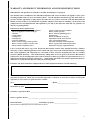
WARRANTY AND PRODUCT INFORMATION ACKNOWLEDGEMENT FORM
IMPORTANT: The purchaser is required to read this document prior to signing it.
The checklist below, in addition to the individual component and owner’s manuals, is designed to assist you in
becoming familiar with your new recreational vehicle. You, the purchaser should not sign this form until: (1)
you have had the opportunity to fully inspect the entire RV; (2) you have reviewed, read and understand the
limited warranty terms; (3) you find the RV acceptable, complete, clean, and free of damage; (4) all features and
components have been demonstrated and explained to you; and (5) the dealer has answered any questions you
may have regarding the RV.
Inspection by Dealer and Purchaser
Approve of general interior finish and condition
Operate all appliances (electrical and gas)
1. Furnace
2. Water Heater
3. Range/oven
4. Refrigerator
5. Roof air conditioner
Review of battery charge system operation
Review of owner’s manual, warranty terms,
and preventative maintenance chart
Approve of general exterior condition
Review propane gas safety
Review wheel lug tightening process
and frequency.
Review tire inflation test process.
Explanation of fresh water and waste
water systems and operations
Operation of all audio. visual components
Review of proper hitch connection procedure
Explanation of proper weight distribution
I have received and read a copy of the EverGreen Recreational Vehicles LLC Limited Warranty (“Limited
Warranty”) before completing purchase of the vehicle and agree to the terms contained therein. I acknowledge
that certain appliances and components are warranted by their respective manufacturers and are excluded
from the Limited Warranty. I also understand the selling dealer is not an agent for EverGreen Recreational
Vehicles LLC, but is an independent entity with no authority to make any promises or representations for or on
behalf of EverGreen Recreational Vehicles LLC. I acknowledge this form is for product registration purposes
and failure to return this form does not reduce the warranty period.
Purchaser: My dealer and I have completed the new vehicle inspection and have noted the following:
Dealer: The purchaser has participated in a feature and operational demonstration of the vehicle; and has been given the
opportunity to inspect the vehicle; has been provided opportunity to add notes in section above; and has been provided
opportunity to receive answers to questions relative to the RV.
VIN:
Model ____________________________
Retail Delivery Date:
Purchaser’s signature & Date _____________________________________________________________
Dealer’s signature & Date ________________________________________________________________
Dealership name _____________________ Dealership rep (print) ______________________________
Please forward this completed form to EverGreen Recreational Vehicles.
5
THIS PAGE LEFT BLANK INTENTIONALLY
6
This section may be used to record your purchase and contact information
Date of Purchase
Serial Number
Model of RV
Model Year
Dealership name and contact information
Salesperson
NOTES
__________________________________________________________________________
__________________________________________________________________________
__________________________________________________________________________
__________________________________________________________________________
__________________________________________________________________________
__________________________________________________________________________
__________________________________________________________________________
__________________________________________________________________________
__________________________________________________________________________
__________________________________________________________________________
__________________________________________________________________________
__________________________________________________________________________
__________________________________________________________________________
__________________________________________________________________________
__________________________________________________________________________
__________________________________________________________________________
__________________________________________________________________________
__________________________________________________________________________
__________________________________________________________________________
7
TABLE OF CONTENTS
OWNER REGISTRATION FORM ………………………………………………………………………….. 3
WARRANTY AND PRODUCT INFORMATION ACKNOWLEDGEMENT FORM……………………... 5
PURCHASE NOTES ………………………………………………………………………………………… 7
COVERAGE PROVIDED........................................................................................................................ 11
WHAT IS NOT COVERED BY THIS LIMITED WARRANTY ........................................................... 12
DISCLAIMER OF INCIDENTAL AND CONSEQUENTIAL DAMAGES .......................................... 13
YOUR OBLIGATIONS ........................................................................................................................... 13
STATUTE OF LIMITATIONS ................................................................................................................ 14
REPORTING SAFETY DEFECTS.................................................................................................. 15
HOW TO OBTAIN SERVICE ......................................................................................................... 15
WARRANTY SERVICE WHILE TRAVELING ............................................................................ 15
SCHEDULING A SERVICE APPOINTMENT .............................................................................. 15
OWNER OBLIGATIONS – Important, Please Read ....................................................................... 16
DEALER OBLIGATIONS ............................................................................................................... 16
VEHICLE IDENTIFICATION NUMBER AND DATA PLATES ......................................................... 16
SYMBOLS USED WITHIN THIS MANUAL ........................................................................................ 17
BECOMING FAMILIAR WITH YOUR NEW RECREATIONAL VEHICLE ..................................... 17
GENERAL SAFETY PRECAUTIONS ................................................................................................... 17
EXIT WINDOW ............................................................................................................................... 17
PROPANE SAFETY ........................................................................................................................ 18
ELECTRICAL SAFETY .................................................................................................................. 19
FIRE SAFETY .................................................................................................................................. 19
SMOKE DETECTOR....................................................................................................................... 19
CARBON MONOXIDE DETECTOR ............................................................................................. 19
PROPANE GAS DETECTOR ........................................................................................................ 20
FIRE EXTINGUISHER OPERATION ............................................................................................ 21
DRIVING SAFETY.......................................................................................................................... 21
DRIVING EMERGENCIES............................................................................................................. 22
REFUELING YOUR TOW VEHICLE ............................................................................................ 22
CONDENSATION AND HUMIDITY .................................................................................................... 22
MOLD AND MILDEW .................................................................................................................... 23
CHEMICAL SENSITIVITY .................................................................................................................... 23
FORMALDEHYDE ......................................................................................................................... 23
VENTILATING YOUR RV ............................................................................................................. 24
WHEELS AND TIRES............................................................................................................................. 24
TIRES ............................................................................................................................................... 24
WHEEL LUG NUT TORQUE – Critically Important! .................................................................... 25
CHANGING A SPARE TIRE .......................................................................................................... 25
REPLACEMENT WHEEL REQUIREMENT ................................................................................. 26
TIRE INFLATION ........................................................................................................................... 26
TIRE TREAD ................................................................................................................................... 27
TIRE REPAIR .................................................................................................................................. 27
TIRE BALANCE .............................................................................................................................. 27
WHEEL ALIGNMENT .................................................................................................................... 27
HITCH SELECTION................................................................................................................................ 28
HITCHING A TRAVEL TRAILER ......................................................................................................... 28
8
WEIGHT SECTION ................................................................................................................................. 29
PROCEDURES FOR WEIGHING YOUR TRAILER ............................................................................ 29
HITCH WEIGHT.............................................................................................................................. 29
AXLE WEIGHT ............................................................................................................................... 29
TOTAL WEIGHT OF TRAILER ..................................................................................................... 29
TOTAL WEIGHT OF TRAILER AND TOW VEHICLE ............................................................... 29
WEIGHT DISTRIBUTION AND LOADING ......................................................................................... 29
LEVELING THE RV ............................................................................................................................... 30
ELECTRICAL SYSTEM ......................................................................................................................... 31
120-VOLT SHORE POWER ELECTRICAL SYSTEM ................................................................. 31
120-VOLT ELECTRICAL LOAD CENTER (Breaker Box) .......................................................... 31
12-VOLT POWER SYSTEM ........................................................................................................... 31
12-VOLT FUSES ............................................................................................................................. 31
120-VOLT SHORE POWER CORD CONNECTION PROCESS. ................................................. 32
GROUND FAULT CIRCUIT INTERRUPTER (GFCI).................................................................. 33
MANAGING YOUR ELECTRICAL USAGE ................................................................................ 34
PROPANE SYSTEM ............................................................................................................................... 35
REGULATORS ................................................................................................................................ 35
FILLING PROPANE CYLINDERS ................................................................................................ 35
PLUMBING SYSTEMS........................................................................................................................... 36
FRESH WATER AND WATER PUMP SYSTEM ......................................................................... 36
SANITIZING THE FRESH WATER SYSTEM.............................................................................. 37
WATER HEATER PRESSURE RELIEF VALVE.......................................................................... 37
WATER HEATER BYPASS VALVE ............................................................................................. 38
WATER LINE DRAINS .................................................................................................................. 38
WINTERIZATION OF PLUMBING SYSTEM .............................................................................. 39
WASTE WATER TANKS ....................................................................................................................... 39
EMPTYING THE WASTE WATER TANKS ................................................................................. 39
SLIDE-OUT ROOM SYSTEMS.............................................................................................................. 40
CARE AND MAINTENANCE ................................................................................................................ 41
EXTERIOR, CARE AND MAINTENANCE .................................................................................. 42
EXTERIOR WALL SURFACES ..................................................................................................... 42
ROOF SURFACES........................................................................................................................... 42
WINDOWS ....................................................................................................................................... 42
SEALANTS. EXTERIOR ................................................................................................................ 42
WINDOWS ....................................................................................................................................... 43
FRAME/CHASSIS ........................................................................................................................... 43
TIRES/WHEELS .............................................................................................................................. 43
SAFETY CHAINS ........................................................................................................................... 43
HITCH JACK ................................................................................................................................... 43
STEPS ............................................................................................................................................... 43
HITCH COUPLER ........................................................................................................................... 43
WHEEL LUG NUT TORQUE ......................................................................................................... 43
TIRE INFLATION ........................................................................................................................... 44
WHEEL BEARINGS........................................................................................................................ 44
LEAF SPRING EQUALIZER .......................................................................................................... 45
BRAKE ADJUSTMENT .................................................................................................................. 45
LIGHTING ....................................................................................................................................... 45
CARE AND MAINENANCE, CONTINUED
9
BATTERY, DEEP CYCLE .............................................................................................................. 45
BATTERY TESTING AND MAINTENANCE .............................................................................. 46
INTERIOR CARE AND MAINTENANCE ............................................................................................ 46
CABINETS ....................................................................................................................................... 46
WALL AND CEILING SURFACES ............................................................................................... 46
COUNTERTOP SURFACE ............................................................................................................. 46
WINDOW COVERINGS ................................................................................................................. 47
BEDSPREAD ................................................................................................................................... 47
UPHOLSTERY ................................................................................................................................ 47
BATHTUB/SHOWER & SINK ....................................................................................................... 47
MIRRORS AND GLASS ................................................................................................................. 47
FLOORING, VINYL LINOLEUM .................................................................................................. 47
FLOORING, CARPET ..................................................................................................................... 47
PRE-TRIP CHECKLIST .......................................................................................................................... 48
MAINTENANCE LOG ............................................................................................................................ 49
PRESCRIBED MAINTENANCE CHART ............................................................................................. 50
COMPONENT SUPPLIER CONTACT INFORMATION ….…………………………………………51
10
EVERGREEN RECREATIONAL VEHICLES LLC
LIMITED WARRANTY
COVERAGE PROVIDED
Twelve (12) Month Limited Warranty
EverGreen Recreational Vehicles LLC (“EverGreen RV”) warrants that it will repair or replace
defects in material or workmanship in any components of a recreation vehicle (“vehicle”)
manufactured by EverGreen RV for a period of twelve (12) months from the date the vehicle is first
delivered to the original retail purchaser, subject to the other terms and conditions of this Limited
Warranty.
Thirty-Six (36) Month Limited Warranty
EverGreen RV warrants that it will repair or replace defects in the aluminum skeleton structure of the
floor, sidewalls, roof and front and rear walls of the vehicle for a period of thirty-six (36) months
from the date the vehicle is first delivered to the original retail purchaser, subject to the other terms
and conditions of this Limited Warranty.
Terms and Conditions of Coverage
This Limited Warranty extends solely to the first retail purchaser of the vehicle and is not
transferable to subsequent owners. EverGreen RV makes no warranties or representations other than
as set forth in this Limited Warranty. In order to obtain coverage under this Limited Warranty, you
must notify an authorized EverGreen RV dealership or EverGreen RV of the warrantable issue no
later than ten (10) days following expiration of this Limited Warranty. Repair or replacement of
defective components is the sole remedy under this Limited Warranty. This Limited Warranty does
not extend to future performance of the vehicle. EverGreen RV shall be entitled to condition
warranty coverage under the thirty-six (36) month limited warranty on purchaser allowing EverGreen
RV to transport the vehicle to its facilities in Middlebury, Indiana for purposes of the repairs.
EverGreen RV reserves the right to use new or remanufactured parts of similar quality and
appearance. No person or entity has authority to alter the terms and conditions of this Limited
Warranty, and EverGreen RV shall not be bound by any representations or warranties of its dealers,
or any other person or entity.
LIMITATION OF IMPLIED WARRANTIES
Implied warranties arising under applicable state laws, if any, including but not limited to implied warranties
of merchantability or fitness for a particular purpose, are hereby disclaimed or, if disclaimer is not permitted
by applicable law, are limited in duration to the applicable term of this Limited Warranty, and are limited in
scope of coverage to the scope of coverage under the Limited Warranty. Some states do not allow
limitations on how long an implied warranty lasts, so the above limitation may not apply to you.
11
WHAT IS NOT COVERED BY THIS LIMITED WARRANTY
This Limited Warranty does not provide coverage for any of the following:
1.
The stereo, televisions, range/stove, furnace, refrigerator, water heater, microwave, air
conditioner, power converter, water pump, toilet, awning, LP tanks, batteries, generator,
slide-out mechanism, tires and other materials, parts, and components manufactured and
warranted by persons or entities other than EverGreen RV. EverGreen RV may be permitted
to administer some of the warranties on these components. Consult those separate warranties
for further information. Administration of those warranties does not result in EverGreen RV
being a warrantor under those warranties.
2.
Chassis of the vehicle, including but not limited to the frame and axles, which is warranted
by its respective manufacturer, and is administered separately from this Limited Warranty;
3.
Any recreation vehicle exported to, primarily used in, or licensed in a country other than the
United States and Canada;
4.
Deterioration or fading due to wear, exposure, or other cause, including but not limited to
rust, cosmetic blemishes, and discoloration;
5.
Normal maintenance and service items, including but not limited to light bulbs, fuses, tire
wear, lubricants, sealant and seals, slide-out adjustments, door and drawer adjustments, and
awning tension;
6.
Vehicles not purchased through on authorized dealer of EverGreen RV vehicles, or
purchased directly or indirectly through auction, salvage, or repossession; and
7.
Defects or damage caused by, in whole or in part, or in any way related to:
A.
B.
C.
D.
E.
F.
G.
H.
I.
J.
K.
L.
M.
N.
Accidents, misuse (including off-road use), theft, or negligence.
Failure to comply with the instructions set forth in any owner’s manual provided with
the vehicle.
Alteration or modification of the vehicle except such alterations or modifications
approved in writing by EverGreen RV.
Acts of God or other environmental conditions, such as lightning, hail, salt, or other
chemicals in the atmosphere.
Failure to properly maintain or service the vehicle, including but not limited to the
maintenance of lubricants, sealants, and seals.
Condensation and the results of condensation including water damage and the growth
of mold or mildew.
Use of the vehicle other than for temporary recreation purposes, including but not
limited to use of the vehicle for residential, disaster relief housing, commercial, or
rental purposes.
The addition of weight to the vehicle that causes the vehicle’s total weight to exceed
applicable vehicle weight ratings, or addition of weight causing improper distribution
of the weight of the vehicle.
Selection, use, and operation of any hitch assembly.
Failure to seek and obtain repairs in a timely manner.
Improper electric power supply or improper vehicle hookup to other facilities.
Failure to properly ventilate the vehicle.
De-icing agents or other chemicals applied to the vehicle.
Acts or omissions of any person or entity other than EverGreen RV.
12
DISCLAIMER OF INCIDENTAL AND CONSEQUENTIAL DAMAGES
EverGreen RV hereby disclaims any and all incidental and consequential damages arising out of or relating
to the vehicle, including expenses such as transportation to and from vehicle dealerships and EverGreen RV
repair facilities, loss of time, loss of pay, loss of use, inconvenience, commercial loss (including lost profits),
towing charges, bus fares, vehicle rental, service call charges, gasoline expenses, incidental charges such as
telephone calls and facsimile transmissions, and expenses for lodging. This disclaimer is independent of any
failure of the essential purpose of any warranties provided to purchaser, and shall survive any determination
that a warranty failed of its essential purpose.
Some states do not allow the exclusion or limitation of incidental or consequential damages, so the above
limitation or exclusion may not apply to you.
YOUR OBLIGATIONS
The retail purchaser is responsible for normal maintenance, as described in owner’s manuals provided with
the vehicle. However, EverGreen RV will provide for minor adjustments, such as adjustments to the slideouts, interior or exterior doors, LP regulator pressure, cabinet latches, plumbing fittings, TV antenna control,
and voids in sealants, for the first ninety (90) days following delivery of the vehicle to the original retail
purchaser.
If an issue arises that you believe is covered by the Limited Warranty, you should contact an authorized
EverGreen RV dealer and give the dealer sufficient information to resolve the matter. If an authorized
EverGreen RV dealer is unable to resolve your issue, you should contact EverGreen RV directly, by mail at
10758 CR 2, P O Box 52, Middlebury, Indiana 46540, by phone at 574-825-4298, or by facsimile at 574825-4299. It is your responsibility to schedule an appointment for repairs and to arrange for transportation of
the vehicle to and from the authorized EverGreen RV dealership or the EverGreen RV repair facility. This
Limited Warranty does not cover on-site service calls.
It is your responsibility to notify an authorized EverGreen RV dealership, or EverGreen RV, of any issue you
believe to be covered by the Limited Warranty, in a timely manner. It is also your responsibility to take
reasonable measures to protect the vehicle from further damage due to any defect that arises.
If you believe that an issue has arisen with respect to the vehicle that is not covered by this Limited Warranty
but is covered by the warranty of another manufacturer, you should review the warranty and other materials
provided to you by that manufacturer in order to determine the procedure to be followed in order to obtain
warranty coverage under that manufacturer’s warranty. If you are unable to obtain contact information for
that manufacturer, an authorized EverGreen RV dealer or EverGreen RV will supply that information to you.
13
STATUTE OF LIMITATIONS
No action may be brought against EverGreen RV for breach of this Limited Warranty, any applicable
implied warranty, or for any other claim relating to the vehicle, more than thirty (30) days after the expiration
of a limited warranty period. In the event both warranty periods are relevant to any claim, the thirty (30) day
period provided for herein shall begin to run, as to any particular component to which the claim relates, at the
end of the limited warranty period for that particular component.
THIS WARRANTY GIVES YOU SPECIFIC LEGAL RIGHTS, AND YOU MAY ALSO HAVE
OTHER RIGHTS WHICH VARY FROM STATE TO STATE.
10758 CR 2
P.O. Box 52
Middlebury, Indiana 46540
574-825-4298 – Telephone
574-825-4299 – Facsimile
www.goevergreenrv.com
14
REPORTING SAFETY DEFECTS
If you believe your vehicle has a defect which could cause a crash or could cause injury or death, you should immediately inform
the National Highway Traffic Safety Administration (NHTSA) and EverGreen Recreational Vehicles LLC.
NHTSA may open an investigation if receiving similar complaints; or a remedy campaign or recall campaign may be issued if it
finds a safety defect exists. Please note NHTSA cannot become involved with non-safety issues between you and your dealer or
between you and EverGreen Recreational Vehicles.
You may contact NHTSA via the toll-free hotline of 1-888-327-4236 (TTY: 1-800-424-9153); or mail at NHTSA Administrator
1200 New Jersey Avenue, S.E. Washington, DC 20590; or via website http://www. Safercar.gov.
HOW TO OBTAIN SERVICE
•
•
•
•
To activate the warranty, complete and return the Owner Registration Card to EverGreen RV within Ten (10) days of
purchase. Note the warranty registration card is located within the EverGreen RV owner’s manual.
Notify your selling dealer, EverGreen RV or one of its authorized, independent dealers, in writing within 10 days of
locating claimed defects within the warranty period.
Promptly schedule a repair appointment with an authorized repair center.
EverGreen RV reserves the right to select the method of repair and repair center. In specific cases, EverGreen RV reserves
the right to arrange transport of the RV to a chosen repair center or to the factory repair center in Middlebury, Indiana.
WARRANTY SERVICE WHILE TRAVELING
In the event you require service while traveling, please contact EverGreen RV or your selling dealer for warranty authorization prior
to repair. Repairs made without prior approval may be subject to reduced or denied reimbursement. Please retain all original parts
replaced during service while traveling. These original parts must be returned to dealer or EverGreen RV for evaluation and
consideration of warranty coverage.
SCHEDULING A SERVICE APPOINTMENT
•
•
•
•
•
•
•
Contact the service center and schedule an appointment.
Provide the service center with your VIN number.
Provide a detailed description of the items you wish to have inspected or repaired. Provide clear and accurate
information as the events surrounding a component failure.
Request clarification of which items are covered by the EverGreen RV limited warranty.
Certain repairs may require the service center to order parts. In most cases the RV will be usable while the parts are
on order. You may find the dealer will ask for you transport the RV to the service center for brief diagnostics then
request the RV be brought back at a later date for installation of the part. You should retain the RV in your possession
when in usable condition.
Inspect repairs upon completion.
Sign the repair order upon satisfactory completion of repair.
Your satisfaction is very important to EverGreen RV. Please immediately contact EverGreen RV if
you experience difficulty in scheduling repairs or are unable to have a warrantable issue resolved
within one repair attempt. Please provide your name, 17 digit vehicle identification number, date
of purchase, and location of purchase when contacting EverGreen RV.
15
OWNER OBLIGATIONS – Important, Please Read
The owner is responsible for proper care and maintenance of the RV as outlined in this manual or
any corresponding component manual.
Normal maintenance, sealant maintenance, and
adjustments to items and components such as, but not limited to; interior and exterior doors,
awnings, renewing of exterior sealants, slide room adjustments, latches, and TV antenna controls
will be performed by the dealer for the first ninety (90) days of warranty coverage; thereafter all
such adjustments become the responsibility of the owner as normal maintenance.
Owner shall be responsible for contacting an authorized service center for purpose of scheduling warranty repairs.
Upon
establishing a repair date, the owner shall assume responsibility for transport of the RV to the designated service center. On-site
service calls are specifically excluded from the limited warranty terms.
Review the owner’s manual information contained within this manual and component information supplied with the RV.
Immediately notifying EverGreen RV of any unresolved warrantable issues.
Complete the warranty and product acknowledgement form.
Notify EverGreen of any changes of in address or contact information. This contact information is important in the event a product
or component recall or service bulletin is issued.
DEALER OBLIGATIONS
Explain proper operation of the recreational vehicle and familiarize the customer with all operations of the components and systems
of the vehicle.
Complete and return the warranty and product acknowledgement form and warranty registration card to EverGreen RV.
Review and explain the warranty terms and obligations.
Review and assist the purchaser in completing the pre-delivery product and warranty acknowledgement form.
Complete and submit the warranty registration form to EverGreen RV within ten (10) days of delivery to purchaser.
Perform any necessary warrantable repairs.
VEHICLE IDENTIFICATION NUMBER AND DATA PLATES
The 17 digit Vehicle Identification Number (VIN) is the serial number or identifier number for your recreational vehicle. This 17
digit VIN is affix to a tag on the left front corner of a travel trailer or on the front portion of left side frame rail on a 5th wheel. The
VIN number is also stamped into the steel framework on left side of the hitch area near the tongue jack or pin box hitch. The VIN
data tag attached to front corner of the left sidewall will also identify the Gross Vehicle Weight Rating (GVWR) and Gross Axle
Weight Rating (GAWR) along with the tire size, tire pressure, and rim size. See the “weight and weight distribution” section for
further information. Please use the last 8 digits of VIN as an identifier when contacting EverGreen RV.
16
SYMBOLS USED WITHIN THIS MANUAL
The below listed safety symbols are used in this manual to identify those areas which may represent personal injury or property
damage risk. Note, regardless of symbol designation, please exercise extreme caution in any potentially dangerous area or task.
DANGER indicates an imminently hazardous situation
which, if not avoided, will result in death or serious
injury.
WARNING indicates a potential hazardous situation
which, if not avoided, could result in death or
serious injury.
CAUTION indicates a potentially hazardous
situation which if not avoided, may result in minor
or moderate injury.
NOTICE
NOTICE indicates a potentially hazardous situation
which if not avoided, may result in property damage?
Additional informational and cautionary labels are affixed in various portions of the RV. These labels are intended to remain
attached to the respective area. Please do not remove these labels.
BECOMING FAMILIAR WITH YOUR NEW RECREATIONAL VEHICLE
In an effort to maximize your enjoyment with the new RV, We suggest you become familiar with the RV by initially planning an
entire weekend of camping in your driveway or in close proximity of your home. This arrangement will allow you the opportunity
to become accustomed to the vehicle as well as learning which supplies and equipment are needed or not needed during use of the
RV. During this “break-in” period, please note any operational questions or difficulties you have encountered. These questions can
them be directed to your dealer or to EverGreen RV for response prior to you next camping event.
GENERAL SAFETY PRECAUTIONS
Do not allow passengers to ride inside the trailer when traveling. The RV is not designed with the
necessary seat belts and may be illegal for passenger transport in most states. Failing to heed this
warning may result in serious injury or death.
EXIT WINDOW
Dependent upon your specific floor plan configuration, your RV will be equipped with exit or egress window(s). These
windows have an “Exit” label directly adjacent to the window and are also easily recognizable by the interior handles or
latches which are red in color. These windows are designed to allow emergency exit of the occupants in the event of a fire or
similar occurrence. To open, unlatch the handles and pivot the window and glass outward on the top hinge. Review the exit
window operation and location with all passengers prior to each trip.
17
Please use extreme caution when using any propane appliance and when attaching or detaching the
propane bottles from the RV. Improper handling of propane and propane system may result in
serious injury or death.
PROPANE SAFETY
•
•
•
•
•
•
•
•
•
•
•
•
•
•
•
•
•
•
The gas system in your RV is designed for use with Propane (LPG) gases only, do not use or connect to natural gas.
Do not smoke cigarette, pipes, or cigars, or provide any open flame in the general area of the propane tanks when
attaching/detaching the tanks.
Propane tanks may only be filled by trained personnel in accordance with NFPA Pamphlet 58, and all local or state codes
and regulations.
Remain at least 30 feet away from the propane filling station during the filling process.
Do not allow the propane tanks to be filled to more than 80% capacity.
Do not use cooking appliances for comfort heating.
Cooking appliances need fresh air for safe operation. Open window or vent prior to operating propane supplied stove or
range. Failure to provide adequate fresh air supply can result in elevated carbon monoxide levels and asphyxiation.
If at any time you smell propane;
1. Immediately extinguish all smoking materials, open flames, and pilot lights.
2. Do not touch any electrical switches or components as arcing may occur.
3. Shut off the gas supply at the propane tank by turning the valve clockwise.
4. Open all entry doors and windows.
5. Do not use the power range hood or power roof vents.
6. Clear the area until the propane odor is no longer apparent.
7. Have the propane systems checked prior to again using the propane system.
Do not store, transport or place propane cylinders inside the RV.
Verify all appliances and appliance gas valves are turned off prior to opening the main valve on the main propane supply
tanks.
Verify the propane regulator vent is clear and free of obstruction.
Do not modify the factory installed propane system.
Maintenance of the propane system is only to be performed by personnel qualified and trained in propane gas systems.
Verify each month that burners and orifices of the propane appliances are clean and free of obstructions. Note; certain
insects such as wasps, can build nests in the burner tubes of the appliances. These systems should be checked at a repair
facility at least yearly and any time the appliance appears to be burning improperly.
Never use a flame to check for propane leaks.
Unless trained and certified, do not attempt adjustment of a propane regulator or adjustment of a propane appliance.
The hose from the regulator must be capped when removing the propane cylinder.
Always extinguish all pilots, gas fired appliances and turn off the main LP supply valve at the supply tank prior to pulling
into a propane or gasoline fill station.
Please be cautious if handling or repairing electrical appliances and components. Unless trained,
always utilize the services of a qualified electrician to inspect and repair electrical components.
Serious injury or death may result from improper handling or repair of electrical components and
appliances.
18
ELECTRICAL SAFETY
•
•
•
•
•
•
•
Never overload electrical circuits.
Do not use extension cords between the RV shore power cord and the power source.
Use cord adapters such as 15 amp/30 amp and 30amp/50amp adapters only in extreme emergencies.
Be aware that use of power cord adapters may result in insufficient supply of power to the RV resulting in
overheating of electrical components and potential failure of the components. This type of failure is excluded from
warranty coverage.
Always promptly repair faulty or damaged wiring and components.
Use a trained and certified electrician for installation of any shore power cord receptacle. Improper installation will
result in failure or damage of the electrical components in the RV.
Never connect the RV to an ungrounded receptacle.
Improper storage or handling of combustible materials may result in a fire causing serious injury or
death.
FIRE SAFETY
•
•
•
•
•
Do not store gasoline, propane, or other flammable liquids or gases in the RV.
Never smoke in bed and always use an ashtray.
Portable fuel burning equipment such as gas grills should never be used inside the RV.
Never leave food unattended on the stove.
Do not clean the interior of the RV with a flammable material.
SMOKE DETECTOR
A smoke detector has been installed in your RV as a safety precaution. The smoke detector offers a range of smoke detection,
however a smoke detector has limitations in that as in a residential home, a fire can start in an area in which smoke is delayed or
prevented from reaching the detector. The smoke detector is also not a substitute for appropriate fire safety. The smoke detector
requires little maintenance; however the following procedures must be routinely performed:
1.
2.
3.
4.
5.
TEST the alarm weekly by firmly pressing the “test” button. Replace the battery if the alarm does not sound. Replace the
smoke detector if the alarm fails to activate in test mode after battery replacement.
Clean dust from the smoke detector using a vacuum with soft brush attachment.
DO NOT DISABLE THE SMOKE DETECTOR.
Do not attempt to make repairs to the smoke detector.
Review additional instruction provide with your specific smoke detector.
Note: The smoke alarm will “chirp” if the battery is low. Replace the battery if the chirping sound is heard.
CARBON MONOXIDE DETECTOR
Your recreational vehicle is equipped with a carbon monoxide (CO) alarm. This alarm is designed to operate when detecting CO at
the alarm. This detector will not detect propane gas or other gases.
Common sources of CO include malfunctioning or misuse of gas appliances, operation of generators at or near your RV.
The following maintenance procedures must be performed routinely:
1. TEST the CO alarm weekly and before each trip by pressing the “test” button.
2. Clean dust from the detector using a vacuum with soft brush attachment.
Carbon Monoxide Detector tips
•
•
•
•
•
•
Read the carbon monoxide detectors owner’s manual which has been supplied with your Recreational Vehicle.
Avoid use of hair spray, paint, nail polish, and aerosols, near the detector.
Do not paint the detector.
Do not place a diaper pail near the detector.
Inform children and occupants of the dangers involved with CO poisoning.
19
Indications of CO poisoning include, but are not limited to:
Mild Exposure
• Symptoms of the flu (minus a fever)
• Slight headache
• Dizziness
• Fatigue
Medium Exposure
• Severe throbbing headache
• Drowsiness
• Confusion
• Fast heart rate
Extreme Exposure
• Unconsciousness
• Convulsions
• Cardio respiratory Failure
• Death
Carbon Monoxide can be fatal. If the alarm sounds, provide ventilation by opening the entry door,
windows, and roof vents, then immediately exit the RV until such time the alarm no longer sounds and
the RV has been inspected and approved by a qualified inspector. Failure to exit the RV may result in
serious injury or death.
The Carbon Monoxide detector is powered from the deep cycle 12-volt battery and/or the 120-volt shore power cord. The detector
will not function unless the RV is supplied with power from either the shore cord or a known quality 12-volt battery. Battery
voltage below 10 volts will prevent proper operation of the Carbon Monoxide detector. Consult the Carbon Monoxide detector
owner’s manual for specific operational information regarding the detector located in your RV.
Never run an engine and/or generator unless you are certain the exhaust gases are safely dispersed into the atmosphere. Do not
sleep in the RV while your generator is running or when a generator is running in close proximity to your RV. Always be certain
that exhaust pipes are unobstructed and windows near any exhaust source are closed.
Prior to each trip, inspect the exterior venting of your furnace and water heater to insure the exhaust ports remain unobstructed.
PROPANE GAS DETECTOR
Your RV is equipped with a propane detector which is designed to alarm when detecting propane gas inside the RV. The detector
will provide audible and visual alarm when detecting propane gas. The following maintenance procedures must be routinely
performed:
1.
2.
Test the detector weekly and prior to every trip. The detector is tested by pressing the “test” button.
Clean dust from the detector using a vacuum with soft brush attachment.
The propane detector is powered by the 12-volt deep cycle battery which powers the entire 12-volt system in the RV. The detector
will only function when 12-volt battery power is 8-9 volts or greater. The detector will not function when voltage dropped below 89 volt minimum voltage threshold. Please make certain the 12-volt deep cycle battery is properly maintained and fully charged.
The propane detector will not function without adequate 12-volt power from the battery.
Refer to the owner’s manual provided with the propane detector for specific instruction and operational information.
Do not use hairspray or other such aerosols around the detector.
If propane alarm activates:
1. Immediately extinguish all smoking materials, open flames, and pilot lights.
2. Do not touch any electrical switches or components as arcing may occur.
3. Shut off the gas supply at the propane tank by turning the valve clockwise.
4. Open all entry doors and windows.
5. Do not use the power range hood or power roof vents.
6. Clear the area until the propane odor is no longer apparent.
8. Have the propane systems checked prior to again using the propane system.
See the “propane” section of this manual for additional information regarding the propane system.
20
Do not test for propane leaks using a lighter or flame as serious injury or death may result.
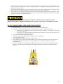
FIRE EXTINGUISHER OPERATION
Fire extinguishers are classed into three categories:
Class A: The agent/powder is suitable for fighting small fires involving wood, paper, cloth, rubber and some plastics.
Class B: The agent/powder is suitable for fighting small fires involving grease, oil, gasoline, kerosene, and other flammable
liquids.
Class C: The agent/powder is suitable for fighting small fires in live electrical equipment.
Your RV is equipped with a category B/C fire extinguisher located near the entrance door. These extinguishers are designed to for
use in small fires that have just started and are small enough to fight safely. It is not designed to fight large fires which are burning
out of control. If the fire is too hot or smoky for you to get within 6 feet, do not try to fight it yourself. Warn everyone, evacuate the
premises, and have someone contact the fire department. Trying to fight a large fire by yourself can result in injury or death.
To fight a fire:
• Remove extinguisher from the mounting bracket.
• Hold the unit firmly with the nozzle facing away from you. Pull out the pin to break the safety seal; you won’t be able to
squeeze the lever until the safety seal is removed.
• Stand back 6 feet (2 meters) from the fire and make sure the fire is not between you and the exit.
• Hold the extinguisher upright and aim nozzle at the base of fire.
• Squeeze and hold the lever to discharge the powder.
• Sweep the spray at the base of the burning material, using quick side-to-side motions. (if the spray scatters the fire move
back).
• Move slowly towards the fire as the extinguisher spray pushes the fire back. Maintain a (six) 6 foot distance between you
and the front of the fire at all times.
• Completely discharge the contents of the extinguisher and make sure the fire is completely out. Flashbacks are common
with fires.
• For kitchen fires on a kitchen stove, turn off the stove immediately if possible; otherwise turn it off as soon as it is safe.
• If you suspect a fire had an electric origin, shut off electric power, if possible, without eliminating your escape route. Do
not touch electrical wires or appliances.
• After you have completely discharged your extinguisher, leave the RV and close the doors behind you.
• Do not reconnect the RV to an electrical power source or use the RV until a qualified inspector has verified the vehicle is
safe to use.
See fire extinguisher manual for additional information regarding your specific fire extinguisher.
DRIVING SAFETY
Driving a tow vehicle while pulling a trailer is substantially different from driving a passenger car in that one must always be
mindful of the overall combined weight and length of the vehicles. The following tips will assist you in safe operation of the
combination vehicle.
•
•
•
•
It is recommended you use a large parking lot as a practice area to become familiar with the turning and stopping
characteristics of your tow vehicle and trailer.
Always apply turn signals in advance prior to making a turn or changing lanes. Start out slowly, swinging wide at the
turns, while constantly monitoring of all sides of the RV. Turns should be taken at slow speeds. Remember that the trailer
wheels do not directly follow the path of your tow vehicle’s wheels. The trailer will follow a path closer to the inside of a
turn than the tow vehicle.
Avoid abrupt starting, stopping, or turning of the RV as one may potentially lose control in those situations; especially
when driving in reduced traction situations such as in rainy, icy, or snowy conditions.
Remember that your stopping distance will be substantially lengthened due to weight and length of the vehicle. Do not
“tailgate”, look ahead and anticipate slowing or stopped traffic.
21
•
•
•
•
•
•
•
•
•
Be cautious when passing or being passed by large vehicles such as trucks or buses, as air turbulence can cause swaying of
the trailer. Do not overcompensate in your steering when you feel the swaying of the trailer.
Only drive at speeds comfortable to you and appropriate for the weather, road conditions, and road grade. Do not exceed
posted speed limits for combination vehicles.
Avoid getting close to a dirt shoulder of the highway as it may not support the weight of your vehicle.
Always check posted heights of bridges and other overhead obstacles. Remember that posted clearances may not be
accurate due to repaving of the roadway or packed snow, etc.
If the trailer begins to move side-to-side or “fishtail”, do not panic and do not jam on the brakes; immediately decelerate,
steering as little as possible to maintain control, and coast to a slower speed. If the “fishtail” reoccurs when speeding up,
pull off to a safe area and inspect your weight distribution. It is possible too little weight has been placed in the area of the
hitch assembly. Review the weight distribution section of this manual and rearrange the weight to meets proper weight
distribution criteria.
Use extreme caution when proceeding downhill. It may be advisable to shift your tow vehicle into a lower gear when
descending hills and mountains to provide additional braking power. Consult your tow vehicle owner’s manual for further
instruction.
Never allow a person or pet to ride in the trailer while trailer is in-motion.
If encountering a flat tire, do not panic and jam on the brakes; reduce speed and coast to the side of the roadway. Park in a
safe location and proceed with a tire replacement.
Back slowly and use a helper when backing the trailer as the helper can see obstacles not visible to the driver.
DRIVING EMERGENCIES
During an accident, tire blowout, or similar emergency, use gentle braking techniques and pull off the traveled roadway to a safe
location. Set the parking brake, turn on the hazard flashers and if along the roadway, display flares or hazard warning triangles.
Typical placement of flares or reflective triangles is 10’, 100’, and 200’ from the rear of vehicle when on a divided highway or oneway road. A road with traffic traveling in both directions require placement of the flares or triangles at 10’, 100’, and 200’ at the
front of vehicle in addition to same placement at rear of vehicle. Hilly, curvy roads require placement of warning in locations in
which oncoming traffic has adequate advance warnings. Please refer to your state’s driver manual for further clarification of
warning devise placement.
REFUELING YOUR TOW VEHICLE
•
•
•
•
•
Stop the vehicle prior to entering the fuel station and turn off the propane gas supply valve at the propane tank. Turn off all
propane appliances, extinguish all open flames, and verify all pilot lights are off.
Do not smoke cigarettes, cigars, or pipes in any area around the fuel fill station.
Use caution when entering a fuel filling station. Certain stations may not have adequate height or length clearances for
your tow vehicle and trailer.
Be careful to avoid collision with the posts which typically surround the fuel island.
Verify the back corner of the trailer has cleared all obstacles at the fuel pump area prior to turning sharply. Failure to heed
this warning may cause damage to the fuel pump and the trailer.
Turn off the propane gas supply valve at the propane tank. Turn off all propane appliances, extinguish
all open flames, and verify all pilot lights are off. Do not smoke in the area of a fuel pump. Failure to
extinguish all flames and potential spark sources prior to refueling of gasoline, diesel, or propane may
result in serious injury or death.
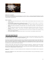
CONDENSATION AND HUMIDITY
The smaller interior volume and sealed construction of your RV means that you must manage the interior humidity levels.
Uncontrolled humidity or moisture generated by bathing, cooking, and even normal breathing can dramatically increase the interior
humidity levels to the point where condensation appears on interior surfaces of the RV. Some studies suggest two occupants can
generate more than a gallon of moisture daily from normal activities. Extreme situations may result in condensation or water
dripping from the ceiling and other interior surfaces. Following the tips below will greatly assist in reducing excessive
condensation to the ideal levels of 35% humidity typically required to prevent condensation on the windows.
1.
2.
3.
Use roof vent or range hood vent during shower use or cooking.
Do not hang wet clothes inside the RV to dry.
Use of roof air conditioner will assist in removing excessive humidity.
22
4.
5.
6.
7.
8.
9.
10.
11.
Allow air to circulate inside the RV. For example, open doors to wardrobe to allow air circulation to the exterior wall.
Open a roof vent or window if the exterior air is less humid than the interior air.
Avoid drastic and abrupt changes in furnace thermostat settings.
Use the least amount of water possible when cleaning the interior of the RV.
Maintain exterior sealants.
Open a vent or window slightly when storing the RV.
Immediately clean and dry all water spills inside the RV.
Use a portable dehumidifier.
Failure to control excessive humidity can result in damage to the RV which may not be covered by the warranty terms. It is
recommended the humidity levels be monitored with a basic hygrometer available at you local building supply store or department
store.
NOTE: Your RV is NOT intended for use as a permanent or long term dwelling. Damage or premature
deterioration of the RV due to long term occupancy may be considered misuse or abuse under the terms of the
limited warranty and may be subject to reduction of warranty coverage or denial of warranty coverage.
MOLD AND MILDEW
Molds are microscopic organisms that occur naturally in virtually every environment both indoors and out.
Indoors, mold growth is undesirable due to the possibly that mold can break down materials such as fabric,
wood and similar products, and because some individuals experience allergic reactions to certain types of
mold.
Mold growth conditions
Mold prefers high humidity conditions in temperatures between 100 degrees and 40 degrees Fahrenheit. Management of humidity
and temperature levels will reduce mold growth.
Methods of reducing mold growth
Mold growth may be reduced by performing the suggested procedures listed in the Condensation and Humidity control section of
this manual. Additionally, immediate clean up of water spill, maintaining a clean environment, reduction of humidity, use of air
conditioner, use of mold killing cleaner on safe surfaces, and wiping down the damp walls of shower after use, will aid in reducing
the growth or spread of mold.
Note: Conditions caused by mold growth are excluded from coverage under the terms of the EverGreen RV’s Limited Warranty.
Please take necessary actions to contain and control the spread of mold.
CHEMICAL SENSITIVITY
When first using you new RV or after periods of storage, you may detect a strong odor when entering the RV. Not unlike your
home, your RV is manufactured using many common building products such as carpet, plywood, upholstery, etc which may contain
chemicals used within the process of manufacturing that particular component. Your RV is tightly constructed which significantly
reduces exchange of outside air; therefore, when new, or when exposed to elevated humidity or temperatures, these products may
“off-gas” quantities of chemicals such as formaldehyde. The off-gassing may cause temporary irritation of the eyes nose and throat.
Young children, elderly persons, and those individuals with a history of respiratory problems, asthma, or allergies may be more
prone to experience discomfort from the off-gassing.
Chemical off-gassing is not a defect and is not covered under any warranty.
FORMALDEHYDE
Most of the interest regarding chemical off gassing involves formaldehyde. Formaldehyde is an ingredient in many
products such as wood paneling, carpet, and other consumer products. While other products in your RV such as carpet
and upholstery may contain formaldehyde, EverGreen RV has carefully selected materials with reduced formaldehyde
emission levels.
23
Smoking inside the RV is not recommended as tobacco smoke releases formaldehyde and other toxic chemicals.
VENTILATING YOUR RV
Ventilating your RV will substantially reduce any build-up of chemicals such as formaldehyde. It is recommended to fully ventilate
the RV during periods of high temperatures/ high humidity and when first using the new RV. The RV may be ventilated by opening
window(s) in conjunction with a roof vent or fan.
WHEELS AND TIRES
Properly maintained tires will improve your trailer’s handling, and stopping capabilities as well as enhancing tire life. This
maintenance section will provide important instruction regarding proper tire/wheel care and maintenance.
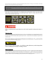
TIRES
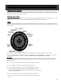
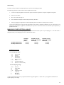
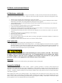
Federal law mandates tire manufacturers to place standardized information on the sidewalls of all tires. This uniform information as
depicted in the example below identifies and describes the characteristics of the tire while providing tire identification in the event
of a safety recall.
Code identifier based upon the generic example above. This example does not reflect the required tires for your trailer.
P – The “P” indicates the tire is for passenger vehicles. Passenger tires are not recommended for use on trailers as the capacity
ratings are not identified on the tire sidewall. Note an “ST” indicates the tire is designed for use on a trailer.
Speed Rating
Tires with a ST designation are speed restricted to 65mph under normal inflation and load conditions. Tires with a LT designation are
speed restricted to 75mph under normal inflation and load conditions. Do not exceed these speed ratings regardless of the posted
maximum speed limit
215 – The “215” reflects the width in millimeters of the tire from sidewall to sidewall.
65 - The “65” reflects the aspect ratio or the tire’s ratio of height to width.
R – The “R” indicates the example tire is a tire constructed of radial ply construction.
15- The “15” reflects the rim diameter. In this case the rim diameter is 15 inches.
Note that rim diameter and wheel diameter must be matched exactly. Do not install a
Tire on a rim of a different size.
95- The “95” reflects the tire load index or maximum weight capacity of each tire.
H- The “H” reflects the speed rating of the tire. Note this rating may not be listed on all
tires.
24
U.S. DOT Tire Identification Number – This number indicates the tire meets all federal standards.
Example of MC3TXRTV0806:
MC – The “MC” reflects the Manufacturer Plant Code.
3T – The “3T” reflects the Government Size and Ply Code.
XRTV – The “XRTV” reflects Manufacturer Construction Code.
0806 – The “0806 is the tire build date. 0806 = eighth week of 2006
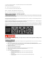
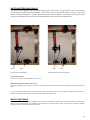
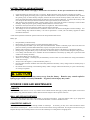
WHEEL LUG NUT TORQUE – Critically Important!
Proper and consistent lug nut torque is essential to safe operation of the trailer. Wheels on trailers are different from wheel on autos
in that trailer wheels are subject to high side load stresses when the trailer makes a turn. These types of side load may flex the wheel
and cause gradual loosing of the lug nuts.
The lug nuts have been checked prior to leaving the manufacturing facility, however “wearing in” of the wheel during initial travel
causes potential loosening of the lug nuts.
The lug nuts must be checked prior to every trip, and every 50 miles for the first 500 miles of use. The proper lug nut
torque for a steel wheel or aluminum wheel (with steel insert) is 115 ft. /lb.
Always use an accurate torque wrench to inspect or tighten lug nuts. Proper torque can only be achieved with use of a calibrated
torque wrench and socket using the tightening sequence depicted below. Refer to your torque wrench operator guide for calibration
information for your specific torque wrench. Always use a torque wrench, do not use any wrench or ratchet other than a torque
wrench.
Over-tightening or under-tightening of the lug nuts may result in wheel separation causing serious
injury or death.
CHANGING A SPARE TIRE
1.
If changing a tire by roadside, place reflective triangles or flares at appropriate distances from your vehicle as a warning to
other motorists.
2. Place a chock or block behind and in front of the wheels on opposite side of the wheel requiring replacement.
3. Place a jack at appropriate position under main frame rail. In most trailers the jack should be placed directly under the
main frame rail adjacent to the wheel requiring replacement.
4. Slightly loosen the lug nuts.
5. Raise the trailer until the tire clears the ground.
6. Remove the lug nuts and wheel/tire assembly.
7. Verify your spare tire/ wheel is of the exact type and specifications as the original tire/wheel.
8. Install spare tire and tighten lug nuts until wheel is tight against the hub.
9. Lower the trailer.
10. Follow a three stage lug nut torque process.
1. Torque the lug nuts to 30 ft./lb. using a torque wrench and following the lug nut
torque pattern prescribed above.
2. Torque the lug nuts to 75 ft./lb. using a torque wrench and following the lug nut
torque pattern.
3. Torque the lug nuts to a final 115 ft./lb. using a torque wrench and following the lug
nut torque pattern.
25
11. Recheck the torque after 10, 25, 50, and 200 miles.
It is recommended that you utilize a tire service center to replace wheels as improper techniques or
equipment may result in serious injury or death. Never use the stabilizer jack as a support of lifting
jack for the purpose or wheel replacement.
Use of damaged or incompatible wheel/tire assemblies may result in wheel/tire separation causing a
potentially hazardous situation resulting in serious injury or death.
REPLACEMENT WHEEL REQUIREMENT
Your original wheel/tire assembly and hub assemblies were carefully selected for compatibility to the axle assembly as well as
meeting load range and safety specifications. It is extremely critical that any replacement wheel/tire or hub meet the following
original specifications. Please verify the specifications prior to installation of the wheel/tire assembly. Do no install any hub or
tire/wheel assembly if inconsistent with the original specifications.
•
•
•
•
•
•
•
•
•
Proper size, type, and load range of tire.
Stud length and diameter.
Number and placement of studs.
Diameter of the hub mounting surface.
Center hole diameter of the wheel.
Wheel lug nut shape and size. (including recessed cone angle)
Rated capacity of the wheel. Verify the wheel meets or exceeds the load rating requirements of the tire and trailer.
Wheel offset. This is the distance of the center line of tire to hub face of axle. Failure to match offset may reduce stability
of the trailer and may cause contact of the wheel/tire assembly with other trailer components.
Other aftermarket wheel accessories that could affect attachment and seating of the wheel to hub surface.
Do not apply paint, anti-seize compound, anti-rust compound, or similar material to the axle hub
surface or wheel assembly as these materials will prevent the required metal-to-metal contact between
the wheel and hub surface. Use of these materials may cause loosening of the lug nuts causing
separation of the wheel from the RV resulting in serious injury or death.
NOTICE
Do not mix bias ply tires with radial tires as the handling characteristics of the trailer may be
negatively affected.
TIRE INFLATION
The tire sidewall will specify the maximum inflation pressures; however you should adhere to the recommended inflation pressures
as defined on the certification label at the left front exterior of your trailer. Your particular trailer certification label may specify a
tire pressure lower than the maximum inflation pressure listed on the tire. Always follow the recommended tire pressure on the
certification label.
Keep a tire pressure gauge in your vehicle and check tire pressure prior to every trip when the tire is “cold”. The term “cold” does
not refer to ambient temperature but rather to a tire that has not been driven on for at least three hours. Tire pressures increase when
in use; therefore the tires must be checked when cold.
26
Keep tires properly inflated at all times. Over-inflation or under-inflation may result in abrupt failure
of the tire resulting in personal injury or damage to the RV.
TIRE TREAD
The tire tread provides the gripping action and traction necessary to prevent your trailer from slipping or sliding on the roadway.
Please check with your state regulatory agency as minimum tread depth regulations may vary from state to state; however most tire
manufacturers will suggest replacement prior to tread depth reaching 1/16 of an inch. Many tires have built in tread wear indicators
that let you know when it is time to replace tires. The tread wear indicators are raised sections spaced intermittently in the bottom
of the tread grooves. When the indicator appears “even” with the tread it is time to replace the tires.
TIRE REPAIR
The proper repair of a punctured tire involves installation of a plug for the hole in addition to a patch inside the tire. Small
punctures in the tread can typically be repaired; however punctures in the sidewall should not be repaired, and instead the tire
should be replaced.
TIRE BALANCE
To reduce vibration of the vehicle during travel, the tires must be properly balanced by a qualified tire service center. The service
center will balance the wheel/tire assembly by positioning small weights on the wheel to counterbalance the heavy or light spots on
the wheel. A properly balanced wheel assembly will maximize the tire life.
WHEEL ALIGNMENT
Your wheels and axles leave the factory in an aligned position; however normal road use and impacts from roadway obstacles may
alter the original alignments. A wheel alignment will adjust or properly position the wheels/tires with the vehicle’s frame, thereby
increase the life of the tire. These types of adjustments require specialized measuring equipment and must only be perform by a
qualified technician.
Note: Wheel alignments are considered a maintenance item and are not covered under any warranty.
Tire Tips
•
Maintain proper tire air pressure at all times. Check tires in a “cold” position or position in which the vehicle has not
been driven for at least three hours.
•
Avoid roadway objects such as debris and potholes.
•
Do not drive over curbs or similar abrupt elevation changes.
•
Remove foreign objects from the tire tread.
•
Always use valve caps on the tire valves.
•
Do not overload the RV.
•
Inspect tires and take immediate action if uneven wear, cuts, bulges in the sidewall or other such abnormalities become
apparent.
•
Check tire pressure prior to ever trip.
•
Check tire pressures frequently when driving in hot weather. Do not let air out of hot tires as they will return to proper
pressure as they cool.
27
HITCH SELECTION
There are a variety of hitch configurations, types and brands available. Please provide your tow requirement information to a
qualified hitch installer and follow their recommendation as to appropriate hitch equipment for your specific use. It is important
the hitch equipment also be fully compatible with the tow vehicle. Be certain the hitch and tow vehicle weight and tow ratings are
sufficient for safe towing of your trailer. It is critically important the ball hitch size matches the coupler size. A sway control hitch
is recommended. Please consult with your local towing expert as to which anti-sway devise may be recommended for your
application.
Failure to properly attach and secure a trailer to the tow vehicle can result in serious injury or death.
Use of a tow vehicle with insufficient towing capacity can result in loss of control causing injury or
death.
HITCHING A TRAVEL TRAILER
1.
2.
3.
4.
5.
6.
7.
8.
9.
10.
11.
12.
13.
14.
15.
16.
17.
18.
Raise the tongue of the trailer upward until the hitch coupler is high enough to clear the tow vehicle hitch.
Back the tow vehicle to the trailer until the hitch ball is directly under the trailer coupler.
Set the parking brakes, raise the locking latch on the coupler and lower the hitch down onto the ball.
Move the locking latch to the down to latch it onto the hitch ball.
Engage the locking clip on the coupler latch.
Insert a locking pin through the locking clip.
As a test to verify proper coupling, lower the jack to verify the tow vehicle is raised when the jack is extended.
Connect the power cord to the tow vehicle.
Connect the breakaway switch making certain the breakaway cable is not attached to any removable portion of the tow
vehicle hitch assembly.
Connect the safety chains to the frame of tow vehicle in the portion designed for safety chain attachment. Cross chains
underneath hitch with coupler adequate slack to permit turning and to hold tongue up if the trailer should become
detached.
Fully raise jack all the way upward.
Check all lights (including turn and brake light) on the trailer and tow vehicle.
Check and adjust mirrors of tow vehicle.
Verify area is free of objects under and around the trailer and tow vehicle.
Check tire pressure.
Check lug nut torque (see lug nut torque section ---- for further instruction).
Pull forward and with the hand control, check operation of the trailer brakes. Please refer to your brake control manual for
adjustment operation of brake control.
Check the level of tow vehicle and trailer. A level arrangement will greatly enhance the towing experience. A hitch that is
too high will cause the rear of trailer to contact the roadway and a hitch that is too low can cause the front of trailer to
contact the roadway.
Safety chains must be used when towing. Improper attachment of the safety chains can result in loss
of control of both trailer and tow vehicle resulting in serious injury or death.
NOTICE
The breakaway switch is only to be used in emergencies. Do not use this switch as a parking brake.
The breakaway switch will only operate when powered by 12-volt battery or power supply.
28
WEIGHT SECTION
WEIGHT TERM GLOSSARY
Gross Vehicle Weight Rating (GVWR): is the maximum allowable weight of the trailer when fully loaded including all personal
possession, propane gas, water, and the actual trailer.
Unloaded Vehicle Weight (UVW): is the weight of the trailer in the unloaded or empty condition.
Cargo Carrying Capacity (CCC): Is equal to the GVWR minus each of the following: UVW, full fresh water weight including
the water heater capacity, and full propane.
Gross Axle Weight Rating (GAWR): Is the maximum weight carrying capacity of a single axle as measured at the tire–ground
interface.
Gross Vehicle Weight (GVW): Is the weight of the coach with all items and supplies that are loaded into the vehicle at any given
time.
Gross Combined Weight Rating (GCWR): The maximum allowable combined weight of the tow vehicle and trailer. This rating
is established by the tow vehicle manufacturer.
PROCEDURES FOR WEIGHING YOUR TRAILER
Locate a scale large enough to weigh the combined length of your trailer and tow vehicle. These types of scales are generally
available at truck stops and travel centers.
HITCH WEIGHT
Drive the loaded trailer onto scales making certain the trailer hitch (or tongue jack) will be the only contact point with scales after
unhooking from tow vehicle. Unhook and drive the tow vehicle off the scales. Level the trailer and record the hitch weight.
AXLE WEIGHT
Hook up the tow vehicle again and drive forward on the scales until only the trailer axles are on the scale (with hitch past the scale).
Level trailer and record axle weight with tow vehicle attached.
TOTAL WEIGHT OF TRAILER
Place both trailer axles and trailer hitch (or tongue) on the scale, with tow vehicle unhooked, and record the weight.
TOTAL WEIGHT OF TRAILER AND TOW VEHICLE
Place both trailer and tow vehicle on the scale without unhooking. Record weight and verify weight is within specifications of tow
vehicle.
WEIGHT DISTRIBUTION AND LOADING
Proper weight and load distribution is critical to safe towing. It is necessary to maintain a certain percentage of the trailer’s weight
on the tow vehicle. Typically 10% - 14 % of the travel trailer weight is recommended to be placed on the tow vehicle.
Too little or too much weight on the hitch can create extremely dangerous driving conditions and loss
of control resulting in serious injury or death.
Do not under any circumstance exceed the established single or combined trailer or tow vehicle weight
ratings (GVWR, GAWR, GVW, and GCWR).
29
Weight tips
• It is not recommended you travel with full tanks of fresh water. Travel with only enough fresh water for travel purposes
or for load balance.
• Waste (black/grey) tanks should always be emptied prior to travel.
• Refrain from loading heavy items into upper cabinets as this raises the overall center of gravity. Heavy items should be
placed as close to the floor as possible.
• Items placed inside the RV must be secured to prevent movement and damage during travel.
• Do not load items onto the rear bumper.
• Adjust cargo to keep the side-to-side weight distribution as equal as possible.
• Do not strap items to the roof of the RV.
• The amount of cargo will affect the quantity of water and propane you can carry and still remain within the weight
ratings.
• Propane weighs 4.2 pounds per gallon.
• Water weighs 8.3 pounds per gallon.
• Don’t forget to revise your weight calculation to include those items purchased during your trip.
Do not allow any person or pet to ride inside the trailer while trailer is in motion. The trailer is not
intended or designed to carry passengers and is not equipped with seatbelts. Serious injury or death
may result from riding inside the trailer.
LEVELING THE RV
Use the following detail as an outline for leveling the trailer when parking at a campsite. The trailer must be level prior to operation
of slide rooms or appliances. The level should be checked using a two foot carpenter’s level place on the floor of the trailer.
1.
2.
3.
4.
5.
6.
7.
Select a site that is as level as possible.
Move the trailer to the site check side-to-side level by placing the carpenter’s level on the floor in a side-to-side position.
If not level, drive one side of the trailer wheels up onto the blocks such as 2” x 8” wood blocks. Keep adding blocks until
level side-to-side.
When level side-to-side, place wheel chocks at the front and rear of trailer tires to prevent movement.
Disconnect the 12-volt connector, safety chains and break-away cable from the tow vehicle. Release the hitch latch, raise
front jack and drive tow vehicle forward. Note: on soft ground, it may be necessary to place a wood block under the jack.
Check the level by placing the carpenter’s lever front-to-back on the floor of trailer. Raise or lower the front jack to level
the trailer front to back.
Connect electrical power cord, extend the slide-out rooms, and connect the water and sewer hoses.
If equipped with stabilizer jacks, you may now extend the jacks to stabilize the trailer. Extend them only far enough to
contact the ground and no further. Note: the stabilizer jacks are not designed to raise the trailer. These jacks are
designed to stabilize the trailer.
Do not use the stabilizer jacks to raise or level the trailer. Do not use the stabilizer jacks to change a
tire. Damage to the stabilizer jacks and trailer frame can occur which is not covered under any
warranty.
30
ELECTRICAL SYSTEM
The trailer’s electrical system combines a 120-volt (household receptacle voltage) along with the 12-volt system.
120-VOLT SHORE POWER ELECTRICAL SYSTEM
The 120-volt system operates solely from an electrical shore power cord or a generator. The 120-volt system operates the interior
receptacles including appliances such as the roof air conditioner and microwave. These appliances will only function when
connected to an exterior 120-volt power source. The 120-volt system also operates a converter charger inside the trailer. This
converter charge is attached to the interior load center which houses the fuses and breakers for the trailer. The converter/charge
“converts” or changes the 120-volt AC power to 12-volt DC power. This arrangement allows the 12-volt trailer battery to be
charged when the trailer is connected to 120-volt shore power.
120-VOLT ELECTRICAL LOAD CENTER (Breaker Box)
The load center location may vary dependent upon your particular floor plan, however in most cases the load center may be located
at the base of bed, kitchen or dinette. The 120-volt electrical power is routed through the electrical lead center which is equipped
with a 30 amp or 50 amp main electrical breaker and a combination of other 15 amp and 20 amp circuit breakers for the branch
circuitry. Each breaker is labeled with the general location of the area to which it supplies power. The circuit breakers will open (or
trip) when the rated current has been exceeded or the particular circuit has been “short-circuited” (when wires touch each other or a
grounded surface). To reset the breaker, move the lever to the off or down position then up to the on position.
12-VOLT POWER SYSTEM
Your trailer is wired and designed to accommodate one 12-volt deep cycle battery or in some cases, multiple batteries. This battery
provides an electrical reservoir of power for moderate use of the 12-volt items such as the water pump, interior lights, furnace, slideout and other such items. This battery will be charged when connected to 120-volt shore power or by the tow vehicle alternator
when connected to a two vehicle with auxiliary charging capacity.
12-VOLT FUSES
The 12-volt type ATC replaceable blade fuses will be located adjacent to the electrical load center. These fuses will control 12-volt
items and components such as interior lighting, ceiling fans, water pump and other accessories. The fuses will be labeled with the
general area which it controls.
The link connector inside the fuse will separate when the amperage has exceeded the fuse ratings. Always replace a fuse with one
of identical type and amperage. Installation of a fuse with higher amperage rating may result in melting of the circuit wires and
significant risk of fire. It is advisable to keep spare fuses in the trailer in the event the fuses are required during future camping
trips.
12-volt battery tips
• Batteries are not supplied or warranted by EverGreen RV.
• Improper connection of batteries to the trailer can cause significant damage (including fire) to the trailer and its
components.
• Batteries must be installed in a vented protective plastic battery box.
• Deep cycle RV or Marine batteries are recommended. Standard automotive starting batteries will provide limited life in
this type of application.
• Battery life is completely dependent upon use and maintenance of the battery. A typical user may find the battery requires
replacement about every two years. See battery care in the maintenance section.
• Please note one 12-volt battery will provide limited long term power to the trailer. Please plan ahead and manage the
power usage when camping without access to 120-volt shore power to charge the battery. Please see power use section for
further information.
• Low battery power will cause significant issues with operation of microprocessor controlled components such as
refrigerators and furnaces. For example the refrigerator will require at least 10.5 volt for proper operation.
If
experiencing problems with 12-volt components, please first fully charge the battery and again attempt operation of the
component prior to seeking repair of the appliance.
• Battery maintenance is critical. Please see the battery maintenance section.
• Extreme care must be taken when handling, connecting, or servicing batteries.
• Do not operate slide rooms unless connected to shore power or your tow vehicle with engine running.
• Discharged batteries can freeze when left in cold temperatures.
• Remove or disconnect the battery when charging from an external charge source other than the on-board converter/charger
or tow vehicle.
31
•
•
•
Some equipment or accessories in the trailer may draw small amounts of current even when in the off position. It will be
necessary to disconnect the battery or turn the battery disconnect (if so equipped) to the disconnected position when
placing the trailer into storage.
Interior lights inadvertently left in the “on” position are the most common cause of battery drain. If storing the trailer,
please make certain all lights are turned off especially those in the exterior storage compartments.
Many refrigerators are equipped with humidity control switches located inside the main door of the refrigerators. While
effective, this feature can use significant amounts of power. You might consider turning this feature to the off position if
camping in an area without electrical shore power.
Unauthorized modifications to the electrical system may void the electrical system and related
component warranties. Improper modification may result in serious injury, electrocution, or death.
120-VOLT SHORE POWER CORD CONNECTION PROCESS.
Connecting to shore power
1. Turn off the 30 amp or 50 amp main breaker at the trailer’s load center (inside the trailer).
2. Verify proper electrical supply rating prior to connecting the power cord to a campground receptacle.
• 30 amp service is a single phase 120-volt receptacle with three connectors - one power wire, one ground
wire and one neutral wire.
• 50 amp service is a single phase 220-volt receptacle with 4 connectors- two power wires (each with 120volt) one ground wire and one neutral wire.
3. Turn off the breaker at the campground receptacle.
4. Insert the power cord into the campground receptacle and turn on the breaker
at the campground receptacle.
5. Turn on the breaker at the trailer load center (inside the trailer).
6. Insert a polarity tester (such as the one pictured below) into a receptacle inside the trailer. Verify proper polarity by
following the instruction listed on the tester. These polarity testers are available at minimal cost from home
improvement stores.
7. Promptly turn off the trailer load center breaker and unplug the power cord if the polarity tester indicates improper
polarity. Contact the campground management and request an immediate inspection of the campground electric
receptacle.
Electrical Polarity tester
32
To disconnect from shore power
1.
2.
3.
4.
Turn off the major appliances such as air conditioner.
Turn off main breakers off at trailers load center (inside the trailer).
Turn off breaker at campground receptacle.
Disconnect power cord, coil and store.
Never replace fuses or breakers with those of a higher amperage rating of different type than
originally specified. Installing breakers or fuses of higher amperage may cause overheating, wire
failure and fire causing serious injury or death.
120-volt electrical troubleshooting and tips.
•
•
•
•
•
Except in extreme emergencies, do not use power cord adapters to connect from 15 amps to 30 amps or 30 amps to 50
amps. Use of these adapters can reduce the total electrical current available for use in the RV causing a low power
situation resulting in damage to electrical components. Additionally, high amperage draw through these adapters may
result in failure of the adapter thereby causing a fire.
Check the reset button on the GFCI receptacle if any receptacle in the trailer is not functioning. Frequently, just
resetting this button on the GFCI will restore power to the non-functioning receptacle.
Only connected the power to a grounded receptacle.
If a 120-volt breaker trips or blows, you may have too many appliances connected to that one circuit. Try moving
appliances such as heaters, hair dryers, and toasters to another electrical circuit.
Do not use extension cord between your trailer’s power cord and an electrical supply as the additional cord length
may reduce voltage to the trailer causing damage to the electrical components within the trailer.
NOTICE
Use of power cord adapters and power cord extensions may cause damage to the electrical components
of the trailer. Damage caused by such use of adapters or extensions is not covered under any
warranty.
GROUND FAULT CIRCUIT INTERRUPTER (GFCI)
The kitchen, bath, and exterior electrical receptacles are protected with a Ground Fault Circuit Interrupter (GFCI) receptacle. A
GFCI is a device that disconnects a circuit whenever it detects that the electric current is not balanced between the phase ("hot" or
"live") conductor and the neutral conductor. Such an imbalance is sometimes caused by current leakage through the body of a
person who is grounded and accidentally touching the energized part of the circuit. GFCI is designed to break the flow of current to
the protected outlet(s). The GFCI will not protect against short circuits or overloads.
Even with GFCI protections, persons with severe heart or similar health problems may still be
seriously affected by an electrical shock. The GFCI is not a replacement for good electrical safety. It
DOES NOT protect against simultaneous contact against neutral and hot wires.
33
GFCI Testing
The GFCI circuitry should be tested upon purchase of your RV and monthly thereafter.
The following procedure is used to test the GFCI receptacle and circuitry.
1.
Connect a test light or appliance such as a hair dryer to the GFCI receptacle to verify the receptacle is energized.
2.
Press the “test” button.
3.
The “reset” button will pop out.
4.
Power should be interrupted to other outlets protected by the GFCI.
5.
Verify by plugging in a light at these outlets and pushing in the reset button to confirm power is restored.
If the “reset” button does not pop out after pressing the “test” button or the GFCI continues to trip, or if the power is not
interrupted to the test light or appliance, immediately turn off power at load center and have the electrical system inspected by a
qualified electrician.
MANAGING YOUR ELECTRICAL USAGE
Your recreational vehicle is carefully designed with a sophisticated electrical system for your camping use. The chart below is
designed to assist you in managing power use of the electrical system.
30-Amp 120-V Service
50-Amp 120-V Service
Available
120-volt
power
25 Amp
42 Amp
Available 12-volt
power with 45 Amp
Converter
45-Amp
45-Amp
Available 12-volt
power with 55 Amp
Converter
55-Amp
55-Amp
Common Power Usage
12-Volt amperage usage*
4- 8
4- 6
3- 4
1
1- 2
3- 14
3- 5
1- 2
Water pump
Furnace
Refrigerator
Water heater
Range hood fan
Radio
TV Antenna Booster
Roof A/C control circuitry
120-Volt amperage usage*
12-16
12
10
7-13
8
8
4
Roof A/C
Water heater
Toaster
Microwave oven
Coffee Pot
Hair dryer
Refrigerator
* Note the represented usage is only a general estimation of typical appliances. Please refer to your appliance information for
specific amperage use ratings.
34
PROPANE SYSTEM
Propane gas (also known as LPG or Liquefied Petroleum Gas) is a clean burning dependable gas used for operation of certain
appliances such as the stove top, oven, refrigerator, water heater, and furnace. Propane contains an added distinctive odorant similar
to rotten egg smell. Immediately take precautionary measures if encountering this distinctive odor. The Propane system includes
the pressurized propane cylinder(s) (also known as bottles or tanks), regulators to meter the gas pressure, flexible connector hoses,
iron manifold supply line and the copper connector lines to the appliance. The LP cylinders contain liquid under high pressure,
which vaporizes into a gas and passes though the regulator which reduces the pressure to a level appropriate for the appliances.
See Propane safety section for further cautionary information.
Propane gas is highly volatile and extremely flammable. Do not use matches or any flame to test for
leaks. Only use approved gas testing leak solution to check for leaks as unapproved solution may
cause damage to copper tubing and brass fittings. Do not attempt to adjust the propane regulator.
Only qualified trained personnel should adjust or perform maintenance and repair to the propane gas
system. Improper handling, repair, or maintenance may cause serious injury or death.
•
If at any time you smell Propane;
1. Immediately extinguish all smoking materials, open flames, and pilot lights.
2. Do not touch any electrical switches or components as arcing may occur.
3. Shut off the gas supply at the propane tank by turning the valve clockwise.
4. Open all entry doors and windows.
5. Do not use the power range hood or power roof vents.
6. Clear the area until the propane odor is no longer apparent.
9. Have the propane systems checked prior to again using the propane system.
REGULATORS
Most propane regulators are of a two stage design in which two regulators are contained within the same body. The first regulator
reduces the pressure to approximately 10 to 13 PSI with the second regulator reducing the pressure to about 11 inches of water
column measurement. This arrangement results in a safer and efficient system with consistent pressure to the appliance.
Automatic switchover regulator (if equipped) is a regulator which senses the gas level and switches to the full propane cylinders
tank when the first cylinder is empty on a two bottle system. The arrow on the regulator will point to the tank which is in use. On
standard regulators without auto switchover, it will be necessary to manually turn the arrow on the regulator toward the full cylinder
bottle when the red flag appears in the inspection glass of the regulator. The red flag indicate the cylinder bottle is empty.
Consumption of propane gas is strictly dependent upon use and frequency of appliances. The propane will be used much more
quickly with extensive use of the stove and furnace. It is recommended during cold weather, to keep one propane cylinder bottle
full at all times.
Do not fill a propane bottle unless fully trained and qualified to perform the procedure. Improper
propane handling may result in serious injury or death.
FILLING PROPANE CYLINDERS
Your RV is equipped with a type I cylinder connection making them easy to connect and disconnect. The type I connection system
uses the excess flow pigtail hose which is distinguished by the large green swivel nut. The green swivel nut attaches to the cylinder
valve with right hand thread. Tighten the swivel nut by hand. Do not use a wrench or pliers to tighten this green swivel nut. The
excess flow feature is a safety feature that limits the flow of gas unless the connection is tight.
Procedure for filling Propane cylinders equipped with an OPD (Overfill Protection Device) valve
1.
2.
3.
Only permit qualified trained personnel to fill the propane cylinders.
Stop the vehicle prior to entering the fuel station and turn off the propane gas supply valve at the propane
cylinders. Turn off all propane appliances, extinguish all open flames, and verify all pilot lights are off.
Shut off tow vehicle and extinguish all pilot lights and turn off all appliances prior to filling tanks.
35
4.
5.
6.
7.
8.
9.
10.
Extinguish all cigarettes, cigars, or pipes.
Ensure that the valve on the cylinder is in the closed position.
Attach the fill hose to the cylinder tank outlet.
Turn on the propane supply source.
Open the bleeder valve screw on the LP tank by 10 percent.
Slowly open the cylinder bottle hand wheel valve approximately one-quarter turn.
As the cylinder begins to fill, the hand wheel valve may be opened further. Opening one full turn is all that
is necessary to fill the tank.
11. When the bleeder valve begins to spit liquid, shut off the LP fill source, close the bleeder valve screw on the
cylinder then close the valve.
12. Do not relight the appliances until you have driven at least ! mile from the fill station.
Propane cylinders, regardless of size, shall never be filled to more than 80% of capacity. Never
attempt to connect or use natural gas to this system. Failure to follow these rules may result in a
failure or event causing significant injury or death.
PLUMBING SYSTEMS
The plumbing system in your trailer is typically categorized into three primary sub-systems: Fresh water, Gray water, and Black
water.
Fresh or Potable water is stored in the fresh water tank or is directly introduced into the plumbing system by way of the
city water fill located on the exterior of the trailer.
Gray water system consists of the waste water from the sinks and tub/shower.
Black water system consists of the waste water from the toilet.
Road vibrations, and shock as well as excessive water pressure from city water sources are the main physical causes of water system
damage. It is important to frequently inspect all plumbing fittings and joints for water seepage. Many times a minor leak is easily
corrected merely by hand tightening the plastic fittings. Do not over tighten the fittings.
NOTICE
Water leakage from plumbing joints may result in considerable damage if left unchecked. It is the
owner’s responsibility to promptly take necessary action to lessen damage due to water leakage.
FRESH WATER AND WATER PUMP SYSTEM
The fresh water tank may be filled from the exterior water fill by inserting an open-end garden hose into the city water fill then
filling until the monitor panel indicates the tank is full. Only open the valve on your garden hose faucet about 50% when filling the
fresh water tank. do not fill the fresh water tank at full volume/pressure of your garden hose as full volume may not allow the tank
to vent quickly enough –thereby causing unnecessary strain on the tank.
Water pump operation
1. Confirm water is present in the fresh water tank.
You may visually check the tank or use the tank monitor panel to confirm water level.
2. Open hot and cold kitchen, bath, and shower faucets.
3. Open the water heater bypass valve to allow water heater to fill.
4. Turn on the water pump.
5. Close each faucet after the water is flowing steadily.
6. The water pump will stop running when the water lines are fully pressurized.
7. The pump is a demand only pump which means that when the pump switch is in the “on” position the pump will run
when using water.
Note: If the pump cycles on/off while not using water, you may require minor adjustment of the water pump pressure switch or
have a minor water leak in the plumbing system. Seek service advice if the pump continues to cycle when not using water.
36
SANITIZING THE FRESH WATER SYSTEM
Keeping the fresh water system free of contaminates is critical in proper use of the fresh or potable water system. To sanitize and
reduce growth of algae and similar contaminants, you may sanitize the fresh water system using the following procedure:
1.
2.
3.
4.
5.
6.
7.
8.
Drain the fresh water tank.
Prepare a chlorine solution of using one gallon of water and " cup of liquid bleach for every 15 gallons of tank capacity.
Close all drains and faucets.
Pour the solution into the fresh water tank by way of the exterior tank fill.
Turn on pump and open each faucet until the water flows freely and a distinct odor of bleach is present. Close the faucets.
Allow the system to sit undisturbed for approximately 3 – 4 hours.
Drain the system by opening all faucets and drains while running the water pump.
Continue filling the entire water system with clean water and run water through all facets until the bleach odor is no longer
present.
9. Fill the water system one more time followed by a final draining of the tanks.
10. Replace the water filter if so equipped.
11. The system is now ready for normal use.
Connection to city water
You may bypass the fresh water tank and connect a garden hose directly to the exterior water fill which is threaded to accept a
garden hose. This method will bypass the fresh water tank and pump and will use the garden hose pressure to supply water to
faucets. Typically this is the preferred water use method when in an improved campground.
Water heater
The water heater in your trailer is fueled by propane with a 12-volt electronic ignition switch. Your water heater may also be
equipped with a 120-volt electric heater element for use when connect to 120-volt shore power.
NOTICE
The water heater must be completely filled with water prior to turning on the propane or the electric
heater element. Even momentary operation of the electric heater without submersion in water will
damage or burn out the 120-volt heater element. Element failure is not covered under any warranty
terms.
WATER HEATER PRESSURE RELIEF VALVE
Your water heater is equipped with a pressure relieve valve which is located behind the exterior access door. This valve will open
when excess pressure or temperature is reached. Due to the smaller size of the water heater tank, slight dripping of the pressure
valve is normal due to water expansion when heating the water. One can minimize the dripping by creating or replenishing an air
pocket at the top of the tank using the following the procedure list below.
1.
2.
3.
4.
Turn off the water heater
Turn off the water supply (if connected to city water) otherwise, turn off the water pump.
Open the Pressure Relief Valve by lifting up on the lever at top of relief valve. Relief valve is to remain open until
water stops flowing. Caution: protect yourself from the hot water following from the valve as scalds and burn could
occur.
Allow the valve to snap closed and turn on water pump or water supply and allow the system to refill.
This procedure will allow formation of a small air pocket at the top of tank. This air pocket will assist in absorbing the expansion of
water during future uses of the water heater.
The water heater must be drained when placed in storage or when subjected to freezing conditions. A water heater failure due to
freezing is considered misuse or abuse and is not covered under any warranty.
Please see the water heater owner’s manual supplied with the RV for further operating, use, and care instruction.
37
WATER HEATER BYPASS VALVE
Your trailer may be equipped with a water heater bypass valve system. This is a system of three valves located at rear
of water heater accessible from inside the trailer. There will be a valve on the top (hot output) water line, a valve at the
bottom (cold inlet) in addition to one valve located between the hot and cold lines. The purpose of this bypass system
is the allow winterization of the water system without filling the entire water heater with antifreeze.
Closed
Open
Valve position for normal use.
Open
Closed
Valve position for water heater bypass
Normal valve position
Center valve is closed with top and bottom valve open
Winterization (bypass) position of the valves:
Close top and bottom valve and open center valve. This position connects the hot and cold lines together and bypasses the water
heater.
Note: always check the positioning of the water heater bypass valves if at any time if the water heater is running but no hot water is
available. The problem may be easily solved with proper placement of the valves.
WATER LINE DRAINS
The fresh water system is typically equipped with at least two water drains which extend downward below the chassis frame.
Removal of the threaded drain caps will allow water to drain out of the fresh water system. It will still be necessary to add RV
antifreeze in order to fully winterize the water system.
38
WINTERIZATION OF PLUMBING SYSTEM
It will be necessary to winterize the water system of your RV when storing or using the trailer in subfreezing weather. Failure to
properly drain and winterize the water system will result in freeze damage this is not covered under any warranty.
1.
2.
3.
Park the recreational vehicle on a level surface.
Completely drain the black and grey waste water tanks.
Turn the water pump off, and then open all faucets, low-point drains, water heater exterior drain plug, and fresh water tank
drain.
4. When completely drained, close the faucets, and drains.
5. Remove water filter (if so equipped)
6. Position the water heater bypass valves to closed top and bottom with the center valve open. Note, if properly drained of
water, it is not necessary to fill the water heater with RV antifreeze. Antifreeze (and water) is prevented from entering the
water heater when valves are in the winterization mode.
7. Remove the inlet line to the water pump and connect a temporary hose from the inlet side of pump to a container of RV
antifreeze.
8. Run the water pump until the RV antifreeze flows freely and is visible on both the cold and hot portions of each faucet.
9. Flush the toilet multiple times until the antifreeze is visible.
10. Add several cups of RV antifreeze to the kitchen sink drains, the bath sink drain and the tub/shower drain.
11. Reinstall the drain plug on exterior of water heater.
12. Remove the temporary hose at water pump and reconnect original water line.
Only use non-toxic RV anti-freeze. DO NOT use automotive antifreeze to winterize your RV as
serious injury or death may occur from ingestion of toxic antifreeze.
Be sure to discuss winterization techniques and needs with your dealer who is familiar with your local climate.
De - Winterization of the fresh water system
The following procedures are recommended when removing the RV anti-freeze from the water system in preparation of vehicle use.
1. Fill water tank with fresh water.
2. Turn on water pump.
3. Run the hot and cold side of each faucet until the water is no longer tinted by the RV antifreeze.
4. Flush toilet until water is clear.
5. Drain the fresh water tank.
6. Perform the water system sanitization as prescribed in this manual.
7. Install a new water filter (if so equipped).
8. Upon completion of the sanitization process, change the water heater bypass valves to the normal position (top and bottom
valves open and center closed).
Reminder: do not turn on the water heater until the water heater is completely filled with water.
WASTE WATER TANKS
The shower and sink water is discharged into a holding tank which is commonly referred to as a “Gray” water tank. This tank
connects to an exterior valve with a connection for sewer hose.
The toilet waste and water is discharged into a separate holding tank which is also referred to as a “Black” tank. This tank also
connects to an exterior valve adjacent to the “grey” valve.
EMPTYING THE WASTE WATER TANKS
1.
2.
3.
4.
5.
6.
Remove the exterior sewer valve outlet cover by turning it counterclockwise
Attach sewer hose to the valve outlet by placing the hose over the valve and turning it clockwise to latch.
Place the other end into an approved dump station inlet making certain the hose is secured so as to prevent movement
when empting the tank.
Arrange the hose to slope downward from the trailer to the drain.
Open the Black drain valve (the larger valve) by pulling the valve handle away from the trailer.
Open the Gray drain valve (the smaller valve) by pulling the valve handle away from the trailer. Note that on certain
floor plans, a second gray tank is installed. In this case, there will be two gray valves to operate.
39
7.
8.
9.
10.
11.
12.
13.
Allow all tanks to drain completely.
Run fresh water through both tanks to rinse the tanks.
Close all drain valves.
Remove the sewer hose and rinse hose with fresh water.
Secure sewer outlet cover.
Secure sewer hose.
Add odor control chemicals and two or three gallons of water to the Black water tank prior to your next usage as this
will assist in preventing build-up of solids.
Waste tank tips
• Only empty tanks into an approved dumping facility. It is unlawful to empty these tanks into sewer drains or other such
unapproved locations.
• Solid waste build-up inside the black water tank is possible. It is recommend you use adequate amounts of water when
flushing the toilet as this will aid in rinsing out the tank when emptying the tank. Should you have a problem with solids
build- up in the black tank, close the valve, fill the tank about ! -3/4 full then drive around to agitate and loosen the solids.
• Do not dump black tanks until # full. This practice assists in making certain that enough water is in the tank to flush out
the tank waste. If necessary, fill the tank with fresh water to the # level prior to empting the tank.
• Do not introduce items such as paper, gum wrappers, sanitary products, cigarettes, facial tissues, paper towels, and food
scraps to the holding tanks. Note some of these items may state they are flushable; however they are only flushable in
home sewer systems. Addition of these items to the tank will likely cause significant obstructions which will not be
easily removed. Note: removal of foreign objects from holding tanks is not covered under any warranty.
• State and local regulations may prohibit highway travel unless the holding tank outlet is securely capped.
• Keep two garden hoses. One to fill the fresh water tank and one to rinse the sewer hose. Cross contamination between the
hoses may occur causing significant health risks.
• Use only biodegradable toilet tissues formulated for RV sewer systems
• Do not place any item into the tank that can puncture, damage or scratch the tanks.
• Use a deodorizing agent designed for RV use, in your black water tank.
SLIDE-OUT ROOM SYSTEMS
12-volt motors are used to extend and retract the slide-out rooms. It is recommended that the RV be connected to shore power or to
a tow vehicle with engine running when operating the rooms. Reduced battery power will hamper or prevent movement of the slide
room.
Dependent upon specific model, your RV may be equipped with either a hidden slide-out mechanism system or an in-wall slide-out
mechanism. The in-wall system has motors built into the wall with the grooved tracks visible at the top and bottom of the slide-out
exterior end walls. The hidden system will not have exposed grooved tracks at the end walls.
Transit bar for slide room
The hidden slide-out mechanism utilizes removable transit bars which are placed on top of the retracted slide room between the
inside of exterior wall and interior slide-out fascia. Tighten the center bar by hand. Do not over- tighten or use a tool to tighten the
bar. Note that smaller slide rooms will be provided with one transit bar and larger rooms will utilize two bars.
Transit bars are not required for the in-wall slide-out mechanism.
If using an RV with the hidden slide-out mechanism, always install the slide room transit bars prior to
transporting the RV. Extending the room without removing transit bars may result in damage to the
RV or a person. Damage to the RV caused by improper use of the transit bars is not covered under
any warranty.
Manual operation of the slide room
In-Wall slide-out mechanism
The slide-out may be moved manually after disconnecting the wire harness to the control box. Please contact your dealer or
Evergreen RV to obtain information regarding the exact procedure and location of the control box. Dependent upon the model it
may be necessary to fabricate a transit bar for transport of the RV to a service center after the wire harness has been disconnected.
40
Manual operation connection point for hidden slide system
Hidden slide-out mechanism
The room may be manually retracted or extended using a 5/8” wrench or socket. Locate the hexagonal shaft adjacent to the slide
motor which is located inside the RV at base of slide room. Using a 5/8” wrench, turn the shaft clockwise to extend the room and
counterclockwise to retract the room.
Slide out room tips
• Always remove slide room transit bars prior to extension of slide room and install the slide bars after retraction of room
and prior to travel.
• Ensure that batteries, battery terminals, and battery cables are well maintained and in optimal condition. See maintenance
section for further information as to proper maintenance techniques.
• Always level your trailer prior to extending or retracting the slide room. Failure to properly level the trailer may cause
damage to the slide room, mechanism, or structure which is not covered under any warranty. See leveling section for
direction.
• The exterior rubber seals at the slide out are subject to deteriorating or hardening due to exposure to ultra violet (UV) rays
and other atmospheric conditions. These exterior seal should be regularly maintained, inspected, and replaced is
necessary.
• Failed rubber seals remaining in service after deterioration will allow rain and snow to infiltrate the RV potentially causing
damage to the vehicle and contents.
• Do not operate multiple rooms or switches at any one time. Only one room is to be extended or retracted at a time.
CARE AND MAINTENANCE
Please read and adhere to care and maintenance instruction and recommendations located within this manual as well as a literature
and manual supplied by the respective component manufacturers. Failure to perform the recommended inspections and
preventative maintenance may void or limit all or part of warranty coverage.
Performing the recommended maintenance procedures at the prescribed intervals noted in the back at the end of this chapter, will
protect your investment, provide greater visual appeal, and will provide future enjoyment and usage of the RV. Please contact your
dealer or EverGreen RV should you have any questions regarding proper care and maintenance of the RV. Page 60 of this manual
has been provide to record date and type of maintenance performed. Please keep detailed records of the maintenance history as this
information may be required for future warranty information.
Frequency of usage, climate, and storage location will affect the required rate of maintenance. Maintenance of the exterior surfaces
and seals must be performed more frequently in those climates or conditions with substantial temperature changes. For example,
the life of exterior sealants will be lessened if an RV is used or stored in the extreme cold of a Northern climate then transfers to the
extreme heat, sun, and high humidity of a Southern climate.
Always refer to the appliance and component manufacture literature for maintenance and use information relative to that specific
component.
Please refer to the maintenance chart contained within this section for further information as to the prescribed frequency of specific
maintenance procedures.
41
EXTERIOR, CARE AND MAINTENANCE
Descriptions of proper maintenance procedures
EXTERIOR WALL SURFACES
Care of the exterior wall surface in not unlike caring for an automobile. As with your auto, the exterior surface can fade and lose
some of the glossy finish properties over time. Proper care of the exterior surface will greatly extend the life and appearance of the
RV.
•
•
•
•
•
•
•
•
•
•
•
•
Wash the exterior regularly with a mild automotive or RV wash solution.
Use a soft cloth to wash the exterior while applying adequate amounts of water to prevent scratching the exterior surface.
Stiff brushes, power buffers, and rotating brushes may damage the exterior graphics.
Avoid commercial washes as some harsh chemicals used by car/RV washes may remove the protective wax coating and
stain the exterior surfaces.
Do not use chemicals containing ammonia, citrus or similar harsh products.
Certain citrus based products may harm exterior surfaces.
Washing with a pressure washer is not recommended. If using a pressure washer, use a wide fan type spray pattern and
keep the spray tip a minimum of 36 inches away from the surface.
Avoid spraying water directly into exterior vents such as the refrigerator vent, water heater vent, furnace vent, range hood
vents, etc.
Avoid parking under trees or in close proximity to ocean salt spray.
Remove tree sap residue immediately.
Rinse off bird droppings daily.
Wax the exterior surface at least two or three times a year using a good grade of non-abrasive automotive or marine wax
formulated for gelcoat surfaces.
Remember to wax the exterior when the surface is cool and out of direct sunlight.
ROOF SURFACES
•
•
Wash the roof surface regularly with a mild automotive or RV wash solution.
Take appropriate safety precautions when washing the roof. It is strongly suggested you wash the roof from a step ladder
rather than walking on a roof which may be slippery with water. Place a step ladder of adequate capacity and height on a
firm surface directly adjacent to the RV making certain to heed all warnings provided by the ladder manufacturer. For
your safety, refrain from using the top two steps of the ladder.
Take all necessary safety precautions when maintaining the exterior surfaces of the RV. The roof may
be slippery when covered with water and or dew. It is recommended the roof be washed from a ladder
of adequate height or that the area be equipped with adequate fall protection for your personal
protection. Failure to take appropriate safety measures may result in injury.
WINDOWS
The glass window surface may be cleaned with any general purpose window cleaning agent.
SEALANTS, EXTERIOR
It is critically important to maintain exterior sealants. Failure to perform preventative or necessary sealant inspection and
maintenance every ninety (90) days may result in diminished or voided warranty coverage for all or part of the RV and its
components. EverGreen RV uses excellent quality of sealants; however exposure to the elements will cause sealant deterioration of
over time. Variations in climate, humidity levels, and weather in addition to RV storage practices will also accelerate deterioration
of the sealant’s properties.
When inspecting the exterior seals, including windows, vents, skylights, walls, and exterior trim, and roof, check for any cracks,
voids, shrinking, oozing or deterioration of the calking sealants. If noticing any of these signs you must immediately have your
dealer or service center remove the caulking and reseal with an approved grade of caulking. Please make a record of this sealant
process regardless if you or your dealer performs the reseal procedure.
42
Sealant procedure
1. Completely remove affected area of deteriorated caulking using a scraper or razor blade being careful to not damage
the surfaces.
2. Using a paper towel or rag, clean the area’s surface using isopropyl alcohol (rubbing alcohol).
3. After completely drying the surface, apply a small bead of known quality urethane based sealant to the area adhering
to the instruction provided on the caulking packaging.
4. Smooth the caulking to fully seal the area.
WINDOW DRAINS
Frequently inspect the drain openings or slots (weep holes) at the bottom of the windows. These weep holes are designed to direct
condensation or moisture collected from the interior of window toward the exterior surface. Debris may collect in these weep holes
or insects may clog the openings. Use a very small screw driver to clean any obstruction from the opening. In certain situations, a
clogged weep hole may result in water flowing to the interior of your RV rather than draining to the exterior.
FRAME/CHASSIS
Road salt and deicing solutions may cause corrosion or rust on the frame/chassis of your RV. It is important to wash/rinse the frame
occasionally to dislodge common dirt and debris. If traveling in winter conditions involving some type of Ice/Snow melting
solution, you must immediately wash the frame upon completion of your trip. Many of the modern deicing materials are
very effective in removal of ice or snow; however they may contain corrosive elements which could compromise the frame
paint finish of your RV and the tow vehicle. Always remove the salt or deicing agents using significant quantities of water to
remove all residues from your tow vehicle and the RV.
If discovering rust or corrosion, dry the area completely, use a quality sand paper to remove the rust or corrosion in affected area,
apply primer paint and quality paint suitable for use on steel surfaces.
NOTICE
Failure to promptly remove corrosive salt or deicing solution from the frame may result in damage
which is not covered under any warranty.
TIRES/WHEELS
Wash and rinse the tires and wheel as you would any exterior surface. Use caution in cleaning any aluminum wheel as harsh
chemicals may discolor or harm the aluminum surface. Use of vinyl tires covers or application of a protective tire coating with UV
protection may extend tire life in hot, sunny areas.
SAFETY CHAINS
Inspect the integrity of the safety chains prior to each trip. Any safety chain appearing cracked, damaged, or compromised, should
be immediately replaced. Never tow without use of safety chains.
HITCH JACK
The jack must be tested for damage prior to each trip. If difficult to operate, you may apply light oil or grease to the jack
mechanism. Replace any jack which is bent, dented, or otherwise damaged. Do not attempt to lift or support the RV with a
damaged jack.
STEPS
All pivot points on steps should be lubricated with an automotive type lubricant. Any rust or corrosion is to be addressed using the
same process as identified in exterior frame section.
HITCH COUPLER
Apply grease to the hitch coupler socket and a light oil to hitch latch mechanism.
WHEEL LUG NUT TORQUE
Proper and consistent lug nut torque is essential to safe operation of the trailer. Wheels on trailers are different from wheel on
autos in that trailer wheels are subject to high side load stresses when the trailer makes a turn. These types of “side-loads” may flex
the wheel and cause gradual loosing of the lug nuts.
43
The lug nuts have been checked prior to leaving the manufacturing facility, however “wearing in” and “side-loads” of the wheel
during travel causes the potential of loosening of the lug nuts.
The lug nuts must be checked prior to every trip, and every 50 miles for the first 500 miles of use using the below
specified tightening pattern. The proper lug nut torque is 115 ft-lbs. Always use an accurate torque wrench to inspect
or tighten lug nuts.
Proper torque can only be achieved with use of a calibrated torque wrench and socket. Refer to your torque wrench
operator guide for calibration information for your specific torque wrench. Always use a torque wrench, do no use any
wrench or ratchet other than a torque wrench.
Failure to maintain proper lug nut torque may result in wheel separation causing serious injury or
death.
TIRE INFLATION
The tire sidewall will specify the maximum inflation pressures; however you should adhere to the recommended inflation pressures
as defined on the certification label at the left front exterior of your trailer. Your particular trailer certification label may specify a
tire pressure lower than the maximum inflation pressure listed on the tire. Always follow the recommended tire pressure on the
certification label.
Keep a tire pressure gauge in your vehicle and check tire pressure prior to every trip when the tire is “cold”. The term “cold” does
not refer to ambient temperature but rather to a tire that has not been driven on for at least three hours. Tire pressures increase when
in use; therefore the tires must be checked when cold.
Keep tires properly inflated at all times. Over-inflation or under-inflation may result in abrupt failure
of the tire resulting in personal injury or damage to the RV.
WHEEL BEARINGS
Your RV is equipped with a wheel bearing lubrication system which allows you to remove a rubber cap at the wheel hub and inject
quality high temperature automotive grease into the bearings via a grease port or zerk. Add grease about every six months or as
needed. Inspection and repacking of the wheel bearing and cups is recommended at 12 months or 12,000 miles. Proper application
of wheel bearing grease will involve raising the wheel from the pavement and slowly rotating the wheel while adding grease via the
grease port. Failure to rotate the wheel during the grease procedure may result in a damaged grease seal.
44
Wheel bearings
Leaf spring equalizer
LEAF SPRING EQUALIZER
Your RV may be equipped with a resilient rubber core type spring leaf equalizer connecting the two leaf springs on either side of
the vehicle. The upper portion of this equalizer may be equipped with grease ports or zerk fittings to which grease should be added
every six months or as needed.
BRAKE ADJUSTMENT
Your trailer is equipped with electric “shoe-type” brakes and adjust similar to automotive shoe-type brakes. It is recommended to
inspect/adjust brakes after 200 miles, every three (3) months or 3,000 miles or every time you feel a reduction in braking ability. In
order to maintain equal braking, always adjust all brakes at one time. Do not adjust one wheel only. Refer to the axle
manufacturer’s instruction provided with the trailer, for specific brake and axle maintenance procedure information.
LIGHTING
Check the operation of exterior lights, including turn signals, brake lights, and reverse lights prior to each trip. Any inoperative
light must be repaired or replaced prior to movement of the RV.
BATTERY, DEEP CYCLE
The deep cycle 12-volt battery is a critical component to the 12-volt electrical system and as such, the battery maintenance is very
important. Checking the battery condition at regular intervals will assist in assuring its dependable operation. Always wear safety
glasses and clothing when working on or around the battery.
Note: The deep cycle RV battery is not provided or warranted by Evergreen RV.
Before performing any maintenance on the battery, always disconnect 120-volt shore power cord
followed by the negative battery cable then the positive battery cable. Failure to disconnect the
batteries and power cord may result in injury.
Battery acid (sulfuric acid) is highly corrosive and can cause permanent damage to eyes, burn skin,
and disintegrate clothing. If battery acid is splashed in the eyes, or on the skin, immediately flush with
clean water for 15 minutes and seek immediate medical treatment. Battery acid can cause severe
injury or death.
45
BATTERY TESTING AND MAINTENANCE
Note: This procedure WILL NOT apply to maintenance free batteries. Do not open a maintenance free battery.
1.
2.
3.
4.
5.
6.
Inspect the battery for cracks in the case or vent plugs. Replace the battery if the case and/or vent plugs are cracked.
While wearing splash-proof safety glasses, squeeze the rubber bulb of a clean hydrometer (an instrument used to measure
the specific gravity or relative density of liquids), and insert the nozzle into the electrolyte (battery acid) of the cell. Then
release the rubber bulb which will then allow the electrolyte to travel into the hydrometer. To increase the accuracy of the
test, attempt to draw electrolyte fluid from about the center (top-to-bottom) of the cell reservoir.
With the float of the hydrometer steady, read the specific gravity at the point the surface of electrolyte crosses the float
markings. Ideally the specific gravity readings should be between 1.100 and 1.300 *.
Release the electrolyte back into the cell from which it was gathered. And record the reading.
Repeat the process for each cell being careful to prevent spills of electrolyte.
The readings for each cell should not have a difference of more than .030 between the highest and lowest readings. Low
or erratic readings may indicate the battery is in need of replacement. Consult your local battery supplier for further
information and advice.
* Refer to the hydrometer manual for specific instruction for that particular brand of tester.
Battery tips
•
•
•
•
•
•
•
•
•
•
•
Keep the battery mounted securely
House battery in a plastic protective container designed for battery storage.
Keep each battery cell filled to just above plates with distilled water. Failure to maintain proper water levels above the
plates will result in permanent diminished battery capacity as the plates cannot be reactivated.
Batteries will lose charge over time and are subject to freezing when stored in cold climates in a discharged condition.
During storage, charge the battery every several weeks. Or move the battery to a warm location during the storage season.
Use a baking soda and water mix to neutralize the acid accumulations on the battery top taking care to prevent the soda
solution from entering the battery.
Do not tilt the battery onto its side or top.
Watch for overcharging. Overcharge may be identified by excessive water use, active material or oozing acid material at
or near the vent caps.
Always remove the negative (-) cable first then the positive (+)
Keep the cable connection terminals clean and securely attached to the battery. Many voltage issues are caused by dirty or
loose cables.
Be cautious when connecting or disconnecting battery cables or charger cables from the battery as a poor connection may
arc causing an explosion.
Keep all flames, sparks, and heat sources away from the battery. Batteries may contain explosive
hydrogen gas which is extremely flammable. If ignited, serious injury may result.
INTERIOR CARE AND MAINTENANCE
CABINETS
Use a stain or scratch remover to cover any scratches on the cabinet surfaces then apply a quality furniture polish to all interior
wood surfaces. Pay particular attention to those cabinets which are subject to direct exposure of the sun.
WALL AND CEILING SURFACES
Clean with a mild detergent and warm water solution to clean the wall surfaces. Apply the solution with a rag or sponge then
immediately dry the surface with a towel. Do not use harsh chemicals or excessive amounts of water.
COUNTERTOP SURFACE
Mild soap and water is the preferred cleaning method of countertops. If necessary you may use a mild non-abrasive cleaner
formulated for countertop use. Abrasive cleaners will scratch the surface causing a dull finish. Do not place hot items such as pot
and pans directly on the countertop surface. Do not use the countertop as a cutting board or chopping block.
46
WINDOW COVERINGS
Blinds or shades may be cleaned with a vacuum utilizing a soft brush attachment. Upholstery cleaners are not recommended on
fabric shades or valances. Curtains are to be dry-cleaned only. Do not wash curtains using traditional methods. A flame retardant
solution must be reapplied to the curtains and fabrics following any cleaning or dry cleaning process.
BEDSPREAD
Bedspreads are to be professionally dry-cleaned only. Do not wash and dry bedspreads using traditional methods as shrinkage,
discoloration, and melting may occur. Refer to the use-and-care label on the bedspread for further instruction.
UPHOLSTERY
Promptly blot up spills on upholstery and fabrics. Using as little water as possible, first attempt to clean the stain with water and
mild soap. Use upholstery cleaner if the water and mild soap method fails to remove the stains. As with all cleaners, first test the
upholstery cleaner in a hidden area to verify compatibility with the fabrics.
BATHTUB/SHOWER & SINK
Use only mild non abrasive cleaners formulated for plastics and acrylics. Do not use harsh chemicals, harsh cleaning agents or
scouring pads.
MIRRORS AND GLASS
Use a quality glass cleaner formulated for glass and mirrors.
FLOORING, VINYL LINOLEUM
Sweep or vacuum the floor regularly to removal all dirt and debris. Mop the floor using a water and soap solution formulated for nowax vinyl flooring. Do not allow water to pool or puddle at the cabinets as damage may occur to the wood cabinet face. Only use
floor polish recommended for no-wax flooring.
FLOORING, CARPET
The carpet in you RV may be maintained similarly to carpet in your home. Vacuum the carpet regularly to remove dirt and debris.
Use soap and water to remove stains. Any stains not removable with soap and water may be cleaned with a known quality spot
remover formulated for carpet. Always first test the spot cleaner in a hidden area to verify compatibility with the carpet. If desired,
the carpet may be steam cleaned using a professional carpet cleaning surface providing all excess moisture is removed from the
carpet. Do not soak or water-log your carpet. It is recommended that a dehumidifier be utilized following steam cleaning of
carpet.
47
PRE-TRIP CHECKLIST
Please verify each of the following items prior to movement of the RV.
Interior
o Roof vents closed
o Water heater turned off
o Furnace turned off
o Refrigerator door locks
o Television antenna lowered
o Water pump off
o Black and Grey tank empty
o All doors and drawers closed
o TV secured and swivel trays locked
o All windows closed and locked
o Cook top cover closed
o All cargo secured
o Slide-locks secured
o
o
o
o
o
o
o
o
o
o
o
o
o
Exterior
Disconnect electrical shore cord
Remove wheel chocks
Check tire pressure
Check lug nut torque
Retract step
Disconnect water and sewer lines
Awnings closed and locked
Retract all slide rooms
Items in exterior storage compartment secure
Lock entry door and all exterior doors
Raise all leveling or stabilizing jacks
Entry door deadbolt locked
48
MAINTENANCE LOG
Record all maintenance and service procedures which have been performed.
Date
May 00,2009
Maintenance notes
-- EXAMPLE: checked brakes and inspected exterior seals
Performed by
Any town RV
49
Appliances
Battery
Brakes
Cabinets
Electrical System
Exterior Lighting
Exterior Protection
Exterior Roof
Exterior Wall
Frame
Hitch Coupler
Hitch Jack
Interior Surfaces
Lug Nut Torque
Propane system
Safety Chains
Safety Equipment
Sealants, Roof
Sealants, Wall
Sealants, Window
Tires
Upholstery, Carpet
Water System
Weight Distribution
Wheel Bearing
Window Drain
Window
Annual Inspection
As
Required
Yearly
Every 9
Months
Every 6
Months
Every 3
Months
Monthly
Item
Each Trip
PRESCRIBED MAINTENANCE CHART
$
$
$
$
$
$
$
$
$
$
$
$
$
$
$
$
$
$
$
$
$
$
$
$
$
$
$
$
$
$
Maintenance Procedure
Please see appropriate section in owner’s manual for
specific procedure instruction.
Check for obstruction on exterior vents
Check battery condition
Check and adjust
Apply furniture polish as needed
Proper operation and free of damage
Verify proper operation of all lighting
Apply automotive/marine wax
Wash with mild car wash type soap
Wash with mild car wash type soap
Inspect and touch-up paint as needed
Verify proper operation and free of damage
Verify proper operation and free of damage
Clean as needed
Check lug nut torque prior to trip
Check for leaks and damage
Verify attachment and free of damage
Verify operation of all safety detectors
Inspect caulking seals and reseal as needed
Inspect caulking seals and reseal as needed
Inspect caulking seals and reseal as needed
Check tire condition and inflation pressure
Clean as needed
Proper operation and leak free
Verify proper weight distribution
Inspect and add grease as required
Verify drains are free of obstruction
Lubricate with graphite based lubricant
Complete annual inspection by your dealer
50
COMPONENT SUPPLIERS
Component
Manufacturer
Phone number
Website
Air Conditioner
Dometic
800-544-4881
dometic.com
Furnace
Atwood
815-877-5700
atwoodmobile.com
Range top
Atwood
815-877-5700
atwoodmobile.com
Refrigerator
Dometic
800-544-4881
dometic.com
Oven
Atwood
815-877-5700
atwoodmobile.com
Water Heater
Atwood
815-877-5700
atwoodmobile.com
Audio/Visual
ASA
877-845-8750
asaelectronics.com
Convertor
WIFCO/Cheng
574-294-8997
wfcoelectronics.com
TV Antenna
Antenna Tek
888-349-8303
antennatek.com
TV Antenna
ASA
877-845-8750
asaelectronics.com
Propane Tanks
Worthington
866-928-2657
worthingtoncylinders.com
Toilet
Sealand / Dometic
800-321-9886
sealandtechnology.com
Water Pump
Shurflo
800-854-3218
shurflo.com
Water Pump
Flojet
978-281-0440
ittflowcontrol.com
Awning
Dometic
800-544-4881
dometic.com
Axles
Dexter
574-295-7888
dexteraxle.com
Frame
Dexter
574-264-4431
dexterchassisgroup.com
Hitch jack – manual
Dexter
574-264-4431
dexterchassisgroup.com
Hitch jack – power
Bulldog
877-764-5485
bulldogproducts.net
Slide-out mechanism
Lippert
APPLIANCES
ELECTRICAL
PLUMBING
EXTERIOR
!
866-524-7821
!
lci1.com
!
!
Note: Suppliers are subject to change without notice.
51