1
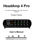
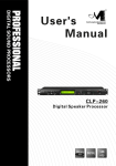
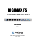
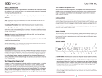
USB Dual Tube Pre
User’s Manual
IMPORTANT SAFETY INSTRUCTIONS – READ FIRST
This symbol, wherever it appears,
alerts you to the presence of uninsulated
dangerous voltage inside the enclosure. Voltage
that may be sufficient to constitute a risk of shock.
This symbol, wherever it appears, alerts
you to important operating and maintenance
instructions in the accompanying literature.
Please read manual.
Read instructions:
Retain these safety and operating instructions for future reference. Heed all warnings printed here and on the equipment. Follow the
operating instructions printed in this user guide.
Do not open:
Aside from two vacuum tubes, there are no user serviceable parts inside. Refer any service work to qualified technical personnel only.
Power sources:
Only connect the unit to mains power of the type marked on the rear panel. The power source must provide a good ground connection.
Power cord:
Use the power cord with the mains plug appropriate for your local mains supply as provided with the equipment. If the provided plug
does not fit into your outlet consult your service agent. Route the power cord so that it is not likely to be walked on, stretched or
pinched by items placed upon or against.
Grounding:
Do not defeat the grounding and polarization means of the power cord plug. Do not remove or tamper with the ground connection on
the power cord.
Ventilation:
Do not position the unit where the air required for ventilation is impeded. If the unit is to be operated in a rack, case or other furniture,
ensure that it is constructed to allow adequate ventilation.
Moisture:
To reduce the risk of fire or electrical shock do not expose the unit to rain, moisture or use in damp or wet conditions. Do not place a
container of liquid on it, which may spill into any openings.
Heat:
Do not locate the unit in a place close to excessive heat or direct sunlight, as this could be a fire hazard. Locate the unit away from any
equipment, which produces heat such as: power supplies, power amplifiers and heaters.
Environment:
Protect from excessive dirt, dust, heat, and vibration when operating and storing. Avoid tobacco ash, drink spillage and smoke, especially that associated with smoke machines.
Handling:
To prevent damage to the controls and cosmetics avoid rough handling and excessive vibration. Protect the controls from damage during transit. Use adequate padding if you need to ship the unit. To avoid injury to yourself or damage to the equipment take care when
lifting, moving or carrying the unit.
Servicing:
Switch off the equipment and unplug the power cord immediately if it is exposed to moisture, spilled liquid, objects fallen into opening, or the power cord or plug becomes damaged during a lightning storm or if smoke odor or noise is noted. Refer servicing to qualified technical personnel only.
Installation:
Install the unit in accordance with the instructions printed in the user guide.
II
INTRODUCTION:
Thank you for purchasing the ART USB Dual Tube Pre computer interface. Though it is very reliable and easy to use, we ask that
you take a moment to read the manual to get the best performance.
The USB Dual Tube Pre is a two channel professional quality audio interface that lets you connect microphone, instrument, and line
level signals to a mixer or other audio input as well as directly to your computer via USB or S/PDIF. This hybrid design is the latest
in a long line of ART tube preamps. We took our legendary Tube MP series and updated every aspect of the design, inside and out,
while still maintaining a compact, reliable, and cost effective product. From the all-aluminum stackable chassis to the precision LED
level metering circuitry, we have improved virtually every aspect of our already successful Tube MP series.
Included in this model are two different digital interfaces that add the ability to go direct to digital audio for connecting to virtually
any personal computer. The USB interface is supported by USB audio device drivers that are already built into Windows
98SE/ME/2000/XP/Vista/Windows 7 and Apple OS9.1/OSX computers. No special drivers are needed for basic operation. Just connect to the USB jack and your USB Dual Tube Pre will look like a USB Audio Device to your system. This gives you a totally isolated low noise audio interface for hard disk recording. A Separate S/PDIF jack allows a standard digital connection to various audio
interfaces.
The latest ultra low noise discrete microphone preamp front end has an extremely flat and wide frequency response and handles a
wide range of input signal levels with a minimum of coloration. This gives you a very clean and neutral sound with a wide variety of
signal sources. The high impedance 1/4” instrument input bypasses the microphone preamp circuitry to maintain a clean signal path.
We use a high quality 12AX7A tube inside to add warmth to musical dynamics and the analog section power supply is external to
keep AC line noise and hum back at the wall. The USB interface is isolated and powered directly off the USB port.
The input Gain control and switch helps to maximize your input dynamic range as well as control how hard you are driving the tube.
These two features are a must when trying to get the most out of a vintage ribbon or studio grade microphone. The switch selectable
Low Cut filter removes very low frequency rumble and wind noise before it has a chance to overload your inputs. The Bessel filter
design is set at a low 70Hz to preserve bass tonality and time domain response and it is very effective when tracking or interfacing to
your computer based audio workstation. Phantom power is available for the XLR input and is a clean +48 Volts DC from a low noise
internal supply that is current limited to prevent damage to your sensitive microphones.
An optical Compressor with fast attack and musical release times controls the maximum audio output level to prevent overloading
succeeding equipment. This allows you to maximize the dynamic range of your signal before converting to digital. A Phase Invert
switch lets you switch signal polarity right at the source. This is handy when you are mixing the signal output with other channels in a
mix.
The Output control comes after the Tube, Compressor and is used to match the output level to a wide variety of systems. Following
The Output controls are Insert Loop jacks and a bypass switch that allows adding effects and monitoring of the input signal.
Finally, a high performance output monitor section provides output signal drive capability to both balanced outputs and Headphone
output. This allows you to use the analog output jacks to directly monitor, with no latency, the signal that is going to digital via the
USB and S/PDIF interface and mix it with audio from your computer (via USB).
1
Key Features Include:
•
Two channel Tube based Mic/Instrument preamp computer interface
•
Extremely low noise discrete front end with variable input and output controls
•
Advanced optical output compressor to simplify recording and prevent overload
•
USB connectivity to desktop and laptop computers
•
S/PDIF output for expanding inputs on digital workstations and computer interfaces
•
Latency free Monitoring Mix and Level controls
•
Balanced XLR for lo-Z applications and 1/4” hi-Z inputs for instrument DI applications
•
Separate Gain, Phase Invert, Low Cut Filter and Compressor switches on each input
•
Selectable Dual or Stereo operation of output controls
•
Switch selectable Inserts on each channel
•
Insert jacks provide a preamp direct out for each channel
•
Stereo/ Dual operation of Optical Compressor
•
Mono switch for single input monitoring
•
S/PDIF Sample Rate switch selectable between 44.1K and 48K
•
Precision LED metering of both the preamp and A/D sections
•
Built-in low noise +48 Volt phantom power supply
•
Compact, stackable all aluminum chassis
2
Front Panel
LEFT GAIN and RIGHT GAIN knobs
These knobs adjust the input preamp gain for their respective channels. Use these controls to match the input signal to the levels required by the A/D and the outputs.
Increasing the LEFT or RIGHT GAIN will do a number of things. First, it will drive the tube more and create more tube warmth.
Second, it will optimize the discrete front end of the mic preamp for best noise performance. Finally, it will drive the OPTO COMP
harder when this function is used.
GAIN switch
Depressing the GAIN switch adds 20dB to the tube gain. This is useful when you need more gain than the input GAIN control can
provide. It also allows for more compression range of the Opto Compressor when required.
LOW CUT switch
The LOW CUT switch rolls off the response to signals lower than 70Hz. This helps to cut out low frequency rumble, wind noise, and
all types of very low frequency energy before it is amplified. When recording, this allows you to get more gain before clipping the
preamp, recorder, or computer and in a live situation you get more gain before clipping your amp.
PHASE switch
Use the PHASE switch to select the correct phase of the input signal to compensate for mic orientation and wiring. In the normal position, output signals are in phase with the input signal on all jacks.
This function comes in handy to prevent a hollow sound, due to phase cancellations, when using multiple microphones. In a live
situation you may be able to get more gain before feedback by reversing the phase of a vocal microphone.
OPTO COMP switch
This switch activates the Optical Compressor. The switch cap is lit Green when active and turns Red when gain reduction is taking
place. Use the OPTO COMP switch to compress the dynamic range of the input signal and prevent clipping of the A/D without
sounding obtrusive.
Note: The compressor threshold is affected by the LEFT or RIGHT GAIN controls and GAIN switches, but not the LEFT or RIGHT
LEVEL controls.
LEFT LEVEL and RIGHT LEVEL knobs
These controls provide a means of adjusting the output level of the preamps. These knobs are affected by the STEREO/DUAL
switch and can act as either independent controls or MASTER LEVEL and BALANCE controls.
3
SIGNAL/CLIP LEDs
These LEDs provide a means of measuring the output signal levels required for the A/D converters and to prevent clipping. The
LEDs monitor both the signal present at the preamp (pre LEFT or RIGHT LEVEL control) as well as the A/D converter (post LEFT
or RIGHT LEVEL control).
Note: Reducing the Level controls to 11 O'clock or less will provide a signal level /clip indication of primarily the input section. Do
this to check and see if the LEFT or RIGHT GAIN controls are set too high.
MONITOR MIX knob
This controls the proportion of the preamp signal vs. the D/A signal from the computer (via the USB jack) present in the monitor
jacks. When fully counter-clockwise, only the preamp signal is present with the computer signal muted. When rotated fully clockwise,
only the computer signal is present in the monitor output jacks.
MONITOR LEVEL knob
This controls the master stereo output level present at the Headphone or Monitor Output jacks.
MONITOR HEADPHONES jack
The Headphones jack on the front panel is an unbalanced version of the Monitor Output jacks on the rear suitable for driving headphones over a 1/8" mini-phone jack.
STEREO/DUAL switch
This switch controls the preamp LEFT/RIGHT LEVEL controls. Stereo mode changes the two knobs from independent control over
the two outputs to a Master volume (left knob) and Balance (right knob). This is useful when you have a stereo input signal and need
to control the level of both inputs at the same time.
OPTO link switch
This switch ties the gain of each channel's Opto Compressor together. This is required when controlling stereo sources so the stereo
image is maintained.
MONITOR switch
Depressing this switch will sum both input channels together for the Preamp source of the MIX control. This is useful when recording
a single input and listening to it through both left and right headphone or Monitor outputs while listening to a stereo return from the
computer (via USB). This switch does NOT affect the signal presented to the A/D converter or the INSERT jacks.
4
Rear Panel connections and controls
INPUT Jacks
The USB Dual Tube Pre INPUT jacks allow you to connect a low impedance source to the Mic preamp
through the XLR connection. If you use the 1/4" connection, the input connects to a high impedance unbalanced
instrument input amplifier. Gain of either type of input is controlled by the GAIN control on the front panel.
INSERTS jacks
The Left and Right INSERTS allow you to place external signal processing gear (like an EQ) between the preamp output and the A/D converter. The adjacent INSERT switch allows you to keep an external connection and
choose when to activate it.
The output of the unit connects to the tip of the 1/4” plug. The Ring connection is used as the input.
The INSERTS can also be used as preamp direct output jacks. Simply plug in a 1/4" unbalanced cable for this
output. Make sure that INSERT switch is in the Bypass position (out) to guarantee that the preamp signal is
passed on to the A/D and Monitor section.
INSERT switch
This switch allows the INSERTS jacks to keep external processors connected and enabled when depressed.
Note: When Using the INSERTS as outputs (using a mono 1/4" phone plug) the switch needs to be set to Bypass (out) to allow the
preamp signal to pass through to the A/D converters and Monitor section.
MONITOR OUTPUT jacks
The MONITOR jacks provide a balanced or unbalanced output signal suitable for driving line level signals over 1/4" cables. The
outputs contain the Preamp output mixed with the computer audio fed back through the USB connection. The outputs are controlled
by the front panel MONITOR Level and MIX knobs plus the MONITOR Switch.
5
S/PDIF Output
The S/PDIF connector allows the USB Dual Tube Pre to connect to a wide range of consumer and professional equipment. This output is .5V p-p (when connected) and has a 75 Ohm impedance. The S/PDIF output is controlled by the Rear SAMPLE RATE switch
and is independent of the USB sample rate. This output transmits a channel status identifying the correct sample rate and that copyright protection is turned off. Equipment driven by this output should be set to "slave" to this signal for correct timing syncronization.
The front panel SIGNAL/CLIP LEDs is calibrated to provide an accurate means of adjusting the preamp output levels for the best
A/D performance.
USB jack
The USB connection allows your USB Dual Tube Pre to send and receive audio from your computer. There is a separate A/D for the
USB interface that operates at a sample rate that is controlled by your computer. This interface is fully compliant with the USB 2.0
specification and is backward compatible with the USB 1.0 spec.
9 Volts AC POWER jack
The power connector on the rear should only be connected to the power supply that comes with the unit. 9 to 10 Volts AC @ 1000 mA
is required typically. Make sure that you specify AC and not DC if you have to replace this supply. Internal circuitry converts this
power to the higher voltages needed for the tube and phantom power sections.
POWER switch
This switch allows you to power off the unit when it is not in use. Please allow the tube and internal circuitry to warm up
for one to two minutes before use if the unit has been powered off.
S/PDIF SAMPLE RATE switch
This switch sets the sample rate for the A/D converter connected to the S/PDIF jack ONLY. When in the "out" positions the sample
rate is 44.1KHz. When depressed (lit), it sets the rate to 48KHz.
PHANTOM POWER switch
The PHANTOM POWER switch applies +48 Volt phantom power to the XLR input jacks for powering your microphones, if
needed. It is slow at turning on and off and is current limited to protect sensitive microphones and reduce pops. Ideally, when connecting a microphone that requires phantom power, you should first turn down the gain, then connect the microphone, then switch on the
phantom power, and finally bring the gain back up to the desired level. This minimizes pops in your system and stress on the microphone.
6
Block Diagram
7
APPLICATIONS:
Microphone Pre Amplifier:
The USB Dual Tube Pre is a high quality microphone preamplifier suitable for all dynamic, condenser, and ribbon microphones.
Most conventional mixers utilize budget minded microphone preamps and while very functional, they do not sound all that great. The
USB Dual Tube Pre serves as a quality upgrade that will give you more flexibility and a more robust tone than the standard preamps.
Simply plug a microphone into the XLR input. Apply phantom power if using a condenser mic. Then dial up the gain and you are
ready to go. Refer to the LEDs on the front panel for a visual measure of input gain, and then route the output to a mixer, workstation,
or computer via the 1/4-inch jacks or USB output. The overall analog output level can be adjusted right at the unit.
Phantom Power Supply:
Many mixers, workstations, and computer interface boxes will not supply +48 Volt phantom power on all the microphone inputs.
This is a critical feature if you plan to use a condenser microphone. The USB Dual Tube Pre is a perfect solution to this problem, letting you connect any microphone to the existing mixer or computer. Operation is identical to what is covered above.
Instrument DI:
The USB Dual Tube Pre will work well as a very functional Tube DI for bass, acoustic guitar and virtually any other instrument with
a 1/4” or XLR output. Many people prefer the sound of a tube for responsiveness and warmth instead of standard DI’s and preamps.
You will also enjoy more flexibility and control over a standard DI.
Operation is simple. Insert the output of the instrument into the input of the USB Dual Tube Pre. Make sure the volume on the bass or
guitar is up all the way. If you are using any effects, they can be patched into the INSERTS and then depress the INSERT switch.
Make sure that the overall output is not greatly increased when the effect is on. Adjust the input GAIN knob and refer to the SIGNAL/CLIP LEDs on the front for a visual measure of input gain. Then route the output to a mixer, workstation or computer interface
via the 1/4” or USB outputs. The overall Output and Compressor can be adjusted on the front of the unit. Both analog outputs and the
USB port may be used at the same time so that the 1/4” direct outputs can be routed to an amplifier, the 1/4" MONITOR outputs to a
monitor system and the USB to a computer.
8
SIGNAL/CLIP LEDs:
The USB Dual Tube Pre monitors the signal level at the tube output as well as the A/D inputs. This allows you to optimize the input
gain setting and also prevent clipping of the A/D.
If you keep the Output control above the 12 O'clock position, both the input and A/D levels are indicated.
To check the input signal level alone, turn the Output knob below the 12 O'clock position. This will reduce the output level to the
point where the input signal will dominate the LED display.
USB OPERATION:
Connect your analog jacks and external power supply first. If you are using one of the analog MONITOR outputs for local low latency
monitoring, connect that to your monitor system or headphones. Next, set the front panel controls for proper operation as per the previous sections. Then connect the USB cable to the appropriate input on your computer and lastly to the USB connector on the USB
Dual Tube Pre.
Once the USB connection is made and your computer is on, your computer will power the USB interface circuitry over the USB bus
and the unit will automatically connect and try to set your computer “Default Audio Device” to be “USB Audio CODEC”. Usually the
computer will do this automatically whenever a USB device is first connected, but it is sometimes necessary to make the selection
manually. The same settings may need to be made in your particular audio application as well (Check your application instructions).
These settings should be made while the two units are connected and powered on. Select one of the following sound recording (input)
settings:
WINDOWS 98SE: Settings => Control Panel => Multimedia
Choose the preferred device: “USB Audio Device”
WINDOWS XP: Settings => Control Panel => Sounds and Audio Devices => Audio.
Choose the mixer device: “USB Audio CODEC”
Or Programs =>Accessories =>Entertainment =>Volume Control=> Options=> Properties
Choose the mixer device: “USB Audio CODEC”.
WINDOWS Vista/ WINDOWS 7: Settings => Control Panel => Sound => Playback Tab and Record Tab.
Choose: “USB Audio CODEC”
Unlike previous versions of Windows, Windows 7 defaults to a single channel and adds too much gain to the signal coming though
USB audio devices. There are some things you will want to change in "Control Panel > Sound Settings" to get Windows 7 to work
with 2-channel USB audio products.
a) The default setting for the input is 1-channel / 16bit/44.1K. In "Properties", change this to: 2-channel/16bit/44.1K.
b) Windows sets the Mic input gain very high by default, so this needs to be reset.
c) Use the "Configure" button in the Sound window to access the Speech Recognition section and select "Set up Microphone" and
select "Other" under the input type.
d) Run a signal into the USB device and run the Windows 7 Speech Level Program, following the prompts.
After this, the gain levels will be appropriate, and both channels of the unit will be recognized.
Mac OS9.1 or OS X: Control Panels => Sound.
Under Input Device - Choose: “USB Audio CODEC”
Under Output Device - Choose: “USB Audio CODEC”
9
Your computer audio output “Speaker” is now set to be the “USB Audio CODEC” and playback audio is routed to the USB Dual
Tube Pre. This must be done while the USB Dual Tube Pre is connected to the computer and powered on. After the above settings are
made, your computer will automatically reconfigure itself back to these settings every time the USB Dual Tube Pre is reconnected to
the computer.
At this point your recording software will select and control which channels are being recorded and which channels are being monitored. There are many computer recording software packages available today that allow for multi-track recording. If you are using
multiple units and connecting more than one over the USB bus, they will appear as “USB Audio CODEC 1”, “USB Audio CODEC
2”, etc. in your recording application. Please refer to your recording software documentation for the best way to assign channels and
set recording and monitoring parameters.
Latency, the time delay between your audio input and the USB output to your computer, is very short (under 2 milliseconds) in the
USB Dual Tube Pre. The latency of your recording software and computer software drivers can be much more than this. Typically on
a Mac, the core audio interface has low latency so this is usually not an issue. USB audio drivers that come with Windows can have
enough latency to cause a discrete delay when monitoring live. If this becomes an issue there are low latency ASIO drivers available
that can greatly reduce your Windows audio latency. Two current resources for low latency ASIO drivers that will work with the USB
Dual Tube Pre are: www.asio4all.com and www.usb-audio.com
S/PDIF OPERATION:
The S/PDIF output allows connection to various workstations and audio interfaces. This output consists of two channels of 24-bit digital audio plus some data describing the data (Channel Status or CS). The digital audio data source is the A/D converter. You can access this A/D directly by patching into the Insert input jacks "Ring" terminal.
If you are having trouble with this interface, make sure that the input you are connecting to will accept "consumer" mode digital audio
data, and you have selected the same sample rate in your application the USB Dual Tube Pre is set to (i.e. 44.1K or 48K).
A brief note from customer service:
Once in a while a customer will call and say: I think my ART preamp is "noisy". What's wrong?
If you experience unwanted "noise" in your system when you use a stand-alone preamp, please consider what your signal is and where
you're sending it. Some people send the signal from their preamp to a mic input (they figure, "Well, I'm using a mic!") on the board or
recorder. This is in fact incorrect and could create higher overall noise. ART preamps are actually intended to output a nice fat LINE
LEVEL signal. If you send that line level signal to a recorder's or mixer's Mic input, that circuit will usually add more gain to the signal. Gain on top of gain will indeed result in noise. Please treat the output signal as line level and you'll be pleasantly surprised at your
new clean and warm sound.
The same rule applies for guitar and bass players that use ART preamps as their front end. Send the signal from your preamp to a low
gain input on your amp, or even a "loop return" jack which allows you to bypass the amp's solid state preamp altogether.
10
SPECIFICATIONS:
Input Connections: .............................................XLR / 1/4-inch “Combo” jack - XLR balanced or 1/4" unbalanced
Input Impedance: ................................................1M Ohms 1/4-inch input, >4K Ohms XLR input, 20K Ohms Insert Input
Output Connection: ............................................1/4-inchTRS balanced, 1/8-inch TRS headphone mini jack
Output Impedance: .............................................600 Ohms (balanced 1/4-inch), 300 Ohms (INSERTS), < 50 Ohms (headphone 1/8inch)
Frequency Response: ..........................................20 Hz – 27K Hz (+0, -1 dB)
Maximum Gain:..................................................+65 dB (balanced in-out), +45dB (unbalanced input, balanced output)
THD: ...................................................................<0.01% @ 1K Hz
CMRR:................................................................>60 dB
Equivalent Input Noise: ......................................-129 dBu typical (“A” wtd., Shorted XLR balanced input, gain @ maximum)
Maximum Input Level: .......................................unbalanced (Inst): +16 dBu, balanced (mic): +12dBu, Insert input : +7.5dBu
Max Output Level:..............................................unbalanced: +5dBu, balanced: +11dBu, +7.5dBu (insert output)
Phantom Power:..................................................Switch selectable, +48Volts DC, filtered, current limited
Tube Type...........................................................Hand Selected 12AX7A
Compressor Slope:..............................................progressively increasing slope, 10:1 max.
Compressor Range:.............................................28dB of attenuation max.
Low Cut Filter.....................................................-3dB @ 70Hz, 6dB/Octave
USB A/D-D/A: ...................................................16 Bit, 44.1K Hz or 48K Hz, USB selectable from computer, 0.4 ms A/D latency @
44.1K Hz
S/PDIF A/D: .......................................................24 bit, 44.1K or 48KHz switch selectable, 0.4 ms A/D latency @ 44.1K Hz
Computer Interface: ............................................USB 2.0 compliant, Windows 98SE/ME/2000/XP/Vista,Win 7, Apple OS9.1/OSX
computers with native USB support
Chassis Type:......................................................All aluminum black anodized with integral rubber sides
Power Requirements: ..........................................9VAC @ 1000mA (external)
Dimensions: ........................................................1.75”H x 5.9”W x 6.5”D (44.5mm x 150mm x 165mm)
Weight: ...............................................................2.5 lbs. (1.14 kg) with power supply and packaging
Note: 0 dBu = 0.775Vrms
12