1
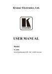
482mm 19" DIGITAL USB Index Index........................................................................P age 1 Safety Instructions.....................................................Page 2 Controls and Parameters............................................Page 3 CLP260 Processes Notes...........................................Page 4 RMS Compressor......................................Page 4 A.G.C...................................................... Page 5 PEAK Limiter............................................Page 6 Sub Harmonic Synthesizer.........................P age 7 Input and Output Level Considerations........................P age 8-10 Getting Started..........................................................P age 11 Encoders and ENTER/QUIT buttons............................P age 12 Load/Save Preset......................................................P age 12-14 Utility Function..........................................................P age 15 Edit Parameters........................................................ Page 16 Routing....................................................P age 16 Input Gain................................................Page 16 Noise Gate...............................................P age 16 A.G.C.......................................................P age 17-20 Filters 1-7.................................................P age 21 Sub Harmony............................................P age 22 Drive........................................................P age 23 RMS Compressor......................................P age 24-25 Make Up.................................................. Page 25 PEAK Limiter............................................P age 26 Mute........................................................Page 26 Appendix 1............................................................... Page 27 Input Level Meters Ref. Table.....................P age 27 Comprressor/Limiter Activity......................P age 28-29 Meters Ref. Table......................................P age 29 CLP260 Processes Block Scheme...............................P age 30 1 IMPORTANT SAFETY INSTRUCTIONS Note: in order to ensure safety, please read these instructions carefully All safety and operating instructions should be read before the product is operated. Attention:To reduce the risk of fire or electric shock, do not expose this apparatus to rain or moisture! 6 Objects or liquid entry 1 Ventilation inside the unit Do not block any ventilation openings. Be careful that no objects fall or liquid is spilled inside the unit through ventilation openings. 2 Cleaning Clean only with dry cloth. 7 Humidity The unit should far away form water. 3 Heat sources Do not install near any heat sources such as radiators, stoves, or other apparatus that produce heat. 8 Maintenance Refer all servicing to qualified service personnel. To prevent the risk of shock, do not attempt to service this equipment yourself because opening or removing covers may expose you to dangerous voltage or other hazards. 4 Power cord proctecion Protect the power cord from being walked on or pinched particularly at plugs. 5 Overload Power plug should not overload. 2 CLP-260 RMS Stereo Compressor CONTROLS Enc Variation Key Enter Key Quit Led Clip Enc Navigation Button Process On/Off Pot Input Level Pot Output Level Adjust Parameters Value Access to Editing Pages and Par Values Confirm Exit from Editing Pages Input/Process Overflow Compressor's Ratio and Knee selection RMS Compressor Active/Bypass Analog Input Gain Left/Right Analog Output Volume Left/Right TECHNICAL DATA Inputs Balanced 2 TRS/2 XLR Outputs Balanced 2 TRS/2 XLR Input Max Level +15dBu Output Max Level +10dBu THD+N <0.01% @ -6dBFS (Bypass) S/N Ratio >100dBu (Processes in Bypass) Frequency Response 20Hz – 20kHz +/-0.5dB A/D and D/A Resolution 24bit Process Resolution 24x48 bit Processes RMS Stereo Compressor Power Supply 110V/220V (Switchable) 2x20 characters LCD display for the Parameters Editing Fully remotely controllable by USB or MIDI interfaces 3 1 The CLP260 is a Stereo RMS Compressor and Peak Limiter with the addition of a Noise Gate, an AGC, a 7 bands Eq and a Sub Harmonic Synthesizer. With reference to the following RMS Compression process representation The CLP260 is implementing a REAL RMS Compressor, so compressing at the same threshold a pure sinusoidal signal as a squared wave. Particularly, the RMS Compressor is a Compression process applied with fast slow Attack and Release times to the INPUT signal of a Unit, in order to maintain the amplitude of the OUTPUT signal at a defined level, when input level is exceeding a defined intervention Threshold. The Compressor implemented in the CLP260 is acting on the evaluation of an input signal which is an averaged one on a 50ms time frame, and representing actually the RMS value of the input signal itself, so to make more “Musical” the Compressors action. The RMS Compressor, it is so maintaining constant the output energy and not the Output peak, so to have for the different inputs, independently from their harmonic content, a constant output RMS level. More, for the CLP260 Compressor is also available a Ratio and a Hard/Soft Knee parameters. The Ratio parameter is allowing to get a compressed output maintaining a constant dB ratio with the input. This feature is got in the CLP260 with a precise Look Up Table Log Computation process, allowing int the ratio maintenance a precision of 0.1dBu. 4 The Hard and Soft knee feature is allowing the user to select between a sudden compression intervention when the input signal it is just above the Threshold (Hard Knee) or a smoother one starting the compression smoothly before the Threshold., Together with the RMS Compressor, the CLP260 is making available also other 2 very useful Dynamic Processes: an AGC and a Peak limiter. In order to understand how the CLP260 AGC is working, need to refer to the following picture The AGC is an Expansion/Compression process applied with pretty slow Attack and Release times to the INPUT signal of a Unit, in order to maintain the average amplitude of the OUTPUT signal at a defined level, independently from the averaged amplitude of the input sources. For this purpose, the AGC has to be able to expand the input signal, there where the average of the related output signal is below a defined Threshold (Exp Thr), and to maintain the expanded signal at a constant expansion level when the averaged signal is beyond a defined Threshold (Thr Hold). The AGC implemented in the CLP260 is acting on the evaluation of an input signal which is an averaged one on a 50ms time frame, and representing actually the RMS value of the input signal itself, so to make more “Musical” the AGC action. If the output signal of the AGC process will exceed then a defined Threshold (Cmp Thr), so becoming too loud, a compression process is occurring. 5 The Speed and the amount of the Expansion can be defined through the “Exp Time' and “Exp Ratio” parameters, so as the Speed and the amount of the Compression can be defined through the “Cmp Time” and “Cmp Ratio” parameters. When the Signal coming out from the AGC process (Output), applied to the AGC input, is above the “Exp Thr” and below the “Thr Hold”, it is expanded up to the max expansion coefficient defined by the Exp Ratio. When the Signal coming out from the AGC process (Output), applied to the AGC input, is above the “Cmp Thr”, it is compressed up to the min compression coefficient defined by the “Cmp Ratio”. When the AGC output is comprised within the “Thr Hold” and the “Cmp Thr” Thresholds, no further expansion or compression actions will be taken and the expansion/compression coefficient, will be maintained with its current value. Particularly, if the averaged AGC output level is “entering” the signal “hold” area coming from the expansion area, then the Coefficient computed by the AGC for multiplying the input level in order to get the proper output signal, will be higher than one (if the “Exp Ratio” will be set at 1:2), so as the coefficient will be lower than one (if the “Cm Ratio” will be set between 2:1 and 16:1) if the averaged AGC output level is “entering” the signal “hold” area coming from the compression area. The last dynamic process available with the CLP260, is a Peak Limiter, useful when the CLP260 is used before an amplifier and need to limit the signal for avoiding the amplifier to overload and break cabinets. This kind of Limiter is acting on the Signal Peak detection and therefore the limitation is on the output Peak value. 6 In addition to the Dynamic Processes, in the CLP260 is also available a powerful Sub Harmonic synthesizer. The Sub Harmonic Synthesizer is working generating sub Harmonics on the base on the Harmonic content of the original signal. Particularly, the amplitude distribution of the generated Sub Harmonics is following the shape of a band pass filter set on the low part of the band. The peak of this “band pass” filter, is centered on 2 possible frequencies, 60Hz and 90Hz.; this means that when selected the frequency range setting the Sub Harmonics Amplitude Peak on 60Hz (24-36Hz), the Harmonics added to the original sound will bring a “deep” and very low extra body to the original sound. When selected the frequency range setting the Sub Harmonics Amplitude Peak on 90Hz (36-56Hz), the Harmonics added to the original sound will bring a “lighter and more booming” extra body to the original sound. Finally, in order to “adjust” harmonically the Input signal, a 7 bands Eq. is available, where the first of the 7 filters can be chosen to be 1st/2nd ord. HP or Low Shelving, the seventh one can be chosen to be 1st/2nd ord. LP or High Shelving and the other 5, from the second to the sixth, can be chosen to be 1st/2nd ord. High Shelving or Peaking. The CLP260 has a bypass control in the analog domain. 7 Input and Output Level Considerations The Input and Output levels of the CLP260 can be adjusted by a couple of Analog Potentiometers. Due to the fact that the potentiometers are operating in the analog domain, before the A/D converter ( Input Level) and after the D/A converter (Output Level) there is not an absolute and fixed relation between the Input and Output Levels and the levels in front of the A/D and after the D/A converters. Need therefore to provide the user some “Absolute” reference in terms on Input level and Output level, in order to clarify first what are the Max Absolute Input level, which cannot be exceeded without getting an OpAmp clip, no longer recoverable by any Digital operation. In order to help the user in understanding clearly the following paragraphs, need to refer to the “Input Level” and “Output Level” pictures, replicating the Input and Output Potentiometers' grids with a more precise detail: Fig A Fig B The figures A/B are showing in details the possible positions of the potentiometers controlling the Analog Input and Output Level. Referring then to the above precise divisions of the available range between the MIN and MAX position of the potentiometers, the Max Analog Input/Output levels can be understood, so as the can be found the proper setting for the best use of the RMS Compressor. 8 In order to verify the Input/Output Max Levels of the CLP260, need first to make sure that NO process is active. Max Analog Input: in order to understand what can be the maximum Analog Input level to the unit, which is the one before the clipping of the Op-Amps in front of the A/D converters, need to make sure that no Digital clip (DSP process) is occurring. The output will never clip unless the clip is coming from the digital process. This means that if the D/A output isn't clipped, then no clipping will come from the Analog Op-Amp output section. From this point of view, any position of the Output potentiometer for evaluating the Max Input level, can be set. Let's consider to set the output potentiometer to the position 5 of the grid in Fig B. Now, to define what is the Max Analog Input level, need to set the Input Level potentiometer to a position granting enough attenuation of the signal before the A/D, so to make sure no clip is occurring on the A/D side. Let's set the Input potentiometer to the position 3 of the grid of Fig. A. Done this, we can increase progressively the Input signal level until the output will start to clip or the Input Level displayed on the LCD will not show the “>” symbol. In this way, can be found that the Max Input level, before to get the Input Op amps clipping is +15dBu. Max Analog Output: once set the Max Input Level to +15dBu, in order to identify the Maximum Output Level, need to move the Input Level Potentiometer from the position 3, up to the position that is clipping the A/D converter. With +15dBu Input, the position of the Input Level Potentiometer at the limit of the Input Clipping, is the position 6 of the Input Level grid of Fig A. Once set, then, the Input Level Potentiometer to the position 6, in order to find out the Max Output Level achievable with the CLP260, need to set the Output Level Potentiometer to the position Max The Max output Level that can be found is +10dBu, if measured with an Audio Precision or similar measurement tools. CLP260 Signal to Noise Ratio (S/N): from the condition got for the Max Analog Output verification, can be go the S/N of the CLP260. If, with the Max Output Level of +10dBu, the Input Signal Is removed, measuring the output can be seen that the residual Ground Floor Noise drops to -92.7dBu, which let us say that the S/N=(Max Output) – (GND Floor Noise) = 10dBu - (-92.7dBu) = 102.7dBu 9 Analog Bypass: de-pressing the “On/Off Process” button, the Analog Bypass can be activated. In this condition the CLP260 is bypassing the Digital section and connecting the Analog Input to the Analog Output. Here the Max Output is reaching the +10.4dBu with a GND Floor Noise of -92.3dBu, bringing the S/N of the unit to 102.7dBu Set Input and Output Potentiometers for a 0dBu Input/Output path: in order to evaluate the performances of the CLP260 RMS Compressor, we'll set a 0dBu path, and to that one we'll refer the all measurement we'll show for making understanding the Unit's way of working. What anyway will be shown, will remain valid for any input level value there where with the Input Level Potentiometer, the signal to the A/D will be adjusted so to be close to the Clipping (notified by the RED CLIP Led or by the symbol “>” Input Level page on the LCD). In order to be on a 0dBu Input/Output path, when the Unit is in “Process Bypass”, need from the previous condition to set the external Analog Input Signal to 0dBu. In order to get in Output also 0dBu, being at the maximum A/D Input level, need to set the Input Level Potentiometer to 7 of the Grid of Fig A and the Output Level Potentiometer to the position 7 of the Grid of Fig B. The Input Level page on the LCD will just stop a step before the showing of the “>” symbol. To the 0dB path condition are referred the AGC, RMS Compressor and Peak Limiter's Thresholds that when set to 0dB are meaning that the processes are not active being the Threshold set at the maximum input level to the unit...which cannot be exceeded, impeding therefore any compressing/limiting process. This means the the 0dB threshold of the AGC, RMS Compressor and Peak Limiter processes are related to the max Input level and therefrom has to be evaluated the threshold set when using a threshold different from 0dBu: in example a -10dBu Threshold on the RMS Compressor means that starting from an input reaching the max input level, this input will be limited at 10dBu lower RMS level. 10 Getting Started As soon as the CLP260 is turned ON the device model name will appear in the LCD screen: CLP260 Compressor Limiter And after showing quickly the “Firmware Version 2.212”, the LCD will show the “Input Level Page, by default, where is possible see thanks to graphic meters, the Input level When the Input Level is in clipping, the symbol”>” will appear (as for the channel B in the example) From this initial condition, and if an RMS Compressor or a Peak Limiter (or both) are set to be active, their compression/limiting activity can be seen thanks to a the “Compressor Activity” and “Limiter Activity” windows, accessible from the Input Level one just rotating the NAVIGATION encoder clock/counter-clock wise. If in example from the Input level window the user want to see the RMS Compressor's activity, it is enough to rotate the NAVIGATION Encoder clockwise twice, so accessing the following screen: Where the compression activity is shown from right to left, matching the depth of the compression on the base of the Compression Coefficient Value: if the coefficient is equal 1, then no compression is occurring and no bars are displayed, if the coefficient is <1, then as more the coefficient is far from 1 as more from right to left bars will appear. For the relation between the bars in the Input Level, Compression/Limiting Activity windows and the Input signal level and compression depth, refer to the Appendix 1 tables. 11 Encoders and ENTER, QUIT buttons The CLP260 is equipped with 2 Relative Encoders, “VARIATION” and “NAVIGATION”, These encoders allow to navigate the user interface and edit sections of the processor. They allow the user to navigate within the screen for the selection of sub-menus, pages and parameters and to select the values to be assigned during the editing operations. The “ENTER” and “QUIT” buttons allow the user to confirm or NOT confirm the operations performed by the encoders. Particularly, the “ENTER” button is also allowing to enter the editing pages from the initial Input Level and Compressor/Limiter Activity screens. The “QUIT” button is allowing to get back from any editing page to those screens. From anyone of the Initial windows, the editing menus and pages can be accessed pressing the “ENTER” button. Once left the Input Level and Compressor/Limiter Activity windows, the screen will show on the top row the currently running preset and it's n a m e , a n d o n t h e l o w e r r o w, t h e s u b - m e n u f o r t h e C L P 2 6 0 functions/parameters access and editing. Once left the Input Level and Compressor/Limiter Activity windows, if the currently running preset is the number 16 called “DeepCmp”, the screen will then appear as follow: Preset 16: DeepCmp Load Preset And to access the all sub-menus need just to rotate clock/counter-clock wise the NAVIGATION Encoder. The all available Sub-menus are: Load Preset: Loading one of the 32 available presets (16 factory and 16 users) Save Preset: Store up to 16 user presets Utility Function: Communication Interface setting (USB or MIDI) Edit Parameters: Access to the parameters' editing of the all CLP260 processes 12 Load Preset: this page allows the Loading of a preset program from one of the 16factory presets (1-16) or from one of the 16 user presets: Preset 16: DeepCmp Load Preset By pressing ENTER and rotating the “VARIATION” encoder, it is possible to scroll through all current available user presets. Load Preset <Preset:21 AGC_Fat > If the Preset 21 is chosen (AGC_Fat), then pressing the “ENTER” button, the current temporary window will appear Wait : Loading …... <Preset:21 AGC_Fat > and the AGC_Fat preset number 21 will be loaded and the sub-menu page will be left going back to the previous level, updated: Preset 21: AGC_Fat Load Preset Save Preset: this page allows you to store a new preset, and up to 16, in the CLP260's memory from the location 17 up to the location 32, skipping the locations from 1 to 16 reserved to the Factory presets: Preset 21: AGC_Fat Save Preset By pressing the ENTER button and rotating the “VARIATION” encoder, it is possible to scroll through the previously saved presets and the available empty locations (identified by “Empty”). If no user presets are stored, the “Save a Program” screen will show empty memory locations for all 17-32 presets as shown in the example below for location 30: 13 Save Preset <Preset:30 EMPTY > When storing an edited configuration for the CLP260, select the location for a preset from the 16 available by using the “VARIATION” encoder. Once the desired location appears on the screen press ENTER again to reach the “Edit Name Preset” page. If the location number 30 is ok, in example, then the screen will be the following: Edit Name Preset 30: _preset name In this page the User can enter a Preset Name (up to 16 Characters) by using the “VARIATION” encoder to choose a character and the “NAVIGATION” encoder to move between the 16 available locations for the character's positioning. The current position of the cursor is shown by a “blinking underscore”. To store the Preset Name press the “ENTER” button again. The above action will take you to the “Enter to Save” page showing the selected location for the preset and the final edited name, in example LightCmp: [Enter] to Save 30: LightCmp Pressing “ENTER” again, will store the preset in the selected location with the chosen name and the following transitory screen will appear on the LCD: Wait : Saving …... 30: LightCmp Once saved the preset, the CLP260 will go back to the previous level Preset 30: LightCmp Save Preset 14 Utility Function: this sub-menu allows to define the remote control interface [USB or MIDI] to be used for controlling the CLP260 : Preset 30: LightCmp Utility Function From “Interface Utilities”, press “ENTER” to access the “Config Communication” page, allowing to choose the remote control protocol for the CLP260. Utility Function Config Communication By pressing “ENTER” and then using the VARIATION encoder, can chosen between the two possible interfaces (USB or MIDI) for the CLP260. Particularly, a MIDI channel from 01 to 15 can be selected, or the USB interfaces Config Communication Device <MIDI Ch=12> Once selected the desired interface, a double click on the “QUIT” button is allowing to go back to the original menu. NOTE: the “QUIT” button, once pressed as many time as necessary, will bring back to the top LCD level which is the one displaying the Input Level or the Compressor/Limiter Activity. 15 Edit Parameters: in this sub-menu, the all parameters related to the signal processes of the CLP260 are available for editing. Pressing the “ENTER” button, the all processes can be accessed for editing. With the “NAVIGATION” Encoder, the all processes can be scrolled and from the “Edit Parameters” Sub Menu, the CLP260 channel can be selected for editing simply rotating clock/counter-clock wise the “VARIATION” encoder. Once entered the Edit Parameter Sub Menu, the screen will show the following: Ch.A Edit Param Routing In the case above, editing the all parameters edited are referred to the Channel A (ChA); for editing the processes referring to the Channel B (ChB), it is enough to rotate the VARIATION encoder and the screen will show the following: Ch.B Edit Param Routing Indicating that the Parameters will be edited will refer to the ChB process and Output. It is also possible select the Ch.A+B, and in this case the all edited parameters will be assigned with the same value to the Channel A and B ..linked. In the Editing Parameters Sub-menu, the all available processes are: Routing: is allowing to assign the the currently edited channel processes the Input A, B or the Sum (A+B)/2 Input Gain: Digital control of the Input level Noise Gate A.G.C. Filter 1 – Filter 7: Eq where the filter 1 is selectable as 1st/2nd Ord. HP OR Low Shelving and the filters from 2 to 7 as 1st/2nd Ord. High Shelving OR Peaking Sub Harmony: Sub Harmonic Synthesizer centered around 65Hz or 90Hz Drive: Signal Control before the RMS Compressor RMS Compressor Volume: Make Up Volume after the RMS Compressor and before the Peak Limiter Peak Limiter Mute: Output Channel Muting. 16 In order to edit the parameters of any single process, it is enough to enter the process editing page by pressing the “ENTER” button and leaving it, once finished the editing, by pressing the “QUIT” button for going back to the Editing Parameters sub-menu and selecting the new process to edit, scrolling the all processes with the NAVIGATION encoder. Routing: from this page it is possible to assign anyone of the 2 inputs of the CLP260 to the currently edited Channel's processes and Output. So, it is possible to assign to the processes of the Channel A and its Output, the Input A, B or (A+B)/2. The selection can be operated using the VARIATION encoder. Input Gain: from this page it is possible to adjust the Input Level digitally (after the A/D converters) ranging from -12dBu up to +6dBu, by steps of 0.5dBu. The adjustment can be operated using the VARIATION encoder. Noise Gate: from this page it is possible to set the parameters of a Noise Gate placed at the beginning of the all dynamic and Eq. Processes Threshold: the Noise Gate Threshold can be set as -80dBu, -85dBu, 90dBu or as OFF; when OFF the Noise Gate is just bypassed Release Time: it is the time taken by un-muting the output once detected again an input signal over the set threshold; can range from 5ms to 100ms, by steps of 1ms up to 10ms and of 10ms from 10ms up to 100ms. Attack time: is the time taken by the Noise Gate to enter the Output Mute condition once the input signal is detected to be below the Threshold; can range from 0.5 seconds up to 2 seconds by steps of 0.1 seconds. The adjustment of the parameters can be operated using the VARIATION encoder. Ch.A Noise Gate < Attack = 0.5s 17 > Note: for the all Dynamic Processes as the AGC, RMS Compressor and Peak Limiter, it is necessary, in order to make them working properly, to be in a condition similar to the one described before for the 0dBu path. Any different condition on the Input Signal, can bring to the same output results if the Input Level Potentiometer will be Adjusted in order to be close to the Input Clipping condition, which means that if the Input Signal will be lower/higher than 0dBu, the potentiometer will have to adjust the input to the A/D converter so to go back to a “0dBu” condition as the one used as reference. A.G.C.:from this page it is possible to set the parameters of the Automatic Gain Controller. AGC Bypass: from this screen it is possible to set the AGC On or OFF, so to activate it or not without resetting the all parameters; use the “VARIATION” encoder for toggling the AGC Bypass On/Off. The following is an example screen for the “AGC Bypass” page where the AGC is set Active Ch.A A.G.C. < Bypass = ON > AGC Exp Time:from this screen it is possible to set the AGC Expansion time from 0.057 seconds up to 14.4 seconds; use the “VARIATION” encoder to set the value. The following is an example screen for the “AGC Exp time” page where the Expansion Time is set to 1.5S AGC Cmp Time: from this screen it is possible to set the AGC Compression time from 0.014 seconds up to 6 seconds; use the “VARIATION” encoder to set the value. The following is an example screen for the “AGC Cmp time” page where the Compression Time is set to 0.5S 18 AGC Exp Thr: from this screen it is possible to set the AGC Expansion Threshold from -70 dBu up to the Hold Threshold Value; use the “VARIATION” encoder to set the value. The following is an example screen for the “AGC Exp Thr” page where the Expansion Threshold is set to -50dBu Ch.A A.G.C. < Exp Thr =-50dB > AGC Cmp Thr: from this screen it is possible to set the AGC Compression Threshold from Hold Threshold Value up to 0dBu; use the “VARIATION” encoder to set the value. The following is an example screen for the “AGC Cmp Thr” page where the Compression Threshold is set to -3dBu AGC Thr Hold: from this screen it is possible to set the AGC Threshold of the AGC Signal “Hold” area, from -69 dBu up to -1dBu; use the “VARIATION” encoder to set the value. The following is an example screen for the “AGC Thr Hold” page where the Threshold of the Signal “Hold” area is set to -40dBu 19 AGC Exp Ratio: from this screen it is possible to set the AGC Expansion Ratio from 1 up to 2; use the “VARIATION” encoder to set the value. When the Expansion Ratio is set to 1, actually there is no possibility to expand the signal, meaning that the signal amplitude can be multiplied for a coefficient not higher than 1. If the Expansion Ratio is set to 2, the signal can be expanded up to a max amplitude that is twice the original one. The following is an example screen for the “AGC Exp Ratio” page where the Expansion Ratio is set to 2 and the Signal can be expanded up to the double of its original amplitude Ch.A A.G.C. < Exp Rto = 1:2 > AGC Cmp Ratio page – from this screen it is possible to set the AGC Compression Ratio from 1 up to 16; use the “VARIATION” encoder to set the value. When the Compression Ratio is set to 1, actually there is no possibility to compress the signal, meaning that the signal amplitude can be multiplied for a coefficient not smaller than 1. If the Compression Ratio is set to 2 or more, the signal can be expanded up to a min amplitude that is depending from the ratio and can reach the 1/16th of the original signal amplitude. The following is an example screen for the “AGC Cmp Ratio” page where the Compression Ratio is set to 4 and the Signal can be compressed up to 1/4th of its original amplitude Ch.A A.G.C. < Cmp Rto = 4:1 20 > Filters 1-7: the CLP260 is providing also a 7 bands Eq. For the adjustment of the Input Signal. Particularly, the first filter of the Eq. Can be selected to be a 1st/2nd Ord. Hp or a 1st/2nd Ord. Low Shelving, the seventh filter can be selected to be a 1st/2nd Ord. Lp or a 1st/2nd Ord. High Shelving and the filters from the 2nd to the sixth are Peaking ones. Filter 1: the filter 1 is a filter selectable between a 1st/2nd Order Butterworth High Pass or a 1st/2nd Order Low Shelving, or the filter can just be bypassed. The parameters selectable using the NAVIGATION encoder are the following Type: here the filter type can be selected or just bypassed Frequency: with the VARIATION encoder the cutting frequency of the filter can be set ranging from 20Hz to 20kHz by steps of 1/12Oct. Amplitude: if a Low Shelving filter is selected, here can be set the filter's gain, ranging from -6dBu up to +6dBu. Filter 2-6: the filter 2-6 are Peaking filters. The parameters selectable using the NAVIGATION encoder are the following Q-Type: here the filter's Q can be set ranging from 0.05 up to 2.00 by steps of 0.05. Frequency: with the VARIATION encoder the cutting frequency of the filter can be set ranging from 20Hz to 20kHz by steps of 1/12Oct. Amplitude: here can be set the filter's gain, ranging from -6dBu up to +6dBu. Filter 7: the filter 7 is a filter selectable between a 1st/2nd Order Butterworth Low Pass or a 1st/2nd Order High Shelving, or the filter can just be bypassed. The parameters selectable using the NAVIGATION encoder are the following Type: here the filter type can be selected or just bypassed Frequency: with the VARIATION encoder the cutting frequency of the filter can be set ranging from 20Hz to 20kHz by steps of 1/12Oct. Amplitude: if a High Shelving filter is selected, here can be set the filter's gain, ranging from -6dBu up to +6dBu. 21 Sub Harmony: the Sub Harmonic Synthesizer is a particular process, already introduced in the first part of the manual, that isn't actually related to the RMS compression one. The Sub Harmonic Synthesizer is intended to be an “extra” process available to the user there where the RMS Compressor is chosen for processing a source addressed to a “background” use as in clubs or similar. There, the possibility to have synthesized basses in order to extend the band also when the musical program is poor of harmonics on the low frequencies, can help in improving the quality of the background music and to gain a "heavier" or more vibrant sound. The Sub Harmonic Synthesizer is a process synthesizing the first lower harmonic of the frequencies ranging from 40Hz to 500Hz, detected in the original signal. This means that there where in the original signal are detected frequencies from 40Hz to 500Hz, sub harmonics from 20Hz to 250Hz are generated. Fig. F As can be seen in the Fig F, however, the synthesized sub harmonics are not generated in the low harmonics' band with the same amplitude, but with a Peak on 65Hz or on 90Hz and then with decreasing amplitude going up from 65Hz/90Hz to 250Hz and down to 20Hz. 22 This is due to the fact that extend the same amplitude to the all sub harmonics generated, would bring to a “booming” and “dark” result, there where having a Peak on the 65Hz(24-36) or 90Hz(36-56), will leave the max intensity of the synthesized sub harmonics, in correspondence of the original fundamentals, ranging around 130Hz and 180Hz, where typically fall the octave used by the harmonizing instruments as the Bass or Kick Drum, creating there a bigger presence and giving the music that much sought after "punch". The all available Parameters of the Sub Harmonic Synthesizer, accessible by the Unit's Front panel, using the NAVIGATION encoder for scrolling them and the VARIATION encoder to set their value, are the following: Ch.A < Freq = Harmony 36 -56 Hz > Percent: With this parameters can be set the amount of Sub Harmonics generated, will be added to the original Signal. Freq: this parameter is allowing to select what's the Peak of the Synthesized sub band; when selected 24-36, the Peak is centered on 65Hz and the max amplitude is +18.6dBu, when instead 36-56 is selected, the Peak is centered on 90Hz and the Max amplitude is 15.7dBu. Drive: within this page is possible to set the signal level BEFORE the RMS compressor Peak detector. The Gain can be set ranging between -12dBu and +6dBu, by steps of 0.5dBu: The Drive is not increasing actually the Input Signal level, but just the one of the signal used as reference for the RMS Compressor RMS detector. This means that acting on the Drive the Original Input Signal isn't affected, but the level “seen” by the RMS level detector yes. Operating on the drive, then, it is possible to get on the Input Signal a higher level of compression, still remaining its level the original one. In some way the Drive is allowing to extend of 6dB more the compression range, or reduce it of 12dB. 23 RMS Compressor: the RMS compressor, which way of working has been described yet in the introduction, can be controlled in its parameters entering the editing screens and scrolling the parameters with the NAVIGATION encoder and setting them with the VARIATION encoder: Threshold: from this page it is possible to set the Threshold parameters of the RMS Compressor. Once within the page, the RMS Compressor's Threshold can be set by the VARIATION encoder: The selectable range of the RMS Compressor's Threshold is from 0dBu (OFF) to -24dBu in steps of 0.1dBu Ratio: from this page it is possible to set the Ratio parameters of the RMS Compressor. Once within the page, the RMS Compressor's Threshold can be set by the VARIATION encoder: The selectable range of the RMS Compressor's Ratio is from 1:1 (Off) up to 32:1 (Lim) in steps of 1. H/S Knee: from this page it is possible to set the “Knee” type of the RMS Compressor. Once within the page, the RMS Compressor's Threshold can be set by the VARIATION encoder: The selectable range of the RMS Compressor's Knee type is from 0% (Hard) up to 100% (Soft) by steps of 1. 24 Release: from this page it is possible to set the Release Time parameters of the RMS Compressor. Once within the page, the RMS Compressor's Threshold can be set by the VARIATION encoder: The selectable range of the RMS Compressor's Release Time is from 0.1s to 5s in steps of 0.1s up to 3s and 0.2 from 3s to 5s. Attack: from this page it is possible to set the Attack Time parameters of the RMS Compressor. Once within the page, the RMS Compressor's Threshold can be set by the VARIATION encoder: The selectable range of the RMS Compressor's Attack Time is from 5ms to 200ms in steps of 1ms - from 5ms to 20ms then 5ms - from 20ms to 30ms then 10ms - from 30ms to 100ms and 20ms - from 100ms to 200ms. Make Up: within this page is possible to set the signal level AFTER the RMS compressor to make up the reduced level compressed signal, before to enter the Peak Limiter. The Gain can be set ranging between -12dBu and +12dBu, by steps of 0.5dBu: 25 PEAK Limiter: the Peak Limiter, which way of working has been described yet in the introduction, can be controlled in its parameters entering the editing screens and scrolling the parameters with the NAVIGATION encoder and setting them with the VARIATION encoder: Threshold: from this page it is possible to set the Threshold parameters of the Peak Limiter. Once within the page, the Peak Limiter's Threshold can be set by the VARIATION encoder: The selectable range of the Peak Limiter's Threshold is from 0dBu (OFF) to -24dBu in steps of 0.1dBu Release: from this page it is possible to set the Release Time parameters of the Peak Limiter. Once within the page, the Peak Limiter's Threshold can be set by the VARIATION encoder: The selectable range of the Peak Limiter's Release Time is from 0.1s to 5s in steps of 0.1s up to 3s and 0.2 from 3s to 5s. Attack: from this page it is possible to set the Attack Time parameters of the Peak Limiter. Once within the page, the Peak Limiter's Threshold can be set by the VARIATION encoder: The selectable range of the Peak Limiter's Attack Time is from 5ms to 200ms in steps of 1ms - from 5ms to 20ms then 5ms - from 20ms to 30ms then 10ms - from 30ms to 100ms and 20ms - from 100ms to 200ms. Mute: within this page is possible to set in Mute or not the output of the currently edited Channel 26 In order to use properly the indications of the Input Level Meters, it is necessary to notice that the Input level to the CLP260 it is not considerable an “absolute” information, due to the fact that before the A/D converter, the absolute Input Level can be “adjusted” by the analog potentiometer “Input Level”. For this reason, the meters of the Input Level Display on the LCD are intended to show what's the Input Signal Level detected by the DSP after the A/D conversion, considering as 0dBu the Maximum Input accepted and converted by the A/D. On the base of the above, the following table is providing the relation between the Input Level meters and the Signal Level in the digital domain, before the CLP260 processes, assuming not clipped the Signal after the A/D. Therefore it is important, in order to have reasonable indications from the Input Level meters, to make sure the Input signal isn't clipped. Here we remind that the Input Signal Clip is occurring when the Absolute Input Signal is exceeding the +15dBu (Clip on the Op Amps before the A/D converter), or when the Red Clip led is turning On. Setting then the CLP260 in a “0dBu Path” condition (see the introduction for the 0dBu Path definition/setting), the following table show the relation between the Input Level Meters and the absolute Input Level after the A/D converter and the before the CLP260 processes. Referring to the following picture The Table here below is showing then the relation between the Input Level Meters and the absolute Input Level after the A/D converter and the before the CLP260 processes. 27 Meter Bar Input Level Clip >0dBu 18 0dBu (Red Clip Led) 17 -1dBu 16 -30dBu 15 -5dBu 14 -7dBu 13 -9dBu 12 -11dBu 11 -13dBu 10 -15dBu 9 -17dBu 8 -19dBu 7 -21dBu 6 -23dBu 5 -25dBu 4 -27dBu 3 -29dBu 2 -31dBu 1 -35dBu 28 On the same principle of the Input Level Meters, are working and providing information the Compressor and Limiter Activity Meters. On the base of the following picture The following table is showing the relation between the Compressor/Limiter Activity bar meter and the depth in dBu of the compression/Limiting action. The displayed Compression/Limiting action is from top to down (in the LCD case, from right to left) indicating the “reduction” of level operated by the Compression/Limiting Actions. Bar Meter Compression/Limiting in dBu No Activity 0dBu (No Compression/Limiting) 1 -1dBu 2 -3dBu 3 -6dBu 4 -8dBu 5 -10dBu 6 -12dBu 7 -14dBu 8 -16dBu 9 -18dBu 10 -20dBu 11 -22dBu 12 -24dBu 29 CLP260 Processes Block Scheme 30 China Office: 4/5Floor, Building B,No.885,Shenzhou Road,Science City, Guangzhou, China Tel:+86(20)62845258/59/60 Fax:+86(20)62845256 MAINS~ Http:www.marani.com.cn