1
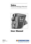
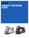
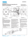
Images copyright Laser Devices, Inc. 2000
Super Power Point Trademark of Laser Devices, Inc.
2 Harris Court, Suite A-4
Monterey, CA 93940
U.S.A.
LASER LIGHT
Tel: (831) 373-0701
Fax: (831) 373-0903
E-mail: [email protected]
Internet: www.laserdevices.com
AVOID DIRECT
EYE EXPOSURE
OUTPUT 5mW
WAVELENGTH 632 - 650nM
CLASS IIIa LASER PRODUCT
Document P/N 1003
Rev. May 2005
USER’S MANUAL
Laser Aiming Device
ITAL AND OTAL
Super Power Point (635nM)
Infrared (835nM)
NSN 1005-99-535-5506
ITAL P/N19001(SPP)
ITAL P/N19002(IR)
OTAL P/N19101(SPP)
OTAL P/N19102(IR)
Made in the U.S.A.
U.S. Patent #5581898
Warranty
Warning Infrared Laser Light
Laser Devices, Inc. (LDI), offers a one-year limited warranty (excluding batteries
and light bulbs) from the date of original purchase against failure due to defect in
design, parts and workmanship. The warranty is void if the product serial number
has been removed or if the product has been misused, modified or abused. LDI
will replace defective products at its discretion. To the maximum extent permitted
by law, LDI disclaims all other warranties, whether expressed or implied, including
but not limited to implied warranties of merchantability and fitness for a particular
purpose. In no event shall LDI or its suppliers, distributors, dealers or agents be
liable for any damages whatsoever (including without limitation damages for
personal injury, wrongful death or pecuniary loss) arising out of the use or the
inability to use any LDI manufactured product. This limited warranty gives the
purchaser specific legal rights, which may vary by state and jurisdiction.
This aiming laser emits laser light that has been determined to pose a risk of
eye injury. In order to avoid the possibility of eye injuries resulting from direct
viewing, please adhere to the following warnings:
* Never look directly into the laser beam.
* Do not look directly at the laser light using scopes, binoculars
or night vision equipment.
* Avoid shining the laser onto mirrored surfaces.
* Observe all safety precautions with the laser that you would
observe with a loaded firearm.
* Avoid extended activation, especially in rain, mist, fog, smoke
or dusty conditions, as the laser beam can give away your
position to the enemy.
32
Accessories and Parts (cont'd)
-
+
30
LASER LIGHT
AVOID DIRECT
EYE EXPOSURE
OUTPUT 5mW
WAVELENGTH 632 - 650nM
CLASS IIIa LASER PRODUCT
1
General Information
Part #
1.5 Volt AA Battery
30115
Daytime Shooting Glasses, High Efficiency
Daytime Shooting Glasses, Standard Efficiency
30204
30203
Target "Accur-Aim LaserTM" with 3 Strips
Target Strips (35 Pieces)
30102
30143
Please read these handling and safety instructions and the instructions for your
weapon before attempting to install or use this laser aiming device. Failure to
comply with the installation instructions may result in damage to your weapon.
Safety First
Unload your firearm (remove the magazine and any cartridge in the chamber)
prior to mounting the laser on your weapon. Please familiarize yourself with the
location of the activation switch and pressure pad switch for the laser. Make
sure the laser and the firearm are pointed in a safe direction prior to attaching
the laser to the weapon.
! Activate the IR laser in a momentary fashion to avoid detection by enemy
forces equipped with night vision goggles.
! Using the IR laser in rain, fog and mist may increase the possibility that the3
enemy will detect your position.
Warning Infrared Laser Light
Laser and Firearm Safety
General Information
Safety First
Product Description
Laser Technical Data
Location of Major Parts
Installation of the Laser
Zeroing the Laser
Adjusting Windage/Elevation
Notes
Table of Contents
1
2
3
3
4
5
7
8-13
14-15
16-17
Operating Instructions
Operation Under Extreme Conditions
Replacement of Batteries
Removing the Laser
User Maintenance
Troubleshooting the Laser
Service & Repair
Accessories and Parts
Export Control
Warranty
18
19-20
21
22
23-24
25-26
27
28-30
31
32
Laser and Firearms Safety
Export Control
ALWAYS keep the gun and aiming laser pointed in a safe direction.
ALWAYS be sure the gun is safe to operate and the barrel is clear of any
obstruction.
ALWAYS know your target and what is beyond it.
ALWAYS wear eye and ear protection when shooting.
ALWAYS store your aiming laser, firearm and ammunition so they are secure
and not accessible to unauthorized persons.
ALWAYS treat every gun as if it were loaded.
NEVER direct an aiming laser at a mirrored surface.
NEVER look into an IR aiming laser to determine whether it is activated.
NEVER look directly into the laser light using night vision goggles, optical
scopes, telescopes or binoculars.
Purchaser agrees to abide by all laws and regulations relating to the sale of the
device, including any license required by the U.S. Department of State or U.S.
Department of Commerce prior to export. Purchaser also agrees to abide by all
laws, rules and regulations in effect in the jurisdiction where the product will be
used.
31
2
Product Description
Accessories and Parts (cont’d)
Momentary Pressure Switch Right Angle
Connector with 15 cm Connector
Momentary Pressure Switch Right Angle
Connector with 20 cm Connector
Momentary Pressure Switch Right Angle
Connector with 25 cm Connector
Momentary Pressure Switch Straight Connector
with 15 cm Connector
Momentary Pressure Switch Straight Connector
with 20 cm Connector
Momentary Pressure Switch Straight Connector
with 25 cm Connector
The ITAL and OTAL are compact, waterproof aiming devices manufactured to
meet the unique requirements of military special operations teams. The
systems are waterproof to 30 meters. The ITAL and OTAL systems mount on
any standard NATO 1913 rail. The low profile design is intended to mount in
front of most optical scopes. The lasers are fully adjustable for windage and
elevation for precise alignment at a variety of ranges.
The ITAL laser is in line with the center line of the barrel, and is used on flat
top rifles or when the laser is mounted in front of the front blade sight.
OTAL features an offset laser for use behind the front sight of the weapon.
6 Volt Tac/Light Assembly with 1” Ring
9 Volt Tac/Light Assembly with 1” Ring
70710
70712
70713
70711
70714
70715
21113
14155
29
4
Laser Technical Data
Accessories and Parts
Mounting Rails:
Picatinny/Weaver Mount for AK-47
Picatinny/Weaver Mount, Long (85.34mm) for 11.4mm to 19mm
Picatinny/Weaver Mount, Long (85.3mm) for 19mm to 25.4mm
Picatinny/Weaver Mount, Short (56.64mm) for 11.4mm to 19mm
Picatinny/Weaver Mount, Short (56.64mm) for 19mm to 25.4mm
LDI
Part #
24568
24449
24453
24447
24448
28
Troubleshooting the Laser (cont’d)
4. If laser is impossible to Zero, please check the following:
a. If the windage or elevation adjustment screw is at its maximum limit or is
getting difficult to turn, check that the mounting bracket is properly aligned
with the weapon barrel.
b. If the impact point appears to move, confirm that the mounting bracket is
firmly attached to the weapon. Also check to make sure that the laser is
firmly attached to the weapon so that it does not move under recoil forces. If
you suspect that the mount is moving, tighten the mounting screw. Also
tighten the thumb nut securing the laser to the mounting bracket using a
screwdriver or coin.
4. If the aiming laser still fails to operate, please contact LDI for assistance.
26
Laser Class
Optical Output
Beam Diameter
Range
Environment
Material
Color
Length
Width
Weight
Height
Battery
Battery Life
Lens
Diode Life
Class IIIb for infrared
3.5mw or less
0.58 cm2 at 25m
450m (visibility may depend on the generation of NVG)
Waterproof to 30 meters
Anodized aircraft aluminum 6061T-6
Flat black
8.12 cm
4.16 cm
140 grams (including battery)
2.82 cm without mount (3.75 cm with mount)
1.5 AA
5 hours continuous use
Coated glass lens
10,000 hours
Location of Major Parts (See Figure 1)
Item
1.
2.
3.
4.
5.
6.
7.
8.
9.
10.
11.
12.
13.
14.
15.
16.
17.
18.
19.
Description
Laser Housing
End Cover Assembly
Indicator Knob
Battery Cap Assembly
Optical Reducer Assembly
Windage and Elevation Assembly (x2)
Cable with Pressure Pad Assembly (see accessories for options)
1.5 Volt Alkaline Battery (optional Lithium battery, not shown)
Case Assembly Screws (Phillips head) (x2)
Crossbar Stud (Picatinny mount)
Compression Spring for Mount
Rail Crossbar Alignment Stud Short
Clamp for Weaver Base
Thumb Nut Knurled
Grommet for Battery Compartment
Battery Installation Label
Danger Label (not shown)
Front Cap Assembly
Battery Cap O-Ring
Installation of the Laser (cont'd)
If it is ever necessary to clean the LAD, rinse with fresh water and dry with a
clean cloth. If it is necessary to clean the front cap (Part #03159) blow dust or
debris off of the lens. If necessary, rinse the lens with fresh water and then use
lens paper, lens cleaner or a cotton swab to clean the lens. Do not use gun oil
or harsh chemicals to clean the front cap, as they may dissolve the silicone
seal and damage the laser.
Step 3. Installation of optional barrel mount
(Part No. 24447 or 24448).
Locate the position on the barrel where you
wish to locate the laser aiming device.
Attach the bottom brackets using the
supplied hex screws. Tighten the bottom
brackets firmly (see Figure 3).
Check the alignment of the NATO 1913 rail
to confirm that it is located in the correct
position. If necessary, loosen the mounting
screws and rotate the mounting rail into the
correct position.
Remove the battery to prevent the possibility of corrosion if the LAD is
going to be stored for an extended period of time (e.g., more than a week
or two).
24
Part No.
3491
A03458
021-1125
A03672
A04143
A03455
A03466
B30115
C01097
3282
0-109
3102
3101
3114
263
NA
NA
A03991
C00094
7
User Maintenance (cont'd)
If the battery needs to be replaced, see the section on battery replacement.
5
Figure 3
9
6
Service & Repair
This aiming laser was manufactured to provide years of rugged and
dependable use. In the event the laser ever needs internal repair, please
contact LDI or its European Service Center for a return authorization number.
Once you obtain the return authorization number, package the product securely
and return it postage paid to your service center. In the event the product is not
covered by the warranty, you will be notified as to the nature and the cost of the
necessary repair.
USA: Laser Devices, Inc
Europe: Technik Partner GmbH
2 Harris Court, A-4
Herrenlandstrasse 72
Monterey, CA 93940 USA
D-78315 Radolfzell, GERMANY
Tel: (831) 373-0701
Tel: (0049) 0 77 32 / 98 80 75
Fax: (831) 373-0903
Fax: (0049) 077 32 / 56 53 8
Email: [email protected]
Email: [email protected]
27
Figure 1
In the event the laser fails to operate or appears to operate at a low power,
please check the following prior to contacting the manufacturer for repair.
1. Fails to work. Confirm that the laser is a visible wavelength laser or use night
vision goggles to view the IR laser. If the appropriate night vision goggles are
being used, please check the following:
a. Replace the battery. See battery replacement instructions.
b. Check the battery installation to make sure the battery was installed with the
positive(+) terminal facing out of the laser assembly as shown in Figures 1 & 2.
2. Laser light is weak or dim.
a. Check the front cap and lens of the laser to make sure that it is not covered
with dirt or powder residue. If the front cap is dirty, clean gently with a cotton
swab or soft clean cloth taking care not to scratch the lens.
3. Clean the battery contact point on the battery cap to remove any corrosion.
Step 1. Confirm that your weapon is
unloaded.
Step 2. If the weapon does not have a
built-in NATO 1913 rail, install an
optional NATO 1913 rail (see Figure 2).
Suitable mounting locations include:
a. Above the barrel
b. Below the barrel
c. Behind the front sight (OTAL only)
d. Flat top rifle or on a built-in rail
adapter system
Troubleshooting the Laser
Installation of the Laser
8
25
Figure 2
The LAD does not require any particular maintenance when used under normal
conditions other than changing the battery and occasionally cleaning the unit.
Prior to use the user should check the following:
a. Test activation.
b. Make sure remote cable is attached.
c. Make sure the adaptor rail is firmly attached to weapon.
d. Confirm that the rail clamp is tight.
e. Check the sight alignment by test firing the weapon or by using the
manufacturer’s optional laser borelight (LDI Part #FA3160-635).
Step 4. Loosen the rail grabber knob so that the base will fit over the rail and
the crossbars fit the cutouts in the rail. Move the LAD forward or backward until
both crossbars are seated in a rail cutout (see Figure 4).
Step 5. Tighten the thumb screw until it is tight. Use a coin or a screwdriver to
firmly tighten so the LAD is securely mounted on the weapon.
Step 6. Plug the pressure pad switch remote cable into the connector port on
the back of the unit (see Figure 5). Rotate the locking ring on the presser pad
switch in a clockwise direction to lock the remote cable into place (see Figure 6).
Step 7. Locate the position on the foregrip for mounting the pressure pad
switch. Peel the backing off of the velcro and attach the pressure pad to your
weapon (see Figures 7 & 8).
User Maintenance
Installation of the Laser (cont'd)
23
10
Removing the Laser
Step 1. Confirm that your weapon is
unloaded.
Step 2. Loosen the rail clamp knob.
Use a screwdriver if necessary.
Remove the laser from the rail. If the
laser is going to be stored for a
period of time, remove the batteries.
Step 3. Remove optional NATO 1913
rail if necessary.
Figure 12
22
Figure 4
Figure 5
11
Operation Under Extreme Conditions (cont’d)
Dust and Sand Storms: Minimize activation of the LAD, as the laser light may
give away your position. Keep laser stored in pack unless needed. If necessary,
clean laser front cap as described in maintenance section.
High Altitude Operation. No special procedures required.
To clear dry dust or sand from the front cap, blow the dirt off the lens. If the
lens mists up or becomes wet, use a clean cloth, lens cleaner or lens paper
to clean the front cap.
Figure 7
Figure 8
20
Operating Instructions
Once the laser has been properly mounted on the weapon and properly adjusted
for windage and elevation, the LAD is ready to use. Prepare the LAD for
operation by turning the rotary switch from the OFF position to the ON/
Momentary position. In combat or when on patrol, operate the laser using the
Momentary remote switch. REMEMBER, NIGHT VISION EQUIPMENT IS
REQUIRED TO VIEW THE IR LASER POINT ON THE TARGET. If you
accidentally activate the IR laser, you may reveal your position to opposing
forces using night vision equipment.
Avoid prolonged activation of the aiming laser in mist, fog, smoke, dust, high
humidity, snow or rain conditions, as the laser beam may reveal your
position to the opposing forces.
When the laser is not being used, remember to turn the rotary switch back to the
OFF position to prevent accidental activation. If the laser is to be stored for a long
period, remove the batteries.
18
13
Zeroing the Laser (cont’d)
Step 3. Confirm that your weapon is unloaded.
Step 4. Adjust the windage or elevation by turning the windage or elevation
knob by no more than one-quarter (1/4) turn. Windage: Turning the windage
knob clockwise will move the laser point to the right, and turning the knob
counter-clockwise will move it to the left. Elevation: Turning the elevation
knob clockwise will move the laser point down, and turning it counterclockwise will move it up. Always move the laser point towards the bullet
holes on the target
Step 5. Test fire the weapon again to check the new alignment. If necessary,
repeat the alignment process from Step 1. above.
15
Installation of the Laser (cont'd)
Step 8. Attach the remote cable
retainer clip to the wire. Peel the
backing off and attach to the foregrip.
Step 9. Test the laser for proper
operation by turning the rotary switch
into the Momentary position and
depress the pressure pad switch. Use
night vision goggles to view the laser
point on the target.
Step 10. Zero the unit for windage
and elevation (see section on Zeroing
the Laser).
12
Figure 6
Replacement of Batteries
ITAL and OTAL use a single AA battery that will provide about 5 hours of
continuous operation depending on temperature. When the laser light dims the
battery needs to be changed. Follow the steps below to replace the battery.
Step 1. Confirm that your weapon is unloaded.
Step 2. Remove the battery cap on the front of the unit (turn counter-clockwise).
Step 3. Remove the depleted battery. If necessary, remove the laser from the
weapon.
Step 4. Reinstall the new battery with the negative (-) terminal facing out of the
housing (see Figures 1 & 12).
Step 5. Screw the battery cap back on to the laser housing. Test the laser to
confirm proper battery installation. (Use night vision goggles to view the IR
beam). If the laser was removed from the mount, confirm that the laser point is
still properly aligned for windage and elevation.
21
Extreme Heat. No special procedures required.
Extreme Cold. Extreme cold will reduce battery life. For use in temperatures
below -20oC or -5oF store alkaline batteries in an inner pocket. For operation in
extremely low temperatures use optional lithium AA batteries.
Salt Air. No special procedures required.
Water, Mud, Snow. Confirm that the battery cap is firmly tightened. If the front
cap has been loosened or replaced, confirm that it is also tight. Use the switch
connector plug to seal the switch opening. Clean the LAD after use with fresh
water and wipe dry with a clean cloth. If LAD front cap requires cleaning, see
the section on user maintenance.
In order to precisely align the laser to your weapon or to change the alignment for
use at other distances, follow the steps below:
Operation Under Extreme Conditions
Zeroing the Laser
Step 1. Aim the weapon using the laser aiming device at the target using a
sandbag or steady rest. Place the laser point on the center of the target and
carefully fire three rounds from the weapon and check the target for the impact
point. Use night vision goggles to view the IR laser point.
Step 2. If the bullet holes are clustered to one side or the other, then you will
need to adjust the windage (see Figure 9 & 10). If the bullet holes are grouped
above or below the target, then you will need to adjust the elevation (see Figure
11).
14
19
Adjusting Windage/Elevation
Always adjust the windage and elevation knobs in one-quarter (1/4) turn
increments or less. Move the laser towards the bullet holes in the target.
Do not overadjust the windage or elevation, as it may damage the laser.
Laser Point
of Aim
Bullet Holes
Point of
Impact
Move Laser Down
Use Elevation
Laser Point
of Aim
Bullet Holes
Point of
Impact
Move Laser to Right
Use Windage
Figure 10
Figure 11
Figure 9
16
17