1
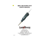
MBS-1A PREALIGNED
BORELIGHT
USER'S MANUAL
Manufactured by
Laser Devices Inc.
2 Harris Court, Suite A-4
Monterey, CA 93940 U.S.A
Tel: (831) 373-0701 Fax: (831) 373-0903
E-mail: [email protected]
www.laserdevices.com
4/1/00
Warning: Laser Light
The MBS-1A borelight when activated emits a laser
light that has been determined to pose a risk of eye
injury. In order to avoid the possibility of injury, please
adhere to the following warnings:
* Avoid looking directly into the laser beam.
* Do not look directly at the laser light using
scopes or binoculars.
* Avoid shining the laser onto mirrored surfaces.
* Do not direct the laser into the eyes or face of
persons or animals.
* Observe all safety precautions with the laser
that you would observe with a loaded firearm.
LASER LIGHT
AVOID DIRECT
EYE EXPOSURE
OUTPUT 5mW
WAVELENGTH 632 - 650nM
CLASS IIIa LASER PRODUCT
WARRANTY INFORMATION
Laser Devices, Inc. (LDI) offers a one-year limited
warranty from the date of original purchase against
failure due to defect in design, parts and workmanship
(normal wear and tear excluded). The warranty does
not cover batteries and the plastic alignment inserts.
The warranty is void if the product serial number has
been removed or in the event the product has been
misused, modified or neglected. LDI will replace
defective products at its discretion. To the
maximum extent permitted by law LDI disclaims
all other warranties whether expressed or implied,
including but not limited to implied warranties of
merchantability and fitness for a particular
purpose. In no event shall LDI or its suppliers,
distributors, dealers or agents be liable for any
damages whatsoever (including without limitation
damages for personal injury, wrongful death or
pecuniary loss) arising out of the use or the
inability to use any LDI manufactured product.
This limited warranty gives the purchaser specific
legal rights, which may vary from state to state or
jurisdiction to jurisdiction.
20
Rules for Safe Use
of the MBS-1A
ALWAYS use the factory supplied inserts and insert
retaining screw.
ALWAYS when trueing the MBS-1A in the bore of
the weapon turn the device in a clockwise
direction.
ALWAYS when finished boresighting the weapon
make sure that the insert and the retainer
screw did not become detached in the
barrel of the weapon.
ALWAYS remove the borelight from the weapon as
soon as you have finished aligning the
sight.
ALWAYS take your weapon to the range and test
fire it to confirm proper sight alignment
after using the borelight.
ALWAYS assume that the sight alignment calculated
using the borelight is only an approximation of the actual impact point where a
bullet will strike the target.
NEVER boresight a loaded gun.
1
Rules of Firearms Safety
ALWAYS keep the gun pointed in a safe direction.
ALWAYS keep your finger off the trigger until ready
to shoot.
ALWAYS keep the gun unloaded until ready to use.
ALWAYS be sure the gun is safe to operate and the
barrel is clear of any obstruction.
ALWAYS use the proper factory made ammunition
for your particular gun.
ALWAYS know your target and what is beyond it.
ALWAYS wear eye and ear protection when
shooting.
ALWAYS store guns and ammunition in separate
locked containers so they are secure and
not accessible to children or unauthorized
persons.
ALWAYS treat every gun as if it were loaded.
NEVER use alcohol or drugs before or during
handling a gun.
CHAPTER 4
TROUBLESHOOTING
Section 4.1. Unit Fails to Operate
1. Fails to operate.
a. Replace the battery (see instructions).
b. Check the battery installation to make sure
the batteries were installed with the positive
(+) terminal facing out.
2. Laser light is weak or dim.
a. Replace the battery (see instructions).
b. Check the front cap and lens of the laser to
make sure that it is not covered with dirt. If the
front cap is dirty, clean gently with a cotton
swab or soft clean cloth taking care not to
scratch the lens.
3. If the borelight still fails to operate, please
contact the manufacturer for assistance. See
Service and Repair, Section 4.2
Section 4.2. Service and Repair
The borelight produt is manufactured to provide
years of rugged and dependable use. In the
event the borelight ever needs to be repaired,
please contact Laser Devices, Inc. directly for a
return authorization number. Once you obtain the
return authorization number, package the product
securely and return it postage paid to LDI. In the
event the product is not covered by the warranty,
you will be notified as to the nature and the cost
of the necessary repair.
LASER DEVICES, INC.
2 Harris Court, Suite A-4
Monterey, CA 93940 U.S.A.
Tel.: (831) 373-0701
Fax: (831) 373-0903
Internet: www.laserdevices.com
2
19
CHAPTER 1
INTRODUCTION
6. Mark the OFFSET DISTANCE below the center
point marked on the target.
7. Adjust your weapon sight to the OFFSET
POINT you have marked on the target.
8. Take your weapon to the range and test fire it to
confirm the alignment of the sight.
DANGER: Ballistics tables may be wrong!
Errors may have crept into the published data.
In addition, it should be kept in mind that
ballistic performance is dependent on the
characteristics of each barrel, air temperature,
humidity, elevation, and a variety of other
factors. In addition, a very small misalignment
of the borelight may move the actual impact
point several inches. As such, the offset point
derived herein should always be considered
an approximation. Hence, the trajectories
provided herein and the information presented
by any other source should be considered, at
best, an approximation.
USAGE
Please read this instruction manual before you
attempt to use the MBS-1A borelight. While
reading the manual pay special attention to items
in bold text addressing WARNINGS and
possible DANGERS associated with the
improper use of the borelight product.
PRODUCT DESCRIPTION
The MBS-1A is a precision laser instrument used to
provide a quick check for the alignment of optical
scopes, open sights and laser aiming devices. This
manual contains instructions relating to the operation,
maintenance and troubleshooting of the MBS-1A.
1-1 GENERAL INFORMATION
A. Model Number and Equipment Name
Laser Borelight, Model MBS-1A
B. Contact Information for the Manufacturer
Laser Devices, Inc.
2 Harris Court, Suite A-4
Monterey, CA 93940 U.S.A.
Tel: (831) 373-0701
Fax: (831) 373-0903
E-mail: [email protected]
www.laserdevices.com
18
3
SECTION 1-2 GLOSSARY
Aiming Point
The exact point on the target
that you wish to hit.
Axis of the Barrel
A straight line from the center of
the weapon barrel to the target.
Bore
The inside of the weapon barrel.
Bore Rod
A part of the borelight that fits
into the bore of the weapon.
Danger
Conditions or procedures that
must be observed to avoid the
risk of serious injury or death.
Elevation
Vertical (up/down) movement of
a sight.
Insert
The plastic part used to configure the borelight for aligning
different calibers of weapons.
5. Assuming that you will boresight the .308 Cal.
rifle firing the bullet described in the table at 50
yards, the offset point to be marked on the
boresight target is calculated as follows:
a. add the True Bullet Drop of .49 inches; and
b. the Expected Trajectory Height above the
line of sight at 50 meters from the ballistics
table for the range at which you want to align
your weapon sight. This height according to the
ballistics table is 1.56 inches. See Figure 3-7 &
3-8.
Total Offset Distance
Sight to be zeroed for accuracy at 300 yards
Target at 50 Yards
Insert Retainer Screw The screw part used to attach
the insert to the bore rod.
Horizontal (left/right) movement
adjustment of a sight.
Warning
Conditions or procedures that
must be observed to avoid
damage to equipment or risk of
injury to persons.
Zero Point
The point on the target where
the bullet will hit if the sight has
been properly adjusted.
Offset distance
Laser beam path from borelight
ON
Windage
2.05"
FIGURE 3-7
Close-up of target at 50 yards
ls ½ inch
Each Square Equa
Line of sight through open sight
Laser beam
path from borelight
0.48" true bullet
drop @ 50 yards
Bullet path
1.5" est. trajectory
height over line
of sight @ 50 yards
FIGURE 3-8
4
17
Section 3.2. Calculating the Offset Distance
NOTE: Calculating the offset requires access to a
complete ballistics table or, better yet, a ballistics
calculator. In the alternative, you may want to
check out the offset calculator available on the
Internet at: http://wilson.simplenet.com/
shareware/borescope/index.html.
Remember, any offset point derived using a ballistics table or a ballistics calculator should be considered an approximation of the actual aim point.
1. Measure or calculate the distance between the
center of the bore and the center of the sight. For
example, if you are using an iron sight, then this
distance will be the distance from the center of
the bore to the top of the front post. A common
offset distance is 1.5 inches. See Figure 3-6.
Sight Offset
ON
FIGURE 3-6
2. Calculate the distance between the boresight
target and end of the weapon barrel. This distance
is usually not less than 10 yards and may be as
great as 50-100 yards, depending upon the scope
to be aligned and the visibility of the laser point.
3. Determine the distance to which you want to
align your weapon sight. This distance, for example, may be 200 yards or 300 yards.
SECTION 1-3 EQUIPMENT CHARACTERISTICS AND FEATURES
A. Characteristics of the Laser Borelight
The borelight operates by projecting a laser light
from the bore of the weapon to a target located at
a known distance from the barrel of the weapon
(usually 10 to 50 yards).
B. Features
! Battery powered using a standard 3 volt
lithium 123A battery.
! Easy twist-on and twist-off activation.
! Can be used in cold weather to -10°C or 0°F.
! Withstands high temperatures to +50°C or
123°F.
! May be stored without batteries at
temperatures between 40°C and 80°C.
! Can be used at high altitudes to 10,000 feet.
! Waterproof to 30 feet.
! Offers an estimated 7,500 alignment
activations before mean failure (not including
batteries and inserts).
! Laser prealigned by the manufacturer for
accuracy.
4. Use a ballistics table or a ballistics calculator for
the cartridge being used and determine the "actual
bullet drop" over the distance at which you want
to align your weapon sight. For example, the
ballistics table may indicate that a .308 Cal. Hollow
Point, Boat Tail Match King (Sierra) bullet will drop
19.75" over 300 yards. See sample table below.
16
5
SECTION 1-4 LOCATION AND DESCRIPTION
OF MAJOR COMPONENTS
Top View
Battery 123A
+
ON
Battery 3V
123A
A. Laser Aperture
(Avoid Eye Exposure)
-
C. Laser Housing MBS-1A
B. Switch Assembly
NOTE: Depending upon the distance from the
end of the barrel to the target that is being used
to align the weapon sight, the proper alignment
point for the weapon sight (i.e. the offset point)
may be above or below the imaginary straight
line drawn through the sight to the target. See
Figure 3-4.
Target at 5 Yards
ON
D. Boresight Rod Interface (Rifle)
ON
Line of sight through
sighting device
Laser beam path
D. Boresight Rod Interface (Pistol)
E. Insert Retainer Screw Only
Part #
F2949
F. Insert .22 CAL/.223/5.56mm
F2964
F. Insert .223 CAL/5.56mm OVERSIZE
F3170
F. Insert .270 CAL/7mm
F2965
F. Insert .30 CAL/.30-06/.308 CAL/7.62mm
F2966
F. Insert .38 CAL/.357 CAL/9mm
F2967
F. Insert .40 CAL/10mm
F2969
F. Insert .44 CAL/.45 CAL
F2970
F. Insert .50 CAL
F2974
Bullet path
FIGURE 3-4
4. The distance between the point on the target
where the laser point projected by the borelight
strikes the target and the point on the target to
where scope or sighting device needs to be
aligned so that a bullet fired from the weapon will
strike the aim point at a given range is the "Offset
Distance". See Figure 3-5.
Target at 5 Yards
(OPTIONAL)
Metal Spring Insert .22/.223/5.56mm
FA 03167
Offset distance
Figure 1-2
BORELIGHT ZERO AND ALIGNMENT TARGET
BORELIGHT ZERO AND ALIGNMENT TARGET
ON
FIGURE 3-5
Mark your offset on the target with a cross. Aim the at the cross
and adjust your sight's windage and elevation until the bore light
laser is centered on the circle in the center of the target.
Mark your offset on the target with a cross. Aim the at the cross
and adjust your sight's windage and elevation until the bore light
laser is centered on the circle in the center of the target.
G. Metric Alignment Target
G. Inch Alignment Target
6
15
CHAPTER 3
CALCULATING OFFSET FOR
SIGHT ALIGNMENT
Section 3.1. General Principles
1. The borelight, when properly aligned in the
weapon barrel, projects a laser point on the target
that is in line with the axis of the barrel. In other
words, the laser light travels in a straight line from
the barrel of the weapon to the target. See Figure
3-1 below.
Target at 50 Yards
Laser beam path from borelight
D U
ON
FIGURE 3-1
2. A bullet when fired from a weapon held
parallel with the ground immediately starts to
drop as soon as it leaves the barrel. The actual
rate of drop is determined in part by the velocity
of the bullet. Thus, the path of the bullet will
always be below the straight line of laser light
projected from the borelight. See Figure 3-2.
Target at 50 Yards
Laser beam path
from borelight
Bullet drop distance
Bullet path
SECTION 1-4 LOCATION AND DESCRIPTION
OF MAJOR COMPONENTS
A. Laser Aperture. The point where the laser light is
emitted. Avoid direct eye exposure to the laser
light projected from this aperture.
B. Switch Assembly. The borelight is activated by
tightening the Switch Assembly against the Housing.
C. Laser Housing. The body of the borelight that
contains the battery, windage and elevation
adjustments and the laser diode.
D. Bore Rod. The stainless steel rod used in conjunction with the appropriate barrel insert to center the
borelight in the barrel. The bore rod is supplied in
two lengths -- long for aligning rifles and short for
aligning pistols.
E. Insert Retainer Screw. This is the metal screw
assembly that is used to attach an insert to the bore
rod. DANGER: Never use the borelight without the
Insert Retainer Screw.
F. Inserts. The plastic parts affixed to the bore rod
with the Insert Retainer Screw. Each insert is sized to
fit a specific caliber of barrel.
G. Alignment Targets. Paper targets with metric or
U.S. units used for aligning the sight using the
borelight.
FIGURE 3-2
3. The optical scope or weapon sight is used to
cant the barrel in an upward direction so that a
bullet fired from the gun will trace an arc to the
target. An imaginary straight line drawn through a
properly aligned weapon sight attached to a
weapon will trace a descending line that crosses
the straight line from the bore of the weapon to
Target at 50 Yards
the target. See Figure 3-3.
Line of sight through open sight
Laser beam path from borelight
FIGURE 3-3
14
Bullet path
7
1-5 PRODUCT SPECIFICATIONS
NOTE: The borelight should remain on or very
close to the center of the target when the unit
is rotated in the barrel of the weapon.
7. If the laser point moves off of the center point
marked on the target, check to make sure the
borelight was properly inserted into the weapon.
Also check to make sure that the weapon is not
moving slightly as you rotate the borelight. If the
laser point continues to move off the center point,
you may have a bent barrel, bent bore rod or a
damaged Insert Retainer Screw. If the laser
point does not move from the Center Point,
then you may proceed to Section 2-2,
Boresighting Procedures.
Original laser
alignment point
Optimal
position of
laser point after
rotating borelight
by 90 degrees
FIGURE 2-6
8
13
Section 2-3 Alignment of the Borelight with
Target
1. Measure the range at which you intend to
boresight your weapon.
2. Mount the weapon to be aligned on a bench or
use sandbags to hold the weapon steady. The
weapon shall be mounted level or parallel to the
floor.
3. Activate the borelight by rotating the laser to the
ON position. Warning: Make sure the borelight
and weapon are pointed in a safe direction.
4. Place the boresight target down range at the
distance at which you intend to boresight your
weapon. This will usually be 10 to 25 yards.
5. Adjust the target position until the laser point is
directed to the Center Point of the target. The
Center Point and the target should be at the same
height as the borelight.
6. Rotate the borelight 90 degrees in a clockwise
direction. See Figure 2-4 below.
CHAPTER 2
OPERATING INSTRUCTIONS
Section 2-1 General
This chapter provides directions for the assembly
of the borelight, and insertion of the borelight into
the weapon.
Section 2-2 Assembly and Preparation for
Use
A. Installation of the Battery
1. Unscrew the Laser Housing from the Switch
Assembly.
2. Install the single 123A lithium battery in the
direction shown on the housing. Note: The
negative terminal is inserted into the Laser
Housing with the positive terminal facing the
Switch Assembly. See Figure 2-1 below.
BORELIGHT ZERO AND ALIGNMENT TARGET
Battery 123A
+
ON
Laser
alignment
point
Battery 3V
123A
-
E. Housing MBS-1A
D. Switch Assembly
FIGURE 2-1
Mark your offset on the target with a cross. Adjust
your sight's windage and elevation until aligned with
3. Reattach the Switch Assembly by tightening
the Laser Housing until the laser activates.
Note: While reattaching the Switch Housing,
make sure that the laser aperture is pointed in
a safe direction to avoid any possibility of
injury upon activation.
FIGURE 2-4
12
9
B. Installing the Insert
1. Select the appropriate insert for the weapon to
be aligned.
2. Slip the appropriately sized insert onto the
Insert Retainer Screw. The widest end of the
insert is slipped onto the Insert Retainer Screw
first. See Figure 2-2 below.
3. Install the Insert Retainer Screw by threading it
into the hole bored in the shaft of the bore rod.
Warning: Make sure not to cross-thread the
Insert Retainer Screw.
.223 Cal. Insert
Insert Retainer
Screw
Wide End of Insert
.45 Cal. Insert
FIGURE 2-2
D. Mounting the Borelight into the Weapon
Barrel
1. Confirm that the appropriately sized insert is
securely attached to the interface rod using the
Insert Retainer Screw.
2. Grasp the borelight and insert the bore rod
into the bore. Note: A properly sized insert
should offer a firm fit. If the insert cannot be
inserted into the barrel of the weapon with firm
pressure, then confirm that the appropriately
sized insert was installed on the bore rod.
Likewise, if the bore rod slips into the bore
without any pressure being applied, then the
insert may be too small.
3. Firmly press the bore rod into the barrel of the
weapon until the tapered or cone shaped area of
the bore rod contacts the bore.
WARNING: Apply force in a straight line with
axis of the barrel to avoid the possibility of
bending the bore rod or the Insert Retainer
Screw.
4. Once the Insert Retainer Screw is seated
against the bore rod use a cartridge case, coin,
screwdriver or knife blade to lightly tighten the
Insert Retainer Screw. See Figure 2-4 below.
DANGER: Failure to properly install the Insert
Retainer Screw on the bore rod may result in
the insert coming loose and lodging inside the
barrel of the weapon.
FIGURE 2-4
10
11