1
Cat. No. Z01E-EN-01
Cat. No. Z01E-EN-01
Smart Sensor ZFX Vision Sensor with built-in touch screen
SHORT MANUAL
Authorized Distributor:
Cat. No. Z01E-EN-01
Note: Specifications subject to change without notice.
Printed in Europe
Smart Sensor
ZFX
Vision Sensor with built-in
touch screen
SHORT MANUAL
Z01E-EN-01+ZFX+SettingGuide.book Seite 1 Mittwoch, 13. Februar 2008 2:38 14
ZFX
Vision Sensor
with built-in touch screen
Short Manual
Ver. 1.0, January 2008
Z01E-EN-01+ZFX+SettingGuide.book Seite 2 Mittwoch, 13. Februar 2008 2:38 14
Z01E-EN-01+ZFX+SettingGuide.book Seite 3 Mittwoch, 13. Februar 2008 2:38 14
TABLE OF CONTENTS
SECTION 1
Preparation . . . . . . . . . . . . . . . . . . . . . . . . . . . . . . . . . . . . . . .
5
1-1
System Overview. . . . . . . . . . . . . . . . . . . . . . . . . . . . . . . . . . . . . . . . . . . . . . . . . . . . . . . . . .
5
1-2
Connecting the Devices . . . . . . . . . . . . . . . . . . . . . . . . . . . . . . . . . . . . . . . . . . . . . . . . . . . . .
6
1-3
Installing the Controller. . . . . . . . . . . . . . . . . . . . . . . . . . . . . . . . . . . . . . . . . . . . . . . . . . . . .
8
1-4
Installing the Intelligent Cameras . . . . . . . . . . . . . . . . . . . . . . . . . . . . . . . . . . . . . . . . . . . . .
10
1-5
Installing the C-mount Cameras . . . . . . . . . . . . . . . . . . . . . . . . . . . . . . . . . . . . . . . . . . . . . .
12
1-6
Installing the External Lightings (Only For ZFX-SC50/SC90) . . . . . . . . . . . . . . . . . . . . . .
14
1-7
Installing the External Lightings (Only For C-mount Camera (ZFX-S/SC)) . . . . . . . . . . . .
15
SECTION 2
Main Operation. . . . . . . . . . . . . . . . . . . . . . . . . . . . . . . . . . . .
17
2-1
Operation Mode . . . . . . . . . . . . . . . . . . . . . . . . . . . . . . . . . . . . . . . . . . . . . . . . . . . . . . . . . . .
17
2-2
Adjusting the brightness of image . . . . . . . . . . . . . . . . . . . . . . . . . . . . . . . . . . . . . . . . . . . . .
18
2-3
Measurement Setting Example (Pattern Search) . . . . . . . . . . . . . . . . . . . . . . . . . . . . . . . . . .
20
2-4
Position Correction . . . . . . . . . . . . . . . . . . . . . . . . . . . . . . . . . . . . . . . . . . . . . . . . . . . . . . . .
22
2-5
Getting the clear image . . . . . . . . . . . . . . . . . . . . . . . . . . . . . . . . . . . . . . . . . . . . . . . . . . . . .
24
2-6
Changing the Display Information (ADJ/RUN Mode) . . . . . . . . . . . . . . . . . . . . . . . . . . . . .
30
2-7
Re-measuring the saved image (ADJ Mode). . . . . . . . . . . . . . . . . . . . . . . . . . . . . . . . . . . . .
31
SECTION 3
Run-Mode Measurement Process . . . . . . . . . . . . . . . . . . . . .
33
SECTION 4
Item Overview . . . . . . . . . . . . . . . . . . . . . . . . . . . . . . . . . . . . .
41
4-1
ITEM Overview (Pattern Search) . . . . . . . . . . . . . . . . . . . . . . . . . . . . . . . . . . . . . . . . . . . . .
41
4-2
ITEM Overview (Sensitive Search). . . . . . . . . . . . . . . . . . . . . . . . . . . . . . . . . . . . . . . . . . . .
43
4-3
ITEM Overview (Flexible Search) . . . . . . . . . . . . . . . . . . . . . . . . . . . . . . . . . . . . . . . . . . . .
44
4-4
ITEM Overview (Graphic Search) . . . . . . . . . . . . . . . . . . . . . . . . . . . . . . . . . . . . . . . . . . . .
45
4-5
ITEM overview (Area) . . . . . . . . . . . . . . . . . . . . . . . . . . . . . . . . . . . . . . . . . . . . . . . . . . . . .
46
4-6
ITEM Overview (Labeling). . . . . . . . . . . . . . . . . . . . . . . . . . . . . . . . . . . . . . . . . . . . . . . . . .
47
4-7
ITEM Overview (Position) . . . . . . . . . . . . . . . . . . . . . . . . . . . . . . . . . . . . . . . . . . . . . . . . . .
49
4-8
ITEM Overview (Width) . . . . . . . . . . . . . . . . . . . . . . . . . . . . . . . . . . . . . . . . . . . . . . . . . . . .
51
4-9
ITEM Overview (Count) . . . . . . . . . . . . . . . . . . . . . . . . . . . . . . . . . . . . . . . . . . . . . . . . . . . .
52
4-10 ITEM Overview (Angle) . . . . . . . . . . . . . . . . . . . . . . . . . . . . . . . . . . . . . . . . . . . . . . . . . . . .
53
4-11 ITEM Overview (Bright). . . . . . . . . . . . . . . . . . . . . . . . . . . . . . . . . . . . . . . . . . . . . . . . . . . .
54
4-12 ITEM Overview (HUE). . . . . . . . . . . . . . . . . . . . . . . . . . . . . . . . . . . . . . . . . . . . . . . . . . . . .
55
4-13 ITEM Overview (Defect) . . . . . . . . . . . . . . . . . . . . . . . . . . . . . . . . . . . . . . . . . . . . . . . . . . .
56
4-14 ITEM Overview (Grouping) . . . . . . . . . . . . . . . . . . . . . . . . . . . . . . . . . . . . . . . . . . . . . . . . .
58
3
Z01E-EN-01+ZFX+SettingGuide.book Seite 4 Mittwoch, 13. Februar 2008 2:38 14
SECTION 5
Appendices. . . . . . . . . . . . . . . . . . . . . . . . . . . . . . . . . . . . . . . .
4
59
5-1
What is decided by AUTO setting. . . . . . . . . . . . . . . . . . . . . . . . . . . . . . . . . . . . . . . . . . . . .
59
5-2
BANK and BANK-Group . . . . . . . . . . . . . . . . . . . . . . . . . . . . . . . . . . . . . . . . . . . . . . . . . . .
60
Revision History . . . . . . . . . . . . . . . . . . . . . . . . . . . . . . . . . . .
62
Z01E-EN-01+ZFX+SettingGuide.book Seite 5 Mittwoch, 13. Februar 2008 2:38 14
SECTION 1
Preparation
1-1
System Overview
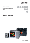
Basically, the ZFX-C is configured by the Controller and the camera.
Other external devices can be selected to be used in combination with the
ZFX-C according to the user’s specific requirements.
Cameras with lighting
Controller
ZFX-C10/15/20/25
(*5)
LCD monitor (option)
FZ-M08 (*2)
Monitor cable
FZ-VM
(cable built-in)
- Color camera
ZFX-SC10/SC50/SC50W
ZFX-SC90/SC90W
ZFX-SC150/SC150W
- Monochrome camera
ZFX-SR10/SR50
PC
1
2
3
4
SD Card (*4)
USB
Ethemet
Camera only
Touch pen
(*1)
Console
ZFX-KP
(*3)
RS-232C cable
ZFX-XPT_A
RS-422 cable
ZFX-XPT_B
- Color camera
ZFX-SC
- Monochrome camera
ZFX-S
A CCTV lens and light
source will be required.
Camera cable
PLC
Parallel I/O cable
ZFX-VP
ZFX-VS/VSR
*1. The Touch Pen (ZFX-TP) is supplied with the Controller.
*2. The same image as in the Controller's LCD monitor can be displayed in the
LCD monitor (option).
*3. The console can be used instead of the Controller's keys and menu buttons.
*4. Conforms to the SD Card “Physical layer specifications 1.01.”
File format: FAT16
*5. ZFX-C20/25b can be connected with 2 cameras.
5
Z01E-EN-01+ZFX+SettingGuide.book Seite 6 Mittwoch, 13. Februar 2008 2:38 14
1-2 Connecting the Devices
1-2
1-2-1
Preparation
Connecting the Devices
Connecting the Controller to the Power Supply
Use a power supply that meets the following specifications.
Item
Power supply voltage
Output current
Recommended power supply
Recommended electric wire size
Important
Specification
Approx. 24 VDC (21.6 to 26.4 VDC)
1.5 A min.
S8VS-06024 (24 VDC, 2.5 A)
0.14 to 1.5 mm² (max. 1 m)
Use a DC power supply with countermeasures against high voltages (safe
extra low-voltage circuits on the secondary side). If the system must meet UL
standards, use a UL class II power supply.
1. Loosen the two screws on the top of
the Power connector (male) using a
flat-blade screwdriver.
2. Insert the DC power terminal (wire)
into the Power connector (male) and
tighten the two screws on the top of
the Power connector to fasten the
power terminal with the screwdriver.
Tightening torque: 0.22 to 0.25 Nm.
3. Plug the Power connector (male) into
the Controller’s Power connector (female).
+
24 VDC
4. Tighten the two screws on the left and right of the Power connector (male)
with the screwdriver to fasten it. Tightening torque: 0.22 to 0.25 Nm.
1-2-2
Attaching Ferrite Cores
Attach ferrite cores (supplied) to both ends of the camera's cable and the
Controller's power cable, respectively.
Ferrite core
Ferrite core
Ferrite core
When attaching ferrite cores to the
Controller's power cable, pass the
cable once through each ferrite core.
+
6
-
DC power
supply
Z01E-EN-01+ZFX+SettingGuide.book Seite 7 Mittwoch, 13. Februar 2008 2:38 14
1-2 Connecting the Devices
1-2-3
Preparation
Connecting the Camera to the Controller
1. Insert the camera’s connector into the
Controller’s Camera connector.
2. Tighten the two fastening screws of the
Controller’s Camera connector.
Tightening torque: 0.15 Nm.
Important
Do not touch the terminals inside the connector.
Important
Fasten the connector while making sure that it is not subjected to vibration or
shock.
Important
Do not mount the Controller in such a way that a load is steadily applied on
the connector, for example, with tension applied to the cables.
Disconnection procedure
Loosen the fastening screws (two locations) to unlock the camera’s cable, and
then pull the camera’s cable connector straight out.
Important
Be sure to hold the connector of the camera to disconnect it. Failure to do so
may damage the camera’s cable.
Important
Do not touch the terminals inside the connector.
7
Z01E-EN-01+ZFX+SettingGuide.book Seite 8 Mittwoch, 13. Februar 2008 2:38 14
1-3 Installing the Controller
1-3
1-3-1
Preparation
Installing the Controller
Installation Precautions
To improve heat radiation, install the Controller only in the orientation show
below.
Upward
Right
Important
Wrong
Wrong
Install the Controller so that the distance between the Controller and other
devices is at least the dimensions shown in the figure below to improve the
ventilation.
When installing the Controller With the Exhaust Unit
attached:
When installing Controller only:
Min. 15 mm
Min.
50 mm
1-3-2
Min.
15 mm
Min.
50 mm
Important
Keep the ambient temperature less than 50 °C. If the ambient temperature is
higher than 50 °C, install a fan forced cooling system or an air conditioner to
keep the temperature lower than 50 °C.
Important
Avoid mounting on a panel, in which high-voltage emitting devices are
installed to prevent ZFX-C operation from being affected by noise.
Important
Allow at least 10 m between the Controller and power lines to keep noise at a
low level in the operating environment.
Installing on the DIN Track
1. Hook the Controller’s upper hook onto the
DIN track.
2. Push the Controller down onto the DIN track
until its lower hook is snapped into place.
1
2
Important
8
Attach the End Plate (sold separately) to both sides of the Controller on the
DIN track.
Z01E-EN-01+ZFX+SettingGuide.book Seite 9 Mittwoch, 13. Februar 2008 2:38 14
1-3 Installing the Controller
Important
Preparation
Attach the Exhaust Unit (supplied) to the Controller when installing other
devices adjacently on the same DIN track as the Controller.
End Plate (sold separately)
PFP-M
USB
OMRON
ZFX-C10
OUTPUT RUN
ERROR ENABLE
SD
CARD
MENU
ADJ
Exhaust Unit
RUN
AUTO
ESC
SET
1
2
3
4
PULL OPEN
DIN track (sold separately)
PFP-100N (1 m)
PFP-50N (0.5 m)
PFP-100N2 (1 m)
Removing procedure
1. Pull the Controller’s lower hook downwards.
2. Lift up the Controller from its bottom to remove it from the DIN track.
1
2
1-3-3
Mounting on the Panel
1. Install the long Panel Mount
Adapters on the four holes on the
Controller.
Panel mount adapters
Panel
1
2. Install the short Panel Mount
Adapters on the two holes on the
long Panel Mount Adapter.
3. Install the Controller with Mount
Adapters attached onto the panel
from the front.
3
2
2
1
4. Hook the hooks of the mounting
bracket onto the two holes (two
each at top and bottom) of the
longer Mount Adapters and tighten the screws.
Tightening torque: 1.2 N•m.
4
5. Make sure that the Controller is
firmly fixed on the panel.
Mounting bracket
9
Z01E-EN-01+ZFX+SettingGuide.book Seite 10 Mittwoch, 13. Februar 2008 2:38 14
1-4 Installing the Intelligent Cameras
1-4
1-4-1
Preparation
Installing the Intelligent Cameras
Optical chart
ZFX-SC10/SR10
Setting distance L (mm)
60
49
Setting distance (L)
50
34
0
4
10
4.9
Detection range (H)
ZFX-SR50
8.9
Detection range H (mm)
ZFX-SC50/SC50W
Setting distance L (mm)
Setting distance L (mm)
300
187
190
194
100
100
38
30
9
9.8
60
31 30
49
9.8
Detection range H (mm)
ZFX-SC90/SC90W
ZFX-SC150/SC150W
Setting distance L (mm)
Setting distance L (mm)
160
49
Detection range H (mm)
240
227
142
180
100
67
115
40
40
70
49
100
89
Detection range H (mm)
100
80
120
89
160
148
Detection range H (mm)
Note • The lens has a fixed focal point. The actual detection range and focal point
vary from lens to lens, so adjust the distance to the measurement target
after replacing the lens or camera.
• The camera mounting distance listed in the following tables is an approximate value. Mount the Camera so that the distance to the measurement
target can be adjusted easily.
• If the object size and detection range are incompatible, use a combination
of a camera (without lighting), standard CCTV lens and light source.
10
Z01E-EN-01+ZFX+SettingGuide.book Seite 11 Mittwoch, 13. Februar 2008 2:38 14
1-4 Installing the Intelligent Cameras
1-4-2
Preparation
Installing the mounting fixture
The mounting fixture can be installed on all of the four mounting surfaces.
1. Align the two hooks on one side of
the mounting fixture with the two
grooves on the camera body.
2. Push the other hook down until it
is snapped into place.
Make sure that the mounting fixture is firmly fixed on the camera.
Hooks
Mounting
fixture
Grooves on camera
3. Fasten the mounting fixture at the
mounting location with screws.
Tightening torque
M4: 1.2 Nm
1/4”-20 UNC: 2.6 Nm
Removal procedure
1. Insert a screwdriver into the gap
(one of the two gaps) between the
mounting fixture and the camera
case, and remove the mounting
fixture.
Mounting fixture
1-4-3
Adjusting the camera focus
1. Adjust the distance between the
camera and the measurement target and fasten the camera.
Refer to the optical chart and set
the camera in a position so that
the area to be checked is within
the detection area (LCD monitor).
“Optical chart” p. 10.
Setting distance (L)
Detection range (H)
2. Turn the focus adjustment control
to the left and right to adjust the
focus.
Focus
adjustment
control
Note First turn the focus adjustment control slightly to the left and right, to make
sure that the Focus adjustment control is not at the upper or lower limit positions. Do not exert unnecessary force to turn the control at the upper or lower
limit positions as this might damage the control.
(For ZFX-SC90_/SC150_, the control stops turning at the nearest position. It
turns free at the farthest position.)
11
Z01E-EN-01+ZFX+SettingGuide.book Seite 12 Mittwoch, 13. Februar 2008 2:38 14
1-5 Installing the C-mount Cameras
1-5
1-5-1
Preparation
Installing the C-mount Cameras
Optical chart
The values in the following chart are approximations, and the Camera must be
adjusted after it is mounted.
Camera distance A(mm)
Lens model
3Z4S-LE
ML-5018
10000
ML-3519
ML-2514
ML-1614
ML-1214
1000
ML-0813
ML-0614
t: Extension tube
100
40
4
10
100
1000
Detection range(mm)
Example
t0: Extension tube
is not required.
t5: 5-mm extension
tube is required.
Lens model
3Z4S-LE
Camera distance A(mm)
ML-10035
10000
ML-7527
t0
t2
t0
t5
t10
t40 t35 t30 t25
t45
t50
t60
1000
t20 t15
t2
t5
t50
200
2
t45 t40t35t30
t15
t25 t20
10
t10
100
1000
Detection range(mm)
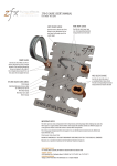
The X axis of the optical chart shows detection range L (mm), and the Y axis
shows the camera distance A (mm). The curves on the optical chart show the
relationship between the detection range and camera distance for each CCTV
lens. The values are significantly different for each lens, so double-check the
model of the lens before using the graph. The “t” values indicate the lengths of
the Extension Tubes. The value “t0” shows the case where an Extension Tube
12
Z01E-EN-01+ZFX+SettingGuide.book Seite 13 Mittwoch, 13. Februar 2008 2:38 14
1-5 Installing the C-mount Cameras
Preparation
is not required and the value “t5.0” shows the case where a 5-mm Extension
Tube is used.
Example
When a 3Z4S-LE ML-5018 CCTV Lens is being used and a detection range of
40 mm is required at the measurement target, a camera distance of 500 mm
and 5-mm Extension Tube are required.
Camera
Extension Tube t_ (mm)
Lens
Camera distance A (mm)
Measurement object
Detection range L (mm)
1-5-2
Installing the Camera Mounting Base
The camera mounting base mounted on the bottom of the camera can be
installed on all of the four mounting surfaces. To change the mounting surface,
remove the three mounting screws (M2 x 6) from the camera.
Camera Mounting Base
• Tightening torque when fastening the camera mounting base at the
mounting location
M4: 1.2 Nm
1/4”-20 UNC: 2.6 Nm
13
Z01E-EN-01+ZFX+SettingGuide.book Seite 14 Mittwoch, 13. Februar 2008 2:38 14
1-6 Installing the External Lightings (Only For ZFX-SC50/SC90)
1-6
1-6-1
Preparation
Installing the External Lightings (Only For ZFX-SC50/SC90)
Connecting the Optional Lighting to the Camera
The optional lighting can be mounted to the rear connector of the camera
(ZFX-SC50_/SC90_) with a single motion. Since the power is supplied from
the camera side, no power supply is required for the optional lighting.
Remove the cap from the optional lighting connector on the rear of the camera.
Connector of the
optional lighting
ZFX-SC50
ZFX-SC90
Optional lighting can be used
with these two Cameras.
Bar Lighting
ZFV-LTL01
14
Double Bar Lighting
ZFV-LTL02
Low-angle Bar Lighting
ZFV-LTL04
Through-beam Lighting
ZFV-LTF01
Z01E-EN-01+ZFX+SettingGuide.book Seite 15 Mittwoch, 13. Februar 2008 2:38 14
1-7 Installing the External Lightings (Only For C-mount Camera (ZFX-S/SC))
1-7
1-7-1
Preparation
Installing the External Lightings (Only For C-mount Camera (ZFX-S/SC))
Connecting the Optional Lighting to the camera
The optional lighting can be connected to the Strobe Controller. And the
Strobe Controller can be connected to the camera (ZFX-S/SC). No power
supply is required for the optional lighting.
Strobe Controller
Strobe Controller
3Z4S-LT MLEK-C100E1TSX
External Lighting
3Z4S-LT Series
The lighting that current consumption is 1.0A or less can be connected
15
Z01E-EN-01+ZFX+SettingGuide.book Seite 16 Mittwoch, 13. Februar 2008 2:38 14
1-7 Installing the External Lightings (Only For C-mount Camera (ZFX-S/SC))
16
Preparation
Z01E-EN-01+ZFX+SettingGuide.book Seite 17 Mittwoch, 13. Februar 2008 2:38 14
SECTION 2
Main Operation
2-1
Operation Mode
ADJ
MENU
RUN
Mode switch
Mode
MENU mode
The ZFX-C has the following three
modes. Switch to the desired mode
before you start operation. To switch
the operation mode, use the mode
switch.
Description
This mode is for setting the
measurement conditions.
The easy-to-follow iconbased display allows operations to be performed intuitively.
This mode is for checking
the measurement status and
adjusting conditions. Measurement results are only
displayed on the monitor and
are not output.
Important
Trigger input isn’t acceptable
Top menu
LIVE
TEA
Bank
Tool
ADJ mode
Top Screen
This mode is used for performing actual measurement. Measurement results
are displayed on the monitor and output.
Important
Measurement trigger by
menu operation is to push
[SET]-key & [UP]-key
System
Save
Top Screen
OK
Individual result
353ms
Camera 0
0.Bank00
0.Pattern Search
Judge
Correlation
Position X
Position Y
Angle
OK
92
462
352
15
Previous
RUN mode
Setup
TE
A
Next
Dsplay SW
Adjust
Top Screen
OK
Individual result
353ms
Camera 0
0.Bank00
0.Pattern Search
Judge
Correlation
Position X
Position Y
Angle
Previous
OK
92
462
352
15
Next
TE
A
Dsplay SW
Capture
17
Z01E-EN-01+ZFX+SettingGuide.book Seite 18 Mittwoch, 13. Februar 2008 2:38 14
2-2 Adjusting the brightness of image
2-2
2-2-1
Main Operation
Adjusting the brightness of image
Lighting Intensity (Only the intelligent Cameras)
MENU mode - [Setup] - [Cameras] - [Light Control]
SD
Light Control
A
D
B
How blocks are displayed
TEA
C
Top surface (surface printed with model No.)
A
View from
this side
5 5 5 5
ALL A B C D
Apply
Auto
Cancel
D
B
Capture
C
1. Push
"Auto"
The thumbnails of images automatically captured
under differen illumination patterns are displayed
SD
Light Control
TEA
TEA
TEA
TEA
TEA
TEA
TEA
TEA
TEA
TEA
TEA
2. Select the image
Apply
Cancel
SD
Light Control
Capture
A
3. Push "Apply"
D
B
The lighting condition of the
selected image is displayed
4. Fine-adjust these conditions as required.
TEA
C
2 3 2 3
ALL A B C D
Auto
Apply
Cancel
Amount of emitted light
Important
If the workpiece is glossy, install the
camera at an angle to prevent mirror
reflection light from being picked up by
the camera.
Mirror reflection light
18
Capture
Z01E-EN-01+ZFX+SettingGuide.book Seite 19 Mittwoch, 13. Februar 2008 2:38 14
2-2 Adjusting the brightness of image
2-2-2
Main Operation
Shutter Speed
Set the shutter speed to match the speed of movement of the measurement
target and the lighting environment.
MENU mode - [Setup] - [Cameras] - [Shutter Speed]
Setting value
1/170 to 1/20000 s
Description
Fixes the shutter speed to the desired value. Only available
candidate shutter speeds are displayed. The candidates differ with the camera that is connected and setup conditions.
Note Guidelines for setting shutter speed
Shutter speed characteristics are as follows. Select the appropriate shutter
speed to suit your inspection requirements.
Shutter Speed
1/170 s
•
1/20000 s
2-2-3
Speed of Movement of Measurement Target
Slow
•
Fast
Gain Setting
The sensor's gain (sensitivity) can be adjusted if bright images cannot be
obtained just by the Shutter Speed and Light Control settings.
MENU mode - [Setup] - [Cameras] - [Gain]
Setting value
x 1.0, x 1.5, x 2.0
Description
Sets the gain factor.
x 1.0: The gain factor is not changed. (default value)
x 1.5: The gain factor is set to 1.5X.
x 2.0: The gain factor is set to 2.0X.
Note Guidelines for setting gain
Increasing the gains results in a brighter image, however, the noise component contained in the image also becomes more conspicuous. Select the
appropriate gain factor to suit your inspection requirements.
Gain
x 1.0
•
x 2.0
Image
Dark
↑ ↓
Bright
Image Quality
Good (little noise)
↑ ↓
Coarse (conspicuous noise)
19
Z01E-EN-01+ZFX+SettingGuide.book Seite 20 Mittwoch, 13. Februar 2008 2:38 14
2-3 Measurement Setting Example (Pattern Search)
2-3
Main Operation
Measurement Setting Example (Pattern Search)
OK
NG
Select the item (Pattern Search)
ADJ
MENU
1. Switch to the MENU mode.
RUN
Mode switch
2. Select the [Setup] icon.
Top menu
LIVE
TEA
Tool
3. Select the measurement item icon.
(Pattern Search)
Bank
Setup
System
Save
Shape
Size
Pattern
Sensiti.
Edge
Bright&Color
Application
Cameras
Register
Item
Position
Add func
Register the image of non-defective product as a model image (standard
for measurement)
4. Select the [Register model]
Register model
Reference model
TEA
Search region
Reference point
Inspect
Img Adj
Region
Detail
Limits
5. Select the shape of model region
Box
Circle
Elipse
TEA
Circum Polygon
Inspect
20
Img Adj
Region
Detail
Limits
Z01E-EN-01+ZFX+SettingGuide.book Seite 21 Mittwoch, 13. Februar 2008 2:38 14
2-3 Measurement Setting Example (Pattern Search)
Main Operation
6. Enclose the model region
[130,140]
Move
New
• First, move the region
• Next, select [Size] and change the
region
TEA
• Finally, select the [Apply]
Size
Apply
Cancel
Set the parameter automatically
7. Select [AUTO]
(key or icon on screen)
The best color filter is selected and
model is registered.
AUTO
ESC
AUTO key
SET
Register model
Reference model
TEA
Search region
Reference point
Img Adj
Region
Detail
Limits
Auto
Check the measurement status by measuring some samples
8. Switch to ADJ-mode
ADJ
MENU
RUN
Mode switch
Key point
• If sample object is moved, is the
measurement stable ?
OK
Individual result
353ms
Camera 0
0.Bank00
0.Pattern Search
• Is there the definite difference of
correlation between OK sample
and NG sample ?
Judge
Correlation
Position X
Position Y
Angle
OK
92
462
352
15
Previous
TE
A
Next
Dsplay SW
Adjust
Change the limits (thresholds) of correlation, if needed.
9. Select the [Adjust]
Previous
Next
Display sw
Adjust
10. Select the [Limits]
Img Adj
Limits
Region
11. Change the limits.
L Limit
Defect
samples
H Limit
Non-defect
samples
85
L:
100 H:
100
Correlation
0
100
21
Z01E-EN-01+ZFX+SettingGuide.book Seite 22 Mittwoch, 13. Februar 2008 2:38 14
2-4 Position Correction
2-4
Main Operation
Position Correction
This function is used when the position or orientation of measurement target
is no fixed. If you use this function, the amount of the shift from the reference
position iscalculated, and the position of the measurement region is corrected
before measurement is performed.
TEACH process
of Position Correction
Image input
TEACH process
of measurement Item
TEACH
process
Measuring the
area of grey part
Image input
Position Correction
Measurement
Inspection
With Position
Correction
“Position Correction” fixes the
position of measurement region.
“Position Correction” recognizes
the amount of the position shift.
Important
Use a saved image, when setting the position correction.
If you use an image different from the one that was initially used for position
correction, position correction might not be set correctly. Moreover, set the
measurement items again, if you use a different image.
Recommended procedural
Registering the live image
MENU mode - [Setup] - [Register] - [Image 0] - [Register image] - [Live image]
Position correction
0.Pattern
SD
Region
Push [Image SW]. After that, the
image which is used for position
correction is switched.
Register model
Reference model
TEA
Search region
Reference point
Inspect
Img Adj
Region
Image sw
Detail
Setup menu
Limits
Capture
Saving the image into SD card
MENU mode - [Setup] - [Register] - [Image 0] - [Save to SD card]
--> In case that you need to adjust the position correction, you can use the same
image in SD card.
22
Z01E-EN-01+ZFX+SettingGuide.book Seite 23 Mittwoch, 13. Februar 2008 2:38 14
2-4 Position Correction
Main Operation
Edge Position
Density changes.
Measurement
target is not
at an angle.
The position is detected by density changes and is
corrected.
How to set is the same way of "Position"
Labeling
Image can be binarized.
The image is binarized to detect the group (label) of
the measurement target color to correct the
position.
How to set is the same way of "Labeling"
1 model
If the measurement target has a characteristic
pattern, the position of that pattern is detected to
correct the position.
Measurement target has
a characteristic pattern.
How to set is the same way of "Pattern Search"
2 model
Two models are registered, and the position
difference is corrected using the center coordinates
of a straight line joining the two models and the angle
of that line to the horizontal.
High accuracy correction
is needed.
How to set is the same way of "Pattern Search"
Area
Measurement
target is at
an angle.
The image is binarized to detect the position of the
measurement target color area to correct the
position.
Image can be binarized.
How to set is the same way of "Area"
Angle
Two positions are detected by density changes, and
position difference is corrected using the center
coordinates of a straight line joining these two
positions.
Density changes.
How to set is the same way of "Angle"
Graphic Search
Uneven density
The position of the pattern is detected and corrected
using profile information. Measurement can be
performed stably even when density is uneven.
How to set is the same way of "Graphic Search"
23
Z01E-EN-01+ZFX+SettingGuide.book Seite 24 Mittwoch, 13. Februar 2008 2:38 14
2-5 Getting the clear image
2-5
2-5-1
Main Operation
Getting the clear image
Color Filter
What is the color filter?
This function improves the contrast of images.
Normally “AUTO” function can selects the best color filter. But if needed, you
can select the best filter in typical color or any custom color. This function can
be set only when a color camera is connected to the controller.
Regular monochrome
image conversion
Low contrast image
Color filter
Contrast is improved!
Red
(AUTO)
Magenta
Yellow
(AUTO)
(AUTO)
Gray
(AUTO)
Blue
Green
(AUTO)
(AUTO)
{
AUTO:
Automatically the best color filter is selected.
SELECT: You can choose from typical 7 colors.
SELECT - CUSTOM: You can select any color from
the color bar.
Cyan
(AUTO)
Color filter is available in the below items.
• (Shape) Pattern Search
• (Shape) Sensitive Search
• (Shape) Flexible Search (only C20/25)
• (Shape) Graphic Search (only C20/25)
• (Edge) Position
• (Edge) Width
• (Edge) Count
• (Edge) Angle
• (Bright&Color) Bright
• (Application) Defect
• (Application) Grouping (only C20/25)
24
Z01E-EN-01+ZFX+SettingGuide.book Seite 25 Mittwoch, 13. Februar 2008 2:38 14
2-5 Getting the clear image
Main Operation
AUTO
The color filter is automatically set. The
color filter for enhancing the contrast
between the color having the largest
area and the color having the second
largest area in the region (*1) is
selected.
(*1) Model region : (Pattern Search / Sensitive
Search / Graphic Search / Flexible Search /
Grouping) Measurement region : (Area / Labeling /
Position / Width / Count / Bright / Hue / Defect)
Select [AUTO] (key or icon on screen)
AUTO
ESC
AUTO key
SET
Register model
Reference model
TEA
Search region
Reference point
Img Adj
Region
Detail
Limits
Auto
SELECT
MENU mode
- [Setup] icon
- [Item] icon
- [Img Adj] icon
- [Select Camera] menu (only C20/25)
- [Color Filter] menu
- [Select filter] menu
Select the color.
1, Red
2, Blue
3, Green
4, Yellow
5, Cyan
6, Magenta
7, Gray
8, Custom
You can select any color from the color bar.
Key point
To hold the color filter, change [Auto function]
to [OFF]. If [ON], color filter would be
changed when the AUTO setting is next executed.
25
Z01E-EN-01+ZFX+SettingGuide.book Seite 26 Mittwoch, 13. Februar 2008 2:38 14
2-5 Getting the clear image
2-5-2
Main Operation
Color Pickup
What is the color pickup?
This function is needed for image binarization (digitalization).After processing
the color pickup, camera image is converted into the binary image.
Up to 4 target colors can be specified for one measurement item.
This function can be set only when a color camera is connected to the controller. When a monochrome camera is connected, binary level can be set.
Color Pickup is available in the below items.
• (Size) Area
• (Size) Labeling (only C20/25)
• (Edge) Position *
• (Edge) Width *
• (Edge) Count *
• (Edge) Angle *
* You can select the color pickup in [Detail] –[Color mode]
Hint of color pickup
Color has three parameters. You can adjust three parameters.
Parameter
Brightness value
Hue
100 (white)
Saturation
100 (vivid)
0 (achromatic
color)
Saturation
Brightness value
Hue
0 (black)
359
0
Chromaticity diagram
26
Description
The name of a color,
such as red, yellow or
blue. Hue is expressed by
a chromaticity diagram.
The degree to which
color is mixed with white.
When a color has little
saturation, it becomes an
achromatic color. The
higher saturation
becomes, the purer the
color becomes in proportion to hue.
The ratio of light intensity
in a color.
Z01E-EN-01+ZFX+SettingGuide.book Seite 27 Mittwoch, 13. Februar 2008 2:38 14
2-5 Getting the clear image
Main Operation
Automatically Picking up Colors
MENU mode
- [Setup] icon
- [Item] icon
- [Img Adj] icon
- [Select Camera] menu (only C20/25)
- [Color Filter] menu
- [Region] menu
1.
Draw the region and Click [Apply]
Important
This region isn’t the measurement region.
This region is drown around the part that the
desired colore are in.
2.
Select [Pickup]
3.
Select [Auto]
Candidates for up to 4 colors are selected.
4.
Check if the desired colors are picked up.
Select the icon of a candidate color. Only
an image of thecorresponding color is
displayed.
5.
If you don’t use some colors as the color
of measurement target, select [Disable].
[Enable/Disable][-Disable]
27
Z01E-EN-01+ZFX+SettingGuide.book Seite 28 Mittwoch, 13. Februar 2008 2:38 14
2-5 Getting the clear image
Main Operation
Fine-Adjusting Colors
6. Select [Hue/Saturation/Value]
If the appropriate color is not obtained by [AUTO], fine-adjust three parameters (hue, saturation and brightness). The image can be adjusted while comparing the original image and the picked up color image.
Key point
To hold the picked up color, change [Auto function] to [OFF]. If[ON], picked up
color would be changed when the AUTO setting is next executed.
28
Z01E-EN-01+ZFX+SettingGuide.book Seite 29 Mittwoch, 13. Februar 2008 2:38 14
2-5 Getting the clear image
2-5-3
Main Operation
Pre-processing
What is the Pre-processing?
This function changes the camera image into the image which is easier to
measure.
Important
You can set the different pre-processing for each position correction and measurement item.
MENU mode - [Setup] - [Item] - [Img Adj] - [Select camera] - [Filtering]
Filtering
OFF (default value)
Smooth
Erosion
Dilation
Median
Sharpen
V Edge
H Edge
All Edge
Target Image
Measurement targets containing slightly
unevenness
Black measurement targets containing
white noise
White measurement targets containing
black noise
Measurement targets containing slightly
unevenness
Measurement targets containing fuzzy
areas (fluctuating lighting, etc.)
Images that are difficult to pick up due to
poor contrast
Images that are difficult to pick up due to
poor contrast
Images that are difficult to pick up due to
poor contrast
Description of Filtering
Creates a cloudy effect to soften the unevenness.
Reduces the white component to eliminate the noise.
Spreads the white component to eliminate the black
noise.
Softens the unevenness while keeping the image
contour intact.
Enhances the border lines between light and dark
areas in the image.
Picks up the vertical border lines (contrast) in the
image.
Picks up the horizontal border lines (contrast) in the
image.
Picks up all border lines (contrast) in the image.
Note Filter Strength
The filter strength can be selected when applying the filtering options to
images. Each selection of the [5x5 filter]/[3x3 filter] in the filtering setup screen
toggles the filter strength.
Smooth
Erosion
Dilation
Median
Sharpen
V Edge
H Edge
All Edge
29
Z01E-EN-01+ZFX+SettingGuide.book Seite 30 Mittwoch, 13. Februar 2008 2:38 14
2-5 Getting the clear image
2-5-4
Main Operation
Background Suppression (BGS Level)
What is the Background Suppression?
This function removes unwanted background from the image.
You can set the lower limit and the higher limit. And the density within two
limits are convert into “0 to 255” tones.
Important
You can set the different pre-processing for each position correction and measurement item.
MENU mode - [Setup] - [Item] - [Img Adj] - [Select camera] - [BGS level]
Example: Set the lower limit value to 100 and upper limit vaue to 220.
Image before background is removed
0.Pattern
L[
Image with background removed
BGS level
060]
H[ 200]
Lower limit value: 100
Upper limit value: 220
Background
density
Measurement target density
0
255
• All parts of the image having a density of 100 or
less are not treated as the measurement target
and are converted to 0.
• Only parts of the image within the density value
range of 100 to 220 are treated as the measurement target and are extended to tones within the
range 0 to 255.
Lower limit
Higher limit
255
Converted image
0
255
Original image
30
Z01E-EN-01+ZFX+SettingGuide.book Seite 31 Mittwoch, 13. Februar 2008 2:38 14
2-6 Changing the Display Information (ADJ/RUN Mode)
2-6
Main Operation
Changing the Display Information (ADJ/RUN Mode)
Measurement results and another information are displayed on LCDscreen. In
ADJ mode, saved images can be displayed. The currently saved measurement data can also be checked using the logging monitor and statistical data
(only C20/25).To switch the screen display, either select [Display SW] or press
the F3 key.
Individual results
OK
353ms
All results/Region
Individual result
OK
353ms
All results/Judge
All results/Region
OK
Camera 0
0.Bank00
0.Pattern Search
Judge
Correlation
Position X
Position Y
Angle
0
TE
OK
92
462
352
15
Previous
Next
A
Capture
Dsplay SW
The entire measurement
region is displayed.
Position correction
Variables list
OK
353ms
Judge
Correlation
Position X
Position Y
Angle
X direction
20.111
TE
A 42.513
Y direction
Angle
12.652
OK
92
462
352
15
Previous
Next
Capture
Dsplay sw
353ms
Var.0
Var.1
Var.2
Var.3
Var.4
Var.5
Var.6
Var.7
Previous
Next
4
5
6
7
8
9
Capture
All measurement results are
displayed as a list.
Smallest digit of item No.
Upper two digits of item No.
OK
NG
Data list
Variables list( 0-15)
*******.***
*******.***
*******.***
*******.***
*******.***
*******.***
*******.***
*******.***
3
Dsplay SW
Horizontal axis:
Vertical axis:
Green circle:
Red circle:
OK
Camera 0
0.Bank00
0.Pattern Search
2
Capture
Dsplay SW
Results are displayed individually for each measurement item.
Position
1
0
1
2
3
4
5
6
7
8
9
10
11
12
TE
A
All results/Judge
353ms
Var.8
Var.9
Var.10
Var.11
Var.12
Var.13
Var.14
Var.15
*******.***
*******.***
*******.***
*******.***
*******.***
*******.***
*******.***
*******.***
Dsplay SW
Capture
OK
353ms
Data0
Data1
Data2
Data3
Data4
Data5
Data6
Data7
Previous
Data list(0-15)
*******.***
*******.***
*******.***
*******.***
*******.***
*******.***
*******.***
*******.***
Data8
Data9
Data10
Data11
Data12
Data13
Data14
Data15
Next
Dsplay SW
*******.***
*******.***
*******.***
*******.***
*******.***
*******.***
*******.***
*******.***
Capture
The position correction
result is displayed.
The data results are
displayed as a list.
The variable results are
displayed as a list.
Judgement list
Stored image
Logging monitor
OK
353ms
Judges list(0-15)
Judge0
Judge1
Judge2
Judge3
Judge4
Judge5
Judge6
Judge7
*******.***
*******.***
*******.***
*******.***
*******.***
*******.***
*******.***
*******.***
Previous
Next
Judge8
Judge9
Judge10
Judge11
Judge12
Judge13
Judge14
Judge15
OK
*******.***
*******.***
*******.***
*******.***
*******.***
*******.***
*******.***
*******.***
Dsplay SW
Capture
The judgement results are
displayed as a list.
Log SW
Count
NG Count
NG Rate
Alarm Cou
Display SW
Logging monitor/Data0
350
300
TEA
250
50
Data 276.000
Previous
Next
Dsplay SW
Saved images are displayed.
100 150 200
Warning Time 15:10:00
Log SW
Display SW
Capture
Conditions can be adjusted
while viewing the measurement results saved to the
logging monitor.
Only ZFX-C20/25
Statistical data/Data0
462
370
423
210
Stored image
Only ADJ-Mode
Statistical data
Maximum
Minimum
Average
Deviation
353ms
100
5
5%
20
Capture
The statistical data saved
to the logging monitor is
displayed.
Only ZFX-C20/25
31
Z01E-EN-01+ZFX+SettingGuide.book Seite 32 Mittwoch, 13. Februar 2008 2:38 14
2-7 Re-measuring the saved image (ADJ Mode)
Main Operation
In the Individual results display or Position correction display, you can hide or
reduce the size of images that are displayed simultaneously with measurement information. Each press of the ↑ UP key/↓ DOWN key switches the
image display as follows:
Full display
OK
1/4 display
Individual result
353ms
OK
0.Bank00
0.Pattern Search
Previous
0.Bank00
0.Pattern Search
TE
Judge
OK
Correlation 92
Position X 462
Position Y 352
Angle
15
Display sw
OK
Adjust
Previous
Next
Individual result
353ms
0.Bank00
0.Pattern Search
TE
A
Judge
OK
Correlation 92
Position X 462
Position Y 352
Angle
15
A
Next
No image
Individual result
353ms
Judge
OK
Correlation 92
Position X 462
Position Y 352
Angle
15
Display sw
Adjust
Prev.
Next
Display sw
Adjust
The 1/4 display is
available only for
the individual results
display and position
correction display.
Important
2-7
Only ADJ-Mode:
In the Stored image display, the image display is switched between 1/4 display
and full display.
Re-measuring the saved image (ADJ Mode)
Re-measurement can be performed using a measurement image saved in
internal memory. Images are saved to internal memory in the RUN mode. If
the ←L key/→R key is pressed in the Individual results display or All results/
Region display, the screen switches to the saved image and re-measurement
is executed.
32
Z01E-EN-01+ZFX+SettingGuide.book Seite 33 Mittwoch, 13. Februar 2008 2:38 14
SECTION 3
Run-Mode Measurement Process
There are two measurement-mode. In TRIG measurement-mode, TRIG is the
first event and one measurement is done. In continuous measurement-mode,
continuous measurement command is the first event and measurements are
done repeatedly until stop command.
TRIG Measurement-Mode
Continuous Measurement-Mode
TRIG
Continuous Measurement Command
Measurement
Measurement
Result output
Result output
Wait for next TRIG
No
Stop Command ?
Yes
End
TRIG
How to input
1. Serial Command via RS-232C/422, USB, Ethernet
It’s needed to send the command from external device (e.g. PC, PLC)
Please see the detail in “Serial Communication Command Reference“
2. Parallel (TRIG Signal)
One measurement is done if TRIG signal is turn ON.
Continuous Measurement Command and Stop Command
How to input
1. Serial Command via RS-232C/422, USB, Ethernet
It’s needed to send the command from external device (e.g. PC, PLC)
Please see the detail in “Serial Communication Command Reference”
2. Parallel Communication
• Continuous Measurement Command
It’s needed to send the command from external device (e.g. PLC)
Please see the detail in “User’s manual”
During continuous measurement, it’s needed to keep the state of input
command.
• Stop Command (Stop condition)
If the status of continuous measurement command breaks, continuous
measurement is ended.
33
Z01E-EN-01+ZFX+SettingGuide.book Seite 34 Mittwoch, 13. Februar 2008 2:38 14
Run-Mode Measurement Process
Measurement Results
There are three kind of results.
• Overall Judgement
• Individual Judgement (You can define up to 32 judgements)
• Individual data (You can define up to 32 data)
How to define “Individual Judgement”
MENU mode -[Setup] -[Add func] -[Calculation] -[Judge]
Up to 32 (0 to 31) Individual Judgement can be defined. Each one is expressed by the following parameters/functions and each one has the upper/lower
thresholds. If result of expressionis in between both threshold, judgement is
OK.
Parameters and functions
Parameter of each item
List of function
List of operators
Constant number
Individual Data
Individual Judgement
Variables
Parameter of measurement item and position
correction item.
Ex) Judgement of Pattern Search
Ex) Gravity position of Area
Please see the details in the Users-Manual.
16 functions are available.
Ex) MAX: Max value of four arguments
Ex) DIST: Distance between two points
(gravity and center ofmodel)
Ex) OR: Logical sum of two arguments
+, -, x, /
Ex)
You can use the Individual data which are
already defined.
You can use the Individual Judgement which are
already defined.
You can define the original “Variables”(up to 32).
These variables can be expressed as same as
“Individual judgement”.
How to define “Individual Data”
MENU mode -[Setup] -[Add func] -[Calculation] -[Data]
Up to 32 (0 to 31) Individual Data can be defined. Each one is expressed by
the parameters/functions which are same ones as individual judgement
(please see the upper chart). Result value of expression can be output.
34
Z01E-EN-01+ZFX+SettingGuide.book Seite 35 Mittwoch, 13. Februar 2008 2:38 14
Run-Mode Measurement Process
Overall Judgement
How to get Overall Judgement Output (OR Output)
1. Parallel OR Signal
OR signal’s (ON/OFF) indicates the total judgement (OK or NG).
Setting about Overall Judgement
Setting Reflection of Individual Results MENU mode - [Setup] - [Add func] - [OR setting]
You can select which items results are reflected in the overall judgement that is
output to the OR signal of the parallel interface.
Measurement Item
ON (default) / OFF
Able / Disable
Output Polarity
(OR, DO[0:15])
OR output mode
OR Output time
Position correction
Calc./variable (Individual Data)
Calc./judge (Individual Judge)
Calc./alarm (Logging Monitor Alarm)
ON / OFF (default)
MENU mode - [System] - [Output] - [Total jg. output] - [Parallel]
If selecting OFF, OR signal is disable.
ON (default) / OFF
MENU mode - [System] - [Comm] - [Parallel] - [Polarity]
ON condition of OR and Individual Judgement
NG=ON: Signals turn ON when judgement is NG. (default )
OK=ON: Signals turn ON when judgement is OK.
MENU mode - [System] - [Comm] - [OR output]
One-shot: OR signals turns ON for specified time only when
ON condition is satisfied.
Level:
ON/OFF status is held until it next changes after OR signal
has been output. (default)
MENU mode - [System] - [Comm] - [OR output]
Output time of OR signal as a one-shot signal
Range:
0 to 255 ms (default: 0 ms)
35
Z01E-EN-01+ZFX+SettingGuide.book Seite 36 Mittwoch, 13. Februar 2008 2:38 14
Run-Mode Measurement Process
Individual Judgement
How to get Individual Judgement Output
1. Parallel ‘DO 0 to 31’Signals
DO[0:15] signals’ (ON/OFF) indicates the Individual judgements
(OK or NG).
Judgment result for expression 0 to 15
DO15 DO14 DO13 DO12 DO11 DO10 DO9 DO8 DO7 DO6 DO5 DO4 DO3 DO2 DO1 DO0
1st time
Expression 15
Expression 0
Judgment result for expression 16 to 31
DO15 DO14 DO13 DO12 DO11 DO10 DO9 DO8 DO7 DO6 DO5 DO4 DO3 DO2 DO1 DO0
2nd time
Expression 31
Expression 16
Setting about Individual Judgement
Able/Disable
MENU mode - [System] - [Output] - [Judgement output] - [Parallel]
If selecting ON, judgements are output.
ON (default) / OFF
MENU mode - [System] - [Comm] - [Parallel]
Output Polarity
ON condition of OR and Individual Judgement
NG=ON: Signals turn ON when judgement is NG. (default )
(OR, DO[0:15])
OK=ON: Signals turn ON when judgement is OK.
Output cycle
Output cycle time. Set the time that is “Gate ON delay + Gate ON time”or more
and that is shorter than the measurement cycle.
Range:
2.0 to 10000.0 ms (default: 10.0 ms)
Gate ON delay
Delay time from output of measurement result to DO[0:15] until GATE signal
turns on.
Range:
1.0 to 10000.0 ms (default: 1.0 ms)
Gate ON time
Range:
1.0 to 10000.0 ms (default: 5.0 ms)
Handshaking
Set the output method.
OFF:
Measurement results are output asynchronously
with external device. (default)
ON:
Measurement results are output synchronously with external device.
Timeout
In case of “Handshaking = ON”, a timeout error occurs when there is no
response from external device within timeout period.
Range: 1.0 to 60.0 s (default: 10 s)
36
Z01E-EN-01+ZFX+SettingGuide.book Seite 37 Mittwoch, 13. Februar 2008 2:38 14
Run-Mode Measurement Process
Individual Data
How to get Individual Data Output
1. Parallel ‘DO 0 to 31’Signals
Only integer value is output. (Data is rounded to the nearest integer.) Data
is output in 2’ s complement format in 16-bits at a time. When two or more
data are defined, 16-bits values are output sequentially.
When measurement value is “+1234”
DO15 DO14 DO13 DO12 DO11 DO10 DO9 DO8 DO7 DO6 DO5 DO4 DO3 DO2 DO1 DO0
0
0
0
0
0
1
0
0
1
1
0
1
0
0
1
0
2. Serial Communication via RS-232C/422, USB, Ethernet
It doesn’t needed to send the command from external device (e.g. PC,
PLC). If you set “Data output = ON” (See below description about setting),
Individual data are automatically output after measurement is finished.
3. To SD-Card
If you set “Data output = ON” (See below description about setting), Individual data are automatically output after measurement is finished.
Setting about Individual Data
MENU mode - [System] - [Output] - [Data output]
Setup Item
RS-232C/422
Parallel
SD card
USB
Ethernet
Description
Selects ON to output data on the RS-232C/422 interface.
(default value: OFF)
Selects ON to output data via the parallel port. (default value: OFF)
Selects ON to output data to the SD card. (default value: OFF)
Selects ON to output data via the USB port. (default value: OFF)
Selects [ON] to output data on an Ethernet connection.
(default value: OFF)
Setting about Individual Data (Parallel)
MENU mode - [System] - [Comm] - [Parallel]
Output Polarity (OR, DO[0:15])
This is same setting as
Individual
Judgement.
Output cycle
(See the previous page)
Gate ON delay
Gate ON time
Handshaking
Timeout
37
Z01E-EN-01+ZFX+SettingGuide.book Seite 38 Mittwoch, 13. Februar 2008 2:38 14
Run-Mode Measurement Process
Setting about Individual Data (Serial/SD-Card) [ASCII Format]
MENU mode - [System] - [Output] - [Date format (Serial)/(SD Card)]
Setup Item
Output form
Digits of integer
Description
Selects ASCII.
Sets the number of output digits of the integer section.
When "0" is selected, all of the digits of the data are output
shifted to the left.
When there are fewer data digits than the preset number of digits,
"0" is inserted in free digits.
When there are more data digits than the preset number of digits,
"9" is output for the preset number of digits.
Range: 0 to 8 (default value: 8)
Digits of decimal Sets the number of output digits past the decimal point.
When "0" is selected, digits past the decimal point are rounded
up to the nearest integer.
Range: 0 to 3 (default value: 3)
Field separator
Sets the separator between individual output data items.
Range: None, Comma (default value), Tab, Space, Semicolon
Decimal
Sets the number of digits past the decimal point.
separator
Range: None, Period (default value), Comma
Record separator Sets the separator between individual output data records.
Range: None, Comma, Tab, Space, Delimiter (default value)
Display at time
Prefixes the output data with time information.
Range: OFF (default value), ON
File name
Sets the name of the output file. (only when SD card is selected)
The directory "OUTFILE" is automatically created in the root
directory of the SD card. Output files are stored in this directory.
Output format
< Measurement value of data 0 >, < Measurement value of data 1>... < Measurement value of data 31 > Delimiter
Field separator
Record separator
When “Display at time” is ON, the time information is prefixed.
<Year/month/day>, <Hours/minutes/seconds>, <Measurement value of data 0>, <Measurement value of data 1> ... <Measurement value of data 31> Delimiter
Example:
Example:
On August 1st, 2007 At 1 minute, 20 seconds past 12 am
→2007/8/1
→12:01:20
38
Z01E-EN-01+ZFX+SettingGuide.book Seite 39 Mittwoch, 13. Februar 2008 2:38 14
Run-Mode Measurement Process
Setting about Individual Data (Serial / SD-Card) [Binary Format]
MENU mode - [System] - [Output] - [Date format (Serial)/(SD Card)]
Setup Item
Output form
Display at time
File name
Description
Selects binary.
Prefixes the output data with time information.
Range: OFF (default value), ON
Sets the name of the output file. (only when SD card is selected)
Output format
The value by 1000 times is output continuously as 4 bytes per single data
item. Minus number are output as 2’ s complement.
<Measurement value of data 0 x 1000> <Measurement value of data 1 x 1000> ... <Measurement value of data 31 x 1000>
4 bytes
4 bytes
4 bytes
Example: When data 0 is "256.324" and data 1 is "-1.000"
$00 $03 $E9 $44 $FF $FF$FC $18
Data 0: 256324
Data 1: -1000
(-1.000 x 1000)
(256.324 x 1000)
When “Display at time” is ON, the time information is prefixed.
<Measurement value of data 0 x 1000> <Measurement value of data 1 x 1000> ... <Measurement value of data 31 x 1000>
4 bytes
4 bytes
4 bytes
Example: When data 0 is "256.324" and data 1 is "-1.000"
$00 $03 $E9 $44 $FF $FF$FC $18
Data 0: 256324
Data 1: -1000
(-1.000 x 1000)
(256.324 x 1000)
39
Z01E-EN-01+ZFX+SettingGuide.book Seite 40 Mittwoch, 13. Februar 2008 2:38 14
Run-Mode Measurement Process
Parallel Interface Timing Chart
Ex.) TRIG Measurement, Handshaking: OFF
OFF
RUN
ON
T1
T1
OFF
TRIG
ON
ENABLE
(1)
OFF
ON
T2
T2
(6)
(5)
OFF
OR
Overall judgment
ON
DO
(4)
(3)
OFF
Data 0
ON
Data 1
Data 31
Judgment
0 to 15
Judgment
16 to 31
Data 0
OFF
GATE
ON
(2)
T3 T4
T5
T6
T1:
Trigger input time
T2:
Measurement time
T3:
Gate ON delay
Set to ON for at least 0.5 ms.
T4:
Gate ON time
T5:
Output cycle
T6:
Total output time
This is the time required for the external device to capture output data from the Controller.
This time can be changed.
This is the interval in which the DO signal state changes. This time can be changed.
This time is "image input" + "measurement". This time can be changed to only "image input" or
"image input" + "measurement" + "display".
This is the time to wait until stable output data can be obtained. This time can be changed.
This time is equivalent to "output cycle (T5) x number of output data items". Input the trigger at an
interval longer than this time. When the total output time is longer than T2, non-output data accumulates in the Controller as the next measurement is executed before measurement results are output.
When the Controller becomes filled up with this non-output data, data can no longer accumulate in
the Controller. When this happens, output of non-output data continues, and the next measurement
is no longer possible until queued data has finished accumulating.
Explanation of operation
1. When the measurement trigger (TRIG signal) is input from the external device, measurement is executed
once synchronized with the rising edge of the TRIG signal (OFF -> ON).
2. The GATE signal is used to control the timing at which the external device captures measurement results.
Set the Gate ON delay (T3) and Gate ON time (T4) so that T3+T4<T5.
3. When parallel output is set to "ON" as the data output destination, data is output for the number of times in
the expression set at "Calculation (data)" (maximum 32 times). When parallel output is OFF, data is not output.
4. When parallel output is set to "ON" as the judgment output destination, judgment is output for the number
of times in the expression set at "Calculation (judgment)" (maximum twice). When parallel output is OFF,
judgment is not output.
5. The overall judgment is output. Overall judgment is NG if there is even one NG for the preset measurement
items and judgment results in the expression. In the case of level output, the ON/OFF status of the OR signal
does not change until the next output as shown in this example.
6. When the timing for turning the ENABLE signal ON is set to "end of image input", a delay occurs until output
is started after the ENABLE signal turns ON as measurement is also executed after the ENABLE signal
turns ON. Do not input the next trigger until measurement is completed.
40
Z01E-EN-01+ZFX+SettingGuide.book Seite 41 Mittwoch, 13. Februar 2008 2:38 14
SECTION 4
Item Overview
4-1
ITEM Overview (Pattern Search)
An image pattern is registered in beforehand as a model, and theparts that
most resembles an already registered model is searched. The correlation, the
position of most resembled parts, and their angle can be outputted.
Setup
Measurement
Parts resembling the model are searched for.
Search region (region
for searching model)
Reference point
Model
(image pattern to find)
Search Process and Search Mode
Search mode
1. Roughly Search
The resembled parts in the whole image
are searched roughly.
Hi-speed (1)
2. Detailed Search (Standard Search)
After roughly search, this search would be
done around the roughly searched position. Detail correlation and position are
measured.
Normal (1)+(2)
3. High-precision Search
After detailed search, this search would be
done around the detail searched position.
More detail correlation and subpixel position are measured.
Precision (1)+(2)+(3)
Another setting
Search mode
Rotation Range
Skipping Angle
See above
Hi-speed
Normal (default)
The search is performed at high speed.
The search is performed at normal speed
and normal accuracy.
Precision
The position is calculated at high precision
in sub-pixel (smaller than pixel).
Rotation range: 0 to 180 (default value: 0)
Skipping angle: 1, 2, 3, 5, 10, 15, 20, 30 (default value: 10)
It is possible to find the most resembled image to rotate. In case
that Rotation Range is set to more than 0, many angled models
are registered automatically. And search process is done for
each model.
E.g. Rotation Range: 15, Skipping Angle: 5
-15
A
-10
-5
0
+5
A
A
A
A
+10
A
+15
A
41
Z01E-EN-01+ZFX+SettingGuide.book Seite 42 Mittwoch, 13. Februar 2008 2:38 14
4-1 ITEM Overview (Pattern Search)
Item Overview
Interpolation
ON/OFF (default)
The angle is calculated as a numerical value down to three digits
past the decimal point based on the value obtained in skipping
angle units. Note, however, that the processing time increases.
This function is enabled only when the search mode is the normal mode or the precision mode.
Verification
ON/OFF (default)
0 to 100 (default value: 60)
In case that Verification is ON.
Candidate level
A rough search is done
inside the search region to
find the candidate point.
Verification ON
+
+
+
42
+
A detail search is
done at images
near all candidate
point.
Z01E-EN-01+ZFX+SettingGuide.book Seite 43 Mittwoch, 13. Februar 2008 2:38 14
4-2 ITEM Overview (Sensitive Search)
4-2
Item Overview
ITEM Overview (Sensitive Search)
Sensitive search is a useful function to detect even minute differences, which
are difficult to determine using pattern searches. The degree of matching is
checked in detail by automatically subdividing registered models.
Search region
(region for searching
for model)
Subdivision
Model
(image pattern to find)
Search Process
1. Pattern Search
A pattern search is performed with registered models without subdivision.
The location with the greatest correlation is extracted for the measurement
mode (high-speed, standard, and high-precision).
2. Sensitive Search original
Subdivided models are matched against the location obtained in step 1,
and the value of the part with the worst correlation is output.
Another setting
Search mode
Sensitivity
Hi-speed / Normal / Precision (default)
This is same setting as pattern search. (See the “Pattern Search”)
Low / Middle (default) / High
accuracy:
Low < Middle < High
measurement speed: Low > Middle > High
Low
Middle
High
Low: Up to 9 models
Middle: Up to 25 models
High: Up to 100 models
Rotation Range
Skipping angle
Interpolation
Verification
Candidate level
Solid Color
Check
Rotation range: 0 to 180 (default value: 0)
Skipping angle: 1, 2, 3, 5, 10, 15, 20, 30 (default value: 10)
This is same setting as pattern search. (See the “Pattern Search”)
ON / OFF (default)
This is same setting as pattern search. (See the “Pattern Search”)
ON / OFF (default)
0 to 100 (default value: 60)
This is same setting as pattern search. (See the “Pattern Search”)
It’s impossible to calculate the correlation values for unpatterned locations.
Therefore, the extent that pattern is
lacking is output based on the average
deviation, if solid color check is ON.
Value: 0 to 100
The closer to 100, the more uniform.
43
Z01E-EN-01+ZFX+SettingGuide.book Seite 44 Mittwoch, 13. Februar 2008 2:38 14
4-3 ITEM Overview (Flexible Search)
4-3
Item Overview
ITEM Overview (Flexible Search)
Use this item when passed products have differences. By registering up to 36
patterns as models in beforehand, it can be prevented to reject the acceptable
product. All correlations are calculated between the input image and every
model, and then the highest correlation and position of measurement object
are output.
Setup
Measurement
Search region
(region for searching
model)
Passed products
All models are compared
with the input image, and
all correlations are calculated.
And then the highest
correlation is output.
Some models are registered
Another setting
Seach mode
Verification
Candidate level
Hi-speed / Normal (default) / Precision
ON / OFF (default)
0 to 100 (default value: 60)
This is same setting as pattern search. (See the “Pattern Search”)
EDIT
This item cannot do the rotation search. Please set same amount of “Pattern
Search”s as models which you’d like to register, If work object has a rotated
status.
44
Z01E-EN-01+ZFX+SettingGuide.book Seite 45 Mittwoch, 13. Februar 2008 2:38 14
4-4 ITEM Overview (Graphic Search)
4-4
Item Overview
ITEM Overview (Graphic Search)
Use this item when it’s difficult to search for a model from partially clipped
images or low contrast images. In a pattern search, measurement is based on
the contrast information. However, measurement is based on profile information in this item.
Setup
Measurement
Search region
(region for searching
for model)
Parts resembling the model are searched for stably even
in the following environment.
Lots of noise
Partially clipped
Low contrast
Inclined
Reference point
Model
(image pattern to find)
Model registration procedure
if the shape of object is like a box, Ellipse or line.
1. Select [Box], [Ellipse] or [Line].
2. Trace the profile of object. And select [Apply].
-->The profile is traced.
Model registration procedure
if the shape of object is not simple.
1. Select [Auto] and enclose the area in which the profile is to betraced.
2. Select [Auto] displayed on the lower left on the screen.
-->The profile is traced.
3. If the profile is partially clipped, trace by [Free], [Box], [Ellipse] or [Line].
4. Delete any noise with the [Erase] tool if noise has been traced.
Another setting
Search mode
Rotation Range
Skipping angle
Interpolation
Candidate level
Hi-speed / Normal (default) / Precision
This is same setting as pattern search. (See the “Pattern Search”)
Rotation range: 0 to 180 (default value: 0)
Skipping angle: 1, 2, 3, 5, 10, 15, 20, 30 (default value: 10)
This is same setting as pattern search. (See the “Pattern Search”)
ON / OFF (default)
This is same setting as pattern search. (See the “Pattern Search”)
0 to 100 (default value: 60)
This is same setting as pattern search. (See the “Pattern Search”)
45
Z01E-EN-01+ZFX+SettingGuide.book Seite 46 Mittwoch, 13. Februar 2008 2:38 14
4-5 ITEM overview (Area)
4-5
Item Overview
ITEM overview (Area)
The area, gravity and angle of the desired color can be measured. Therefore,
the size, the position and the inclination of the measurement target can be
inspected.
When color camera is connected to the controller, up to four colors can be
specified as the measurement colors.
When monochrome camera is connected, black-and-white image is binarized.
White pixels are targeted in measurement.
Setup
Measurement
Measurement
region
θ
Angle
Gravity
The colors of the measurement
target are picked up.
Area
The area, gravity and angle
of the desired colors can be
measured, based on the total
pixels of desired colors.
Another setting
Measure axis
angle
Fill profile
ON / OFF (default)
Set whether or not to measure the angle.
(When selecting [ON], the processing time increases.)
ON / OFF (default)
This is efficient, when passed products doesn’t have the uniformity
inside but has a same outer shape.
Passed products
When measuring the outer shape of the measurement target, set
this to [ON]. If this is set to [ON], all of the area between the start
point and the end point inside the measurement region are measured as the measurement target color.
Start point: untargeted color --> trageted color
End point: targeted color --> untargeted colors
Input image (Fill profile: OFF)
Start
point
Fill profile: ON
End
point
Pixels that are measurement target color are not recognized as
the start point as pixels that are colors outside of measurement
target are next scanned.
Notice:
The color pickup isn’t done by clicking [AUTO] in the
measurement Item. Please select the pick up color in
the color pickup screen.
Register model
Reference model
Reference point
Img Adj
AUTO
46
TEA
Search region
Region
Detail
Limits
Z01E-EN-01+ZFX+SettingGuide.book Seite 47 Mittwoch, 13. Februar 2008 2:38 14
4-6 ITEM Overview (Labeling)
4-6
Item Overview
ITEM Overview (Labeling)
A group of colors which is measured is counted as a “label”. Label Nos. can
be assigned to every label after being arranged in order of size and position.
The total number of labels and the size/position of any label can be output.
When color camera is connected to the controller, up to four colors can be
specified as the measurement colors.
When monochrome camera is connected, black-and-white image is binarized.
White pixels are targeted in measurement.
Setup
Measurement
Measurement
region
When label Nos. are
arranged in order of the
largest area
(from large to small)
Label 0
Label 1
Label 2
The colors of the measurement
target are picked up.
Another setting
Labeling mode
Normal (default) / Precision
When “Normal” is selected, the image is measured at high speed after compressed to 1/2 size in
both the horizontal and vertical axes.
Sort mode
Area descending order
From large area to small area
Area ascending order
From small area to large area
X gravity descending order
From large X position to small X position
X gravity ascending order
From small X position to large X position
Y gravity descending order
From large Y position to small Y position
Y gravity ascending order
From small Y position to large Y position
Label No.
0 to 2499 (default value : 0)
Sets the label No. whose data (area/position) is to be output.
Measure axis angle ON / OFF (default)
Set whether or not to measure the angle. (When selecting [ON], the processing time increases.)
Measure perimeter ON / OFF (default)
Set whether or not to measure the following parameters.
(When selecting [ON], the processing time increases.)
- Perimeter
Length Y
- Length X
- Length Y
Length X
Measure roundness ON / OFF (default)
Set whether or not to measure the roundness.
(When selecting [ON], the processing time increases.)
Roundness = 4π x area) / (perimeter x perimeter)
Filling up holes
ON / OFF (default)
Select how to process the parts of untargeted color which are enclosed by the target color,
such as a doughnut. When [ON] is set, that parts are recognized as the target color.
(When selecting [ON], the processing time increases.)
Input image
Filling up holes: ON
Measurement
target
47
Z01E-EN-01+ZFX+SettingGuide.book Seite 48 Mittwoch, 13. Februar 2008 2:38 14
4-6 ITEM Overview (Labeling)
Outside trimming
Item Overview
ON / OFF (default)
This is efficient, when around the measurement region there are the measurement colors that are
not required in measurement.
e.g.
Measurement region
Measurement target
Measurement color which is not required
in measurement
When [ON] is set, the entire region outside of measurement region is measured as the color to be
measured. (When selecting [ON], the processing time increases.)
Outside trimming: ON
The biggest label
The second biggest label (measurement target)
Area judgement
Sort mode: Area descending order
When “Label No.” is set to “1”, it is easy to get the position and area of measurement target.
0 to 9999999.999 (default value: 0)
Set the minimum area to be counted as a label. Set a larger value than size of noise when noise is
counted as a label.
e.g.
Input image
Set this to the larger value than noise
Similar size
Measurement target
Noise
Sort mode: X gravity descending order
When “Label No.” is set to “0”, it is easy to get the position and area of measurement target.
Notice:
The color pickup isn’t done by clicking [AUTO] in the
measurement Item. Please select the pick up color in
the color pickup screen.
Register model
Reference model
Reference point
Img Adj
AUTO
48
TEA
Search region
Region
Detail
Limits
Z01E-EN-01+ZFX+SettingGuide.book Seite 49 Mittwoch, 13. Februar 2008 2:38 14
4-7 ITEM Overview (Position)
4-7
Item Overview
ITEM Overview (Position)
This item detects the edge, based on the change of brightness. Use this item
to measure the coordinates of the edge of a measurement target.
Setup
Measurement
Measurement region
Change of brightness: light --> dark
The edge is searched in the
measurement region according
the preset direction and change
of brightness
Edge search direction
The edge is searched from the start point towards the end point of the measurement region.
Start point
Start point
End point
End point
End point
Start point
Another setting
Measurement mode
Average (default) / Peak / bottom
Set the definition of the edge position.
Bottom (side near start point)
End point
Start point
Average
Peak (side far from start point)
Color mode
Split size
Color
Select the method of image adjustment.
Filter mode Color filter is used for image adjustment.
Pickup mode Color pickup is used for image adjustment.
size1 to 99 (default value: 1)
Split size
Set the calculation width when
measuring the peak/bottom/
End point
Start point
average position.
(The measurement region
is divided into smaller areas
to measure the peak/bottom/
average position)
Light-->Dark (default) / Dark-->Light
Select the direction of the destiny change.
49
Z01E-EN-01+ZFX+SettingGuide.book Seite 50 Mittwoch, 13. Februar 2008 2:38 14
4-7 ITEM Overview (Position)
Edge level
Item Overview
0 to 100 (%) (default value: 50)
Set the level of density change to be judges as an edge.
Edge is detected as follows:
1. The density distribution of the whole measurement region is calculated.
2. The maximum value is set to 100%. Minimum value is set to 0%.
3. Place where the destiny is equal to edge level is detected as an edge.
Measurement region
Maximum density value
100%
Edge level
50%
Minimum density value
0%
Noise level
0 to 255 (default value: 20)
Set the level to be judged as noise.
Normally this value may be default value of 20. However, set a
higher value when noise is detected as an edge.
e.g.
(Max density -min density) < noise level --> Judged as “no edge”
(Max density -min density) > noise level --> Judged as “edge”
Measurement region
Measurement region
Maximum density value 60
Maximum density value 25
Minimum density value 10
Minimum density value 15
60-15>30
Measurement is performed with an edge
judged as being present.
Noise width
25-10<30
Process as "no edge".
(Measurement result is NG.)
0 to 255 (default value: 0)
Set the level to be judged as noise.
Normally this value may be default value of 0. However, set a
higher value when noise is detected as an edge.
Edge detection point
Measurement region
Noise width (pixel)
50%
50
Noise is judged as being present
when the densitiy distribution is at
the edge level or lower in the
preset range.
Edge level
Z01E-EN-01+ZFX+SettingGuide.book Seite 51 Mittwoch, 13. Februar 2008 2:38 14
4-8 ITEM Overview (Width)
4-8
Item Overview
ITEM Overview (Width)
This item detects two edges, based on the change of brightness. Use this
item to measure the distance between two edges of a measurement target.
Setup
Measurement
Measurement region
Start
point
End
point
Edge 1
(start point side)
Edge 2
(end point side)
Dimension
Edge 1 is searched from start point towards the end point.
Edge 2 is searched from end point towards the start point.
Another setting
Measurement mode
Average (default) / Maximum / minimum
Set the definition of the distance.
Width when [Maximum] is selected
Split size
Start point
End point
Width when [Minimum] is selected
Color mode
Split size
Color 1, 2
Edge level 1, 2
Noise level 1, 2
Noise width 1, 2
Filter mode (default) / Pickup mode
This is same setting as position. (See the “Position”)
1 to 99 (default value: 1)
This is same setting as position. (See the “Position”)
Light --> Dark (default) / Dark --> Light
This is same setting as position. (See the “Position”)
0 to 100 (%) (default value: 50)
This is same setting as position. (See the “Position”)
0 to 255 (default value: 20)
This is same setting as position. (See the “Position”)
0 to 255 (default value: 0)
This is same setting as position. (See the “Position”)
51
Z01E-EN-01+ZFX+SettingGuide.book Seite 52 Mittwoch, 13. Februar 2008 2:38 14
4-9 ITEM Overview (Count)
4-9
Item Overview
ITEM Overview (Count)
This item detects two edges, based on the change of brightness. Use this
item to measure the number, width and pitch of edges of a measurement target.
Setup
Measurement
Measurement region
Target color: dark
Width
Pitch (distance between mid points)
Number of edges
Another setting
Measurement
mode
Color mode
Target color
Edge level 1, 2
Normal (default)
Select “Normal”in case that pin width and pitch
are two pixels or more.
Fine
Select “Precision”for stably measuring the
narrower width and pitch than “Normal”.
Filter mode (default) / Pickup mode
This is same setting as position. (See the “Position”)
Light (default) / Dark
Select the target color.
0 to 100 (%) (default value: 50)
The edges are detected by derivative distribution in this item.
Edge is detected as follows;
1. The amount of change in direction light --> dark and dark --> light is calculated.
2. The maximum value is set to 100%. Minimum value is set to 0%.
3. Places where the amount of change exceeds the edge level are detected as edges.
Measurement region
100%
50%
0%
Noise level 1, 2
Max. density difference value
Edge level
Min. density difference value
0 to 255 (default value: 20)
This is same setting as position. (See the “Position”)
Noise width 1, 2 0 to 255 (default value : 0)
This is same setting as position. (See the “Position”)
52
Z01E-EN-01+ZFX+SettingGuide.book Seite 53 Mittwoch, 13. Februar 2008 2:38 14
4-10 ITEM Overview (Angle)
Item Overview
4-10 ITEM Overview (Angle)
This item uses two “Position”items. Specifically this Item finds the two edges
in two measurement regions and outputs the angle between two edge points.
Setup
Measurement
Measurement region
Change of brightness: light --> dark
The edges are searched in the two measurement regions
according the preset direction and change of brightness. The
inclination of the straight line made by two points is calculated.
Angle
Angle is calculated according to the
positional relationship between the 2
edge positions.
: Edge position 1
: Edge position 2
-180 to 0°
0 to 180°
Another setting
Color mode
Measurement mode 1, 2
Split size 1, 2
Color 1, 2
Edge level 1, 2
Noise level 1, 2
Noise width 1, 2
Filter mode (default) / Pickup mode
This is same setting as position. (See the “Position”)
Average (default) / Peak / bottom
This is same setting as position. (See the “Position”)
1 to 99 (default value : 1)
This is same setting as position. (See the “Position”)
Light --> Dark (default) / Dark --> Light
This is same setting as position. (See the “Position”)
0 to 100 (%) (default value: 50)
This is same setting as position. (See the “Position”)
0 to 255 (default value: 20)
This is same setting as position. (See the “Position”)
0 to 255 (default value: 0)
This is same setting as position. (See the “Position”)
53
Z01E-EN-01+ZFX+SettingGuide.book Seite 54 Mittwoch, 13. Februar 2008 2:38 14
4-11 ITEM Overview (Bright)
Item Overview
4-11 ITEM Overview (Bright)
Use this item to measure the brightness of measurement targets. The density
average and density deviation (brightness fluctuations) are output.
Setup
Measurement
Measurement region
Density average,
density deviation
0
255
Brightness: black
Brightness: white
0
127
Deviation: small
Deviation: big
e.g.1
Deviation of both objects are 0.
The difference can be detected by brightness
e.g.2
Brightness of both objects are 127.5.
The difference can be detected by Deviation.
White & Black
54
Just middle between
white and black
Z01E-EN-01+ZFX+SettingGuide.book Seite 55 Mittwoch, 13. Februar 2008 2:38 14
4-12 ITEM Overview (HUE)
Item Overview
4-12 ITEM Overview (HUE)
Use this item to measure the color of measurement targets. The color has
three parameters (hue, saturation, Value). Averages of three parameters and
deviations (fluctuations) of three parameters are output. This item cannot be
used when connecting a monochrome camera.
Setup
Measurement
Hue, saturation,
brightness value
Measurement region
e.g.1
In measurement region,
Blue
(hue: 240) : area of 20%
Orange (hue: 60) : area of 80%
Average of HUE
240 * 20 + 60 * 80 = 96
e.g. 2
Average of hue
Average of saturation
Average of value
Deviation of hue
Deviation of saturation
Deviation of value
Passed
object
Dirt
Color
heterogeneity
Brightness
heterogeneity
113
44
42
6
3
2
115
45
37
12
4
7
102
44
53
25
10
3
102
40
47
10
5
13
Measurement of deviation is stable without external noise. Therefore, it is possible to
set the threshold if the difference between passed products and non-passed products
is small.
Another setting
Deviation
ON (default) / OFF
Select whether or not the deviation of hue, saturation and valueare
output.
55
Z01E-EN-01+ZFX+SettingGuide.book Seite 56 Mittwoch, 13. Februar 2008 2:38 14
4-13 ITEM Overview (Defect)
Item Overview
4-13 ITEM Overview (Defect)
Use this item to detect dirt, scratching, chipping, burrs and other defects on
the plain measurement target. The defect value and position of the defect
which has highest defect value are output. And the number of defects are also
output.
Setup
Measurement
Subdivision
Measurement
region
Scratch
The measurement region is automatically subdivided into
small sections to detect for changes in their respective
brightness (density).
Number of defects
The extent of the defects is calculated in subdivided
regions, and regions at or exceeding the defect
threshold are output as the number of defects.
Even if you see only one defect on the screen, the
number of defects is often more than one.
Measurement region
Line
Circum/Arc
Measurement
region
This is mainly for detecting
the chipping and burrs. One
straight line can be drawn.
56
Measurement
region
This is mainly for detecting the
chipping and burrs on round shape
object. One circumference or arc
can be drawn.
Area
Measurement
region
This is mainly for detecting
the scratches and dirt.
A combination of up to five
shapes (rectangles, ellipse,
circles, polygons) can be
drawn.
Z01E-EN-01+ZFX+SettingGuide.book Seite 57 Mittwoch, 13. Februar 2008 2:38 14
4-13 ITEM Overview (Defect)
Item Overview
Another setting
Detection size 4 to 64 (default value: 8)
4 to 64 (default value: 8)
Small detection areas corresponding to the detection size are created and the distance between each area is defined by the detection
interval.The average density of each detection area is calculated, and
then is compared with the surrounding average density.
Detection interval
Noise level
Detection area corresponding
to detection size.
0 to 255 (default value: 60)
Set the level to be judged as noise. A defects whose defect value is
lower than the noise level is removed as a noise.
Set a higher value when noise is detected as a defect, or set a lower
value when the defect cannot be detected.
Note Guidelines for setting detection size and detection interval
• Detection size
Determine the detection size roughly according to the size of the defect to
be detected.
Setting a smaller detection size results in stronger detection sensitivity,
while setting a larger detection size results in weaker detection sensitivity.
(1)
(2)
Detection size
Defect
Sensivity
Proecessing time
Stronger
Weaker
Longer
Shorter
When a larger detection size is set, the difference with elements that are
not defects decreases as the density of elements other than defects also
is included in the calculation at (2). In other words, the more background
that is included in the detection area, the weaker the detection sensitivity
becomes.
• Detection interval
Determine the detection interval roughly according to the size of the
defect and the detection size.
The larger the detection interval that is set, the shorter the processing time
becomes.
When the detection area is greater than the defect, set a smaller detection
interval.
When the defect is greater than the detection area, set a slightly larger detection interval.
When a small detection interval is set, elements overlapping the edge of
the defect also are included in the comparison, and so the defect value decreases, which results in less stable detection of the defect.
57
Z01E-EN-01+ZFX+SettingGuide.book Seite 58 Mittwoch, 13. Februar 2008 2:38 14
4-14 ITEM Overview (Grouping)
Item Overview
4-14 ITEM Overview (Grouping)
Use this item to sort the products, for example on the line where many types
of products are conveyed. Image patterns to be used as the reference (model)
for sorting products can be registered. (Up to 64 indexes can be registered,
and up to 4 models in each index can be registered.) After measurement, the
followings can be output.
• The index No. that resembles the input image the most
• Correlation indicating how much input image resembles
• Position of the measurement object
Register to 0
Register to 1
Register to 2
Setup
Index
(0 to 63)
Measurement
The index No. of the most similar model
is calculated.
Model
(register up to 4)
0
1
2
63
In this case,
index 1 is output.
Search region
Another setting
Search mode
Hi-speed / Normal (default) / Precision
This is same setting as pattern search. (See the “Pattern Search”)
Verification
ON / OFF (default)
Candidate level 0 to 100 (default value: 60)
This is same setting as pattern search. (See the “Pattern Search”)
Edit
This item cannot do the rotation search.
58
Z01E-EN-01+ZFX+SettingGuide.book Seite 59 Mittwoch, 13. Februar 2008 2:38 14
SECTION 5
Appendices
5-1
What is decided by AUTO setting
AUTO setting in measurement Items
Register model
Reference model
TEA
Search region
Reference point
Img Adj
Region
Detail
AUTO
Limits
After drawing the region (*1), click the [AUTO].
The following settings are done.
(*1)
Model region: (Pattern Search / Sensitive Search /
Graphic Search / Flexible Search / Grouping)
Measurement region: (Area / Labeling / Position /
Width / Count / Angle / Bright / Hue / Defect)
Setting
Color filter
Available Item
Pattern Search
Sensitive Search
Graphic Search
Flexible Search
Position
Width
Count
Angle
Bright
Defect
Grouping
Description
The image (*2) is analyzed. And then, the
best filter is selected.
Model Image
Pattern Search
Sensitive Search
Flexible Search
Threshold
Area
Labeling
Position
Width
Count
Angle
Bright
HUE
Position
Width
Count
Angle
All items
After the color filter is automatically
selected, the image is registered as the
model. If the model region is changed
after AUTO setting, the model is updated
but the color filter isn’t updated.
The threshold values are automatically
set.
Edge search color
Reference value
The edge search color (direction of the
destiny change) in detail setting is automatically set.
The measurement value of the current
displayed image is registered as the
refrence value.
If the region (*2) is changed, the reference value is updated.
(*2)
Model region: (Pattern Search / Sensitive Search / Graphic Search / Flexible
Search / Grouping)
Measurement region: (Area / Labeling / Position / Width / Count/ Angle /
Bright / Hue / Defect)
59
Z01E-EN-01+ZFX+SettingGuide.book Seite 60 Mittwoch, 13. Februar 2008 2:38 14
5-2 BANK and BANK-Group
5-2
Appendices
BANK and BANK-Group
The basic knowledge of BANK and BANK-Group
What is BANK?
BANK has the following setting data.
• Camera
[Shutter Speed / Light Control (In case of using intelligent camera / Calibration / etc]
• Measurement Item
[C1*: up to 32 items, C2*: up to 128 items]
• Position Correction
• Additional Function
[Calculation / Logging Monitor (only ZFX-C2*) / OR setting ]
Top menu
LIVE
TEA
Cameras
Tool
Bank
Setup
System
Save
Register
Position
Item
Add func
BANK data
What is BANK-Group?
BANK-Group can have up to 32 BANKs.
• ZFX-C controller can have one BANK-Group, if not using SD-card.
• ZFX-C controller can have up to 32 BANK-Groups, if using SD-card.
Bank group 0
1
2
Bank 0
Bank
0
Bank 1
Bank
0
Bank 1
Bank 1
Bank group 0
Bank 0
Bank 1
Bank 30
Bank 31
SD card
(capacity: 256 MB)
Bank 30
Bank
Bank
31 30
Bank
Bank
31 30
Bank 31
Bank group 31
Bank 0
Bank 1
Bank 30
Bank 31
Max. 1024 banks
Bank group 0:
Data is saved on internal flash memory.
Bank groups 1 to 31: Data is saved on SD card.
60
Z01E-EN-01+ZFX+SettingGuide.book Seite 61 Mittwoch, 13. Februar 2008 2:38 14
5-2 BANK and BANK-Group
Appendices
Which BANK/BANK-Group should be set, just after start-up?
They can be set in the following menu.
MENU mode - [System] - [Startup]
Setup Item
Startup Bank Group
Startup Bank
Description
Sets the bank group No. to be displayed when the Controller is
started up. (default value: 0)
When bank groups 1 to 31 are selected, start up the Controller
with the SD card containing the corresponding bank data
attached.
Sets the bank No. to be displayed when the Controller is
started up.
Range: 0 to 31 (default value: 0)
How to switch BANK/BANK-Group
1. Manu Operation
BANK
Menu-mode - [Bank] - [Bank] - [Switch]
BANK-Group Menu-mode - [Bank] - [Bank Group] - [Switch]
2. Serial Command via RS-232C/422, USB, Ethernet (*1)
3. Parallel Command
It’s needed to send the command from external device (e.g. PLC)
Please see the detail in “User’s manual”
How to upload BANK/BANK-Group
1. Upload BANK 0-31 (BANK-Group 0-31) to ZFX from SD card
a) Manu Operation
BANK
Menu-mode - [Tool] - [Backup] - [Bank data] - [Load]
BANK-Group Menu-mode - [Tool] - [Backup] - [Bank Group data] - [Load]
b) Serial Command via RS-232C/422, USB, Ethernet (*1)
2. Upload BANK 0-31 (BANK-Group 0-31) to ZFX from External device (e.g. PC, PLC)
a) Serial Command via RS-232C/422, USB, Ethernet (*1)
How to back up BANK/BANK-Group
1. Back up BANK 0-31 (BANK-Group 0-31) to SD card from ZFX
a) Manu Operation
BANK
Menu-mode - [Tool] - [Backup] - [Bank data] - [Save]
BANK-Group Menu-mode - [Tool] - [Backup] - [Bank Group data] - [Save]
b) Serial Command via RS-232C/422, USB, Ethernet (*1)
2. Back up BANK 0-31 (BANK-Group 0-31) to External device (e.g. PC, PLC) from ZFX
a) Serial Command via RS-232C/422, USB, Ethernet (*1)
Note (*1) It’s needed to send the command from external device (e.g. PC, PLC)
Please see the detail in “Serial Communication Command Reference”
61
Z01E-EN-01+ZFX+SettingGuide.book Seite 62 Mittwoch, 13. Februar 2008 2:38 14
Revision History
A manual revision code appears as a suffix to the catalog number on the front cover of the manual.
Cat. No. Z01E-EN-01
Revision code
The following table outlines the changes made to the manual during each revision. Page numbers refer to the
previous version.
Revision code
01
62
Date
January 2008
Revised content
Original production