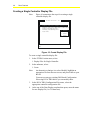
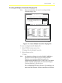
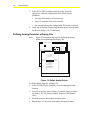
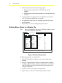
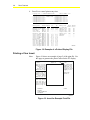
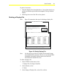
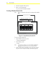
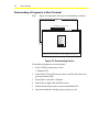
1
FANs 637.5, 1637.5 Zone Terminal Section Issue Date 0400 APPLICATION NOTE Zone Terminal Configuring the Zone Terminal............................................................3 Introduction......................................................................................................... 3 Key Concepts.....................................................................................................*5 About This Document ..................................................................................................... 5 Zone Terminal ............................................................................................................... *6 Zone Terminal Configuration ........................................................................................ 16 Procedure Overview ......................................................................................... 25 Detailed Procedures ........................................................................................*27 Starting ZT PRO .......................................................................................................... *27 Creating a Single Controller Display File....................................................................... 30 Creating a Multiple Controller Display File .................................................................... 31 Defining Analog Points for a Display File ...................................................................... 32 Renaming Analog Points for a Display File ................................................................... 33 Defining Binary Points for a Display File ....................................................................... 34 Renaming Binary Points for a Display File .................................................................... 35 Saving a Display File .................................................................................................... 36 Printing a Display File ................................................................................................... 37 Printing a Clear Insert ................................................................................................... 38 Deleting a Display File .................................................................................................. 39 Creating a Weekly Schedule File .................................................................................. 40 Saving, Printing, or Deleting a Weekly Schedule File.................................................... 41 *Indicates those sections where changes have occurred since the last printing. © 2000 Johnson Controls, Inc. Code No. LIT-6375140 www.johnsoncontrols.com 2 Zone Terminal Creating a Holiday Schedule File .................................................................................. 41 Printing or Deleting a Holiday Schedule File ................................................................. 42 Creating a Load File ..................................................................................................... 42 Selecting Display Files for the Load File ....................................................................... 43 Selecting Schedule Files for the Load File .................................................................... 44 Completing and Saving the Load File ........................................................................... 45 Printing and Deleting Load Files ................................................................................... 45 Downloading a Program to a Zone Terminal................................................................. 46 Troubleshooting ..............................................................................................*47 Examples ........................................................................................................... 52 Introduction................................................................................................................... 52 Example 1-- Setup for Typical AHU Job........................................................................ 52 Example 2-- Setup for Multiple VAV Job ....................................................................... 54 Example 3-- Setup for Multiple UNT Job ....................................................................... 56 Example 4-- Factory Supplied Universal Files............................................................... 57 *Indicates those sections where changes have occurred since the last printing. Zone Terminal 3 Configuring the Zone Terminal Introduction The Zone Terminal (ZT) is a hand-held or wall-mounted Person-Machine Interface (PMI)for the Metasys® Application Specific Controllers (ASCs). It has the versatility to connect to a controller in several ways and allows the user to monitor or adjust setpoints and time scheduling within a specific zone. This application note provides an overview of the setup, functions, and configuration of the Zone Terminal. This document describes how to: • start ZT PRO • create a single controller display file • create a multiple controller display file • define analog points for a display file • rename analog points for a display file • define binary points for a display file • rename binary points for a display file • save a display file • print a display file • print a clear insert • delete a display file • create a weekly schedule file • save, print, or delete a weekly schedule file • create a holiday schedule file • print or delete a holiday schedule file 4 Zone Terminal • create a load file • select display files for the load file • select schedule files for the load file • complete and save the load file • print and delete load files • download a program to a zone terminal Zone Terminal 5 Key Concepts About This Document This section of the HVAC PRO User’s Manual describes the setup process required for downloading the Zone Terminal. If an HVAC (Heating, Ventilating, and Air Conditioning) system includes ZTs, the installation process includes setup of the ZTs. This setup results in a customized ZT that monitors and controls a selection of points in a particular controller or group of controllers. The setup, diagrammed in Figure 1, involves both a decision process and a configuration process: • The decision process--determines the best way to customize the ZT template, time schedule, and decimal place. • The configuration process--creates files and links an application specific controller’s configuration to a specific ZT file. Configuration requires ZT PRO software, which is part of the HVAC PRO™ software package. Your Decision Process 4 TH F LO O R -Z O N E OU TD OO R TE MP Z ON E TE MP S T A T I C P RE S S P M X D A I R LO L M T NI GH T HE AT S P NI GH T Download MI XE D CO OL AI R TE MP ST AT IC P RE S O U T D O O R DA M P E R HE AT IN G CM D CO OL IN G DI SC H DI SC H Configuration Process SP SU PP LY F AN ON OF F A IRF LOW BI O C C U P I ED B I S H U T D O WN B I S P L Y F AN C M D E CON MO D E O CCU PD M OD E S HUT DW N M OD E S P L Y F AN A L M C O O L S TA G E 1 C O O L S TA G E 2 CM D C OOL S TA G E SP C OOL S TA G E H EAT S TA G E C MD SU PP LY C FM Z O N E H I GH L M T EC ON OM IZ ER S P D A M P E R M IN P O S ZT PRO Software I N S E RT 9 9 TE MP AI R AI R 3 H EAT S TA G E H EAT S TA G E H EAT S TA G E 3 4 1 2 3 4 E XHS T FA N 1 E XHS T FA N 2 Zone Terminal ZTSETUP Figure 1: ZT Setup Note: To configure (establish parameters of) a ZT, you need HVAC PRO software and either a VAV (Variable Air Volume), AHU (Air Handling Unit), UNT (Unitary), or PHX (Phoenix Fume Hood) controller configuration file. 6 Zone Terminal Zone Terminal Zone Terminal and ZT PRO Software The ZT PRO software tool is part of the HVAC PRO software package. ZT PRO sets up files, based on a previously configured controller or controllers, and then downloads the files to a Zone Terminal. The Zone Terminal is a hand-held or wall-mounted person-machine interface for the Metasys Application Specific Controllers (ASCs). It has the versatility to connect to a controller in several ways and allows the user to monitor or adjust setpoints and time scheduling within a specific zone. Application Details The Zone Terminal is used to monitor or adjust setpoints and for time scheduling of occupied, warmup/cooldown, or shutdown zone conditions. ZT PRO software establishes the ZT parameters for the controller’s analog setpoints and values. After downloading the ZT from the ZT PRO, the ZT connects to: • a VAV/UNT/PHX through a TE-6100 Zone Sensor • an AHU directly • an AHU through a Function Module Kit or a Relay Kit • an AHU or UNT through an M100C Actuator Theory of Operation The parameters established with the ZT PRO make the Zone Terminal an easy-to-use hands-on device with which you can: • quickly identify an alarm and its location • monitor and adjust up to 18 analog points • monitor 18 binary points • extend a daily time schedule using Occupied Extend • add or modify daily, holiday, and temporary time schedules 7 Zone Terminal Displays The ZT uses a Liquid Crystal Display (LCD) divided into three sections from top to bottom (Figure 2). Each display includes: • five, seven segment digits • decimal points • colon Display Item List ROOFTOP ZTU INSERT 12 2 COOL SET PT HEAT SET PT WARMCOOL ADJ ACT CLG SP ACT HTG SP 3 DISCH TEMP CLG % ON HTG % ON ECON % OPEN MIN POS % OPN Mode Selector Button ON Display Area 1 1 OUTDOOR AIR ZONE TEMP STATIC STEPT MIXED AIR LL SP NIGHT HTG STPT NIGHT CLG STPT Display Button 1 Mode Selector Panel Warning Signal Display Indicator Dot Display Area 1 2 Display Area 1 3 Operating Mode Indicator MONITOR ADJUST TIME SCHEDULE PASSWORD ENTER On/Off Status OFF FAN COOL STG #1 COOL STG #2 HEAT STG #1 HEAT STG #2 OCCUPIED A/C LIM OPN CHECK FAN CHECK CLG CHECK HTG CHECK ECON DIRTY FILTR FAN STATUS ECON ENABLE TEMP OCC WARMUP MODE CLG LOCKOUT HTG LOCKOUT ALARM Alarm Light Up/Down Arrow Keys Door MAP1RT4 Figure 2: Zone Terminal To the left of the display are 18 cursors (●) and triangles (▲), 6 per display. The cursors indicate current position in the respective display. The names or labels for each item are specified with the ZT PRO. When flashing, the triangles indicate an alarm condition in the corresponding analog points. The right side of the ZT display includes 18 pairs of binary indicators-a bar ( | ) for On, and a circle (❍) for Off. These symbols flash when the respective binary point is in alarm. Five LEDs (Light-Emitting Diodes) located in the bottom panel include four green Mode Indicators and one red Alarm Indicator. The Alarm Indicator LED flashes when any analog or binary point is in alarm. 8 Zone Terminal Keys Refer to Figure 2 to locate each of the seven ZT keys. Table 1: Keys Key Description Display Button 1, 2, 3 Moves the cursor through insert items Operating Mode Selector Moves the LED to the desired operating mode: Monitor, Adjust, Time Schedule, Password (↑ ↑) or (↓ ↓) Adjust Up or Down--changes the numbers in the displays Enter Commits adjustments Required Hardware for ZT Operation The following hardware items are required for Zone Terminal operation: • AHU, UNT, VAV, or PHX controller with power applied • AS-ZTU100 Zone Terminal comes with: - a 6-pin telephone-style coiled cord - one Time Schedule overlay (remove the paper backing) - three clear inserts with setpoint labels (remove protective plastic backing). UNT/VAV inserts match common configurations right out of the box. The ZT matches the most-used AHU configuration: Mixed Air Single Path. Optional Hardware for ZT Operation Note: For more specific information, see the Zone Terminal Technical Bulletin (LIT-6363014) in the Metasys Application Specific Controllers Technical Manual (FAN 636.3). The following hardware items are optional: • TE-6100 Zone Sensor • AS-FMK100 Function Module Kit • AS-RLY100 Relay Kit or M100C Actuator • AS-ZTUWMB Wall Mount Base • AS-ENC100 Enclosure • AS-ZTUUMB Utility Mounting Base with Screws • AS-ZTUBAG Carrying Case Zone Terminal Required for ZT Downloading The following are required for Zone Terminal downloading: • AS-CBLPRO-1 or AS-CBLPRO-2 • IBM compatible computer or laptop • WS-WINPRO HVAC PRO for AHU, UNT, VAV, or PHX configuration files • clear overhead transparency film for the customized inserts • AS-CBLCON-0 or AS-AHU101 and AS-FMK100 Note: AS-CBLPRO-1 or -2 must be used to download the ZT. AS-CBLPRO-0 is not compatible for downloading. Software ZT PRO is part of HVAC PRO software. This easy-to-use tool establishes analog setpoints and values, prepares the inserts, and downloads the ZT’s database. The program runs on an IBM PC/XT/AT, PS/2, or any 100% compatible computer. You install ZT PRO when you install HVAC PRO by selecting the ZT PRO option. For more information on installing HVAC PRO or ZT PRO, refer to Configuration Tools Software Installation Instructions (LIT-6375025). Figure 3 is an overview of the ZT configuration and downloading process. More specific information comes later in this section. 9 10 Zone Terminal Start ZT PRO (from icon or DOS prompt) ● ● ● ● ● ● ● ● ● Select Configure ZT Files Define display files for single or multiple controllers. Define Weekly Schedules. Define Holiday Schedules. Define ZT Configuration Load File Press F2 and select up to three display files. Press F2 and select Weekly and Holiday Schedules, which must be executed from ZT. Press F2 and select display file that corresponds to appropriate controller. Select hardware parameters. Specify Password access numbers. Print the Insert and photocopy onto an overhead transparency. Exit ZT PRO Start ZT PRO (from icon or DOS prompt) ● ● ● ● ● ● Select Download ZT Attach cable to ZT AS-CBLCON-0 and AS-CBLPRO-1 or AS-CBLPRO-2 connection. Set switch at AS-CBLCON-0 to download. Select the desired load file to download. Select the communication port. When Download Complete message displays on the screen, press any key to return to Main ZT PRO Menu. (PC [Personal Computer] displays at ZT during download; resets when download is complete.) Unplug cable from ZT AS-CBLCON-0. Reset switch to normal. Exit HVAC PRO DWNLDZT Figure 3: Overview--Configuring and Downloading the ZT Zone Terminal 11 Design Considerations The decision process requires that you consider the characteristics of a particular HVAC (Heating, Ventilating and Air Conditioning) system, the objectives of the system users, and the responsibilities of the system maintenance personnel (the ZT users). With these considerations in mind, you must decide: • Which controllers require a dedicated ZT for maintenance personnel access? • Which controllers can be grouped for access through a common ZT? • How are controller points and operations organized for viewing convenience? • What names and adjustment capabilities are appropriate through the ZT display access? • Does control access through each ZT require security, and should such security be divided into two levels? Notes: These decisions are interactive. Before making any of these decisions, review all of the considerations involved with each decision. If practical, also discuss the implications of these decisions with the ZT users. Each time a controller configuration is altered, the ZT must be redownloaded. Therefore, program the ZT after all controller configurations are complete and stable. The ZT presents false or misleading information if changes are made to the controller configuration after the ZT is downloaded. Single Controller vs. Multiple Controller Display Decide on the number of ZTs required for the HVAC system, and decide which controllers will be accessed by each ZT display. Considerations are: • The control requirements of the user--most users prefer simple controls that allow them to easily solve ordinary problems. A full range of control capabilities may not be helpful or useful. Provide just enough control to solve ordinary problems. Note that the definition of ordinary is site dependent. • ZT capabilities--refer to Table 2 for the number of displays and the range of controllers and the points accessible through each display. Determine the minimum number of ZTs required to meet the control requirements. 12 Zone Terminal • Convenience--a dedicated ZT mounted right on a critical AHU in a large installation provides quick access and eliminates the need to find and bring the correct ZT to do a task. • Cost--provide good value. Reconsider the convenience and control requirements against the total number of ZTs required. You can configure each ZT with up to three different controller applications. For each application, you can: • Select the specific controller points available for display and control. • Access points in only one type of controller: AHU, VAV, UNT, or PHX. • Configure for access to controllers that have: - a single, specific configuration by using the single controller display - up to 12 different configurations by using the multiple controller display Single Controller Display Use the single controller display for complete access to a controller. With the single controller display, you can: • Select any points in the controller, although the number of points available through each display is limited. • Schedule the controller. Multiple Controller Display Use the multiple controller display for limited access to several similar controllers. With the multiple controller display, you can: • Select up to 12 controller configurations. • Select only points common to the specified controllers. Zone Terminal 13 Display Type Summary Table 2 summarizes the capabilities of the ZT display types. Table 2: Display Types Consideration Controller Characteristic Display Single or Multiple Controllers Each ZT can be configured for up to three applications. These can be a mix of single controller or multiple controller. Controller Access Single Controller Each single controller application is automatically encoded so that it can access only one controller configuration. Controllers with identical configurations can be accessed using a single controller display. Multiple Controller Each multiple controller display can access up to 12 controller configurations. All controllers accessed by a multiple controller display must be of the same type AHU, VAV, UNT, or PHX controller. Scheduling Single Controller Each ZT can schedule just one controller. Networked ASCs cannot be scheduled using the ZT. Standalone ASCs require a ZT for scheduling. Points Single Controller Any points in one controller configuration can be accessed. Multiple Controller Only points common to all the selected controller configurations can be accessed. The only exception occurs when all selected controller configurations are Single Duct. In this instance, all points are accessible. Occupied Extend Occupied Extend is a special feature that lets you temporarily extend the occupied mode of operation without going into the Time Schedule mode. If the system uses the Occupied Extend feature, it must be listed as one item on the template (insert). No matter what Begin/End time is scheduled for the current day, the user decides how long the system should remain on. For example: it is currently 3:30 p.m. and the user wants the building to stay on until 11 p.m. This is an extension of 7 hours and 30 minutes, which is entered on the ZT. Any amount of time from 00:00 to 23:59 can be entered in Occupied Extend. 14 Zone Terminal Enable Occupied Extend You can enable occupied extend control of a controller from the ZT if: • The controller is accessed through a single controller display. • Time Schedule files are defined for the controller. • The controller connected to the ZT is not part of N2 Network. To enable this function, select the Occ Extend point from the list of analog setpoints when defining the Single Controller Display. Organizing Points Arrange binary points using the following considerations: • Group logically by function. • Organize consistently relative to other facility ZTs. • Organize consistently relative to analog point organization. Arrange analog points using the following considerations: • Locate related points in separate display groups so that these points can display at the same time. • Organize consistently relative to other facility ZTs. Organize points in the AHU ZTs so that related points can be viewed simultaneously. For example: • outdoor air • discharge air • zone temperature Also locate setpoint values and actual measured values in separate display groups. This setup makes a display, such as Figure 4, possible during troubleshooting. Zone Terminal Building 3 Floor 4 AHU12 OUTDOOR TEMP ZONE TEMP STATIC PRES SP MXD AIR LO LMT NIGHT HEAT SP NIGHT COOL SP INSERT 12 ON MIXED AIR TEMP STATIC PRES OUTDOOR DAMPER HEATING CMD COOLING CMD DISCH AIR SP 15 OFF AIRFLOW BI OCCUPIED BI SHUTDOWN BI SPLY FAN CMD ECON MODE OCCUPD MODE SHUTDWN MODE SPLY FAN ALM DISCH AIR TEMP DISCH LOW LMT ZONE HIGH LMT DAMPER MIN POS ZTTBL Figure 4: Troubleshooting Display In this case, various commands can be checked, such as the cooling command, to determine why the discharge temperature is higher than the setpoint. Since the binary point values are always displayed, group them by functions, such as the modes of operation--OCCUPIED, SHUTDOWN, and WARMUP. Renaming Points For the ZT user, you can: • Change the point names displayed at the ZT. • Define the significant decimal characters for each analog value. • Enable adjustment of an analog point value. • Limit the range of adjustment available on an analog point. • Enable alarm on a binary point state. 16 Zone Terminal Security Levels Evaluate security requirements of the facility to determine if a password is appropriate. Use both password levels if ZT users have distinctly different responsibilities or capabilities. The ZT can be configured to limit user access to the setpoint adjust and the time schedule modes based on a 3-digit password. Two passwords are possible per ZT: • The first provides full access to all modes. • The second password locks out access to the Time Schedule mode and allows setpoint adjustment. • The user can also select no password, which allows access to all levels. Note: The factory default password is 246. Zone Terminal Configuration ZT PRO Files This section provides background information on ZT PRO files and describes the ZT configuration process. Figure 5 diagrams the interaction between the various files involved in a ZT configuration. Table 3 provides additional details on each of these files. Directory Clear Insert Number Generator Controller Configuration Files AHU "NAME".CFG 1 No./Display File 1 File/Display File Single Controller Display Files AHU "NAME".AHS UNT VAV "NAME".UNS "NAME".VAS UNT "NAME".CFG PHX AHU "NAME".PHS "NAME".AHM Schedule Files 2 to 12 Files/Display File UNT "NAME".UNM "NAME".WKS "NAME".HDS 1 Each/ Load File VAV PHX "NAME".PHM "NAME".VAM 3 Display Files/ Load File Load Files Holiday PHX "NAME".CFG Multiple Controller Display Files 3 Display Files/ Load File Weekly VAV "NAME".CFG "NAME".ZTO Download ZT Print Files "NAME".ZPW "NAME".ZPH "NAME".ZPD "NAME".ZPL ZTCONF Figure 5: ZT Configuration Files Zone Terminal 17 Table 3: File Descriptions File Extension Contents Origin Controller Configuration .CFG for AHU .CFG for VAV .CFG for UNT .CFG for PHX Definition of points and how they interact in controller. HVAC PRO controller configuration step Single Controller ZT Display .AHS for AHU .VAS for VAV .UNS for UNT .PHS for PHX Controller points selected for ZT display. Points are from a single controller configuration file. Point selections include configuration of ZT display and of user interface. ZT PRO Action menu Item 1/Create Multiple Controller ZT Display .AHM for AHU .VAM for VAV .UNM for UNT .PHM for PHX Controller points selected for ZT display. Points are from set of points common to multiple controller configuration files. Point selections include configuration of ZT display and of user interface. ZT PRO Action menu Item 2/Create ZT Display Print .ZPD Listing of configured points: includes names, positions in ZT display, and display parameters. ZT PRO Action menu Items 1, 2/Print ZT Weekly Scheduling .WKS Daily start and stop times for the occupied, warmup, and shutdown periods assigned to a controller. ZT PRO Action menu Item 3/ Create ZT Weekly Scheduling Print .ZPW Listing of daily start and stop times for the occupied, warmup, and shutdown periods assigned to a controller. ZT PRO Action menu Item 3/Print ZT Holiday Scheduling .HDS Holiday dates with start and stop times for the occupied, warmup, and shutdown periods assigned to a controller. ZT PRO Action menu Item 4/Create ZT Holiday Scheduling Print .ZPH Listing of holiday dates with start and stop times for the occupied, warmup, and shutdown periods assigned to a controller. ZT PRO Action menu Item 4/Print ZT Load .ZTO Typically includes: ZT PRO Action menu Item 5/Create • three display files • access password • hardware parameters • weekly schedule file • holiday schedule file ZT Load Print .ZPL Listing typically includes: • display files ZT PRO Action menu Item 5/Print • access password • hardware parameters • weekly schedule file • holiday schedule file Clear Insert Number Generator .NBR Numbers the clear inserts for display files within directory: • uses lowest available number • numbers from 1 to 96 • reserves 97 to 99 for factory configurations • rolls over to 1 if all numbers used Automatic in ZT PRO 18 Zone Terminal Single Controller Display You can configure a ZT display for control of a particular controller. The process starts with the controller’s configuration file. From this file, define a single controller display file. Later, when defining the ZT load file, include this display file. Note: ZT PRO does not read Configuration files that have been created by the DOS version of HVAC PRO. You must recreate pre-existing DOS based Configuration files using HVAC PRO. Multiple Controller Display You can configure a ZT display for control of up to 12 controller configurations of a given type. The process starts with selection of the configuration files for the controllers. The ZT PRO assembles a temporary file containing points common to all controller configurations. From this file, you define a multiple controller display file. Later, when defining the ZT load file, you include this display file. Load File Once you have created the display and schedule files for a ZT, build the load file. You must define the display files used (up to three), the weekly and holiday schedule files used (one each, if any), some hardware data, and the access passwords. Load File Download Once you have created the load file for a ZT, download the file to a ZT. The process requires physical connection of the ZT and HVAC PRO PC (Personal Computer), selection of the load file, and the download command. When downloading the ZT without a controller, 24 VAC power must be accessed from a transformer. Where power is accessed through an XFR100 transformer, splice the wire coming from the transformer according to Figure 6. This is only required when you do not have an AHU, VAV, UNT, or PHX controller available. Refer to Zone Terminal Technical Bulletin (LIT-6363014) in the Metasys Application Specific Controllers Technical Manual (FAN 636.3) for other hardware connections for downloading. Figure 6 summarizes the physical connection of the ZT to your PC. 19 Zone Terminal Transformer Green Orange Brown Splice Here Splice Here AS-CBLCON-0 24 VAC Reset Button HVAC PRO AS-CBLPRO-2 Molex Connector Pin 3 = COM Pin 2 = 24 VAC 6-pin RJ12 Phone Plug Zone Terminal Switch must be in Download position. XFRZT Figure 6: Physical Connection Analog Points Only points selected as adjustable in the ZT PRO can be adjusted with the ZT. Points are adjustable within the limits defined by ZT PRO. If an analog point has a setpoint that is outside of the ZT PRO defined adjustable limits, when the user tries to adjust the value, the ZT, upon the first adjust key press, goes to the value corresponding to the limit. The user cannot make adjustments outside of those limits. If a point is selected in the ZT PRO as being adjustable, but does not flash when selected on the ZT, an N2 or Zone Bus laptop is overriding the point. The ZT displays analog values based on the following priority: Table 4: Analog Values Priorities Priority Value Priority 1 Override from N2 Priority 2 Command from N2 Priority 3 Override from Zone Bus laptop--race condition with N2 Priority 4 Controller value 20 Zone Terminal If an N2 overrides a point while the user is adjusting it, the N2 overrides the point. The user is allowed to finish the adjustment, or save or discard the adjustment. The point is not adjustable until the override is released. The ZT displays the overridden value. Only AIs report alarms. Alarm limits are determined by HVAC PRO not ZT PRO. How the point was defined with HVAC PRO is how the alarm triangle works on the ZT. Controller points which are displayed on the ZT show an alarm if the point is unreliable. This occurs only if the user enables the alarm reporting for the AI (Analog Input) with HVAC PRO. ADFs cannot report alarms. AOs cannot report alarms. If an AI is overridden by N2 or a Zone Bus laptop beyond the alarm limits or the unreliable limits (sensor limits), the triangle for this AI flashes on the ZT. Point adjustments in ALL cases are made to the controller’s E2 PROM and are permanent. Binary Points Binary points can be BIs, BOs, or BDs. Binaries can never be adjusted or commanded. They are read only. Display rules and priorities are the same for binaries as for analogs. See priorities as listed in the Analog Points topic in this section. Alarms for binaries are different than for analogs. • BOs do not report alarms. • BIs report alarms, and the conditions for alarm reporting are set by HVAC PRO. • BDs also report alarms at the ZT, and the conditions are set by the ZT PRO. • The user defines whether a binary is to have alarm reporting enabled. The normal (non-alarm) state is also defined by the user. • When an alarm-enabled binary point in the ZT is not in its normal state, the binary will flash on the ZT. When the binary returns to its normal state, the binary will stop flashing on the ZT. • If a binary is commanded or overridden by N2 or a Zone Bus laptop to a non-normal state, the binary flashes if the point is alarm-enabled. Zone Terminal 21 Passwords The ZT PRO allows the user to enter none, one, or two passwords. If the user does not enter a password, access is given to all the ZT modes of operation. Note, however, that if the ZT is not configured for time scheduling, the user is denied access to time scheduling. One password is for adjust privileges only. The other password is for adjust and time scheduling privileges. A user can enter the same password for both levels and be allowed access to both adjust and time scheduling. A feature of the ZT called Idle Key Timeout is set at the ZT PRO, which tells the ZT to return to Monitor mode and cancel the user’s access (forcing re-entry of the password) after the keyboard remains idle for the specified period of time. Time Scheduling You can configure a ZT for weekly and holiday schedule control of one controller configuration. Schedules require a single configuration display on the ZT. The following rules apply to time scheduling: • The Zone Terminal reads and compares only one Begin and one End time for the current day. • Once Midnight is reached, the next day’s schedule takes over. • One Begin and One End time for each day must be scheduled for Occupied, Warmup, and Shutdown. • If no transition is desired for one entire day, enter 00:00 Begin and 24:00 End to keep the controller On (Occupied) for that day. If you want the controller Off (Unoccupied) for the day, enter 24:00 Begin and 00:00 End. This procedure applies to Occupied, Warmup, and Shutdown. • When the Begin and End times are equal or entered as 24:00 or 0:00, that mode will not execute. Time Scheduling can only be used on a single controller configuration. That is, the ZT is expected to be dedicated to the controller, which is in need of time scheduling. Time scheduling commands are written to the E2PROM locations of Occupied, Warmup, and Shutdown, and are permanent. Therefore, do not remove the ZT from the associated controller when time scheduling is in use. The user can schedule any combination of Occupied, Warmup, and Shutdown based on availability in the controller configuration. 22 Zone Terminal Availability in the controller configuration is defined as having the desired point (Occupied, Warmup, Shutdown) as a writable BD (Binary Data) point in the configuration. Hardware BI (Binary Input) points are not schedulable. If a user is scheduling a controller via external hardware clock to the controller’s hardware BI, the user must reconfigure the controller’s download to make the schedulable hardware BI a BD point. The initial schedule for the associated controller can be originally specified at the ZT PRO and modified at the ZT. Since the precision of schedules is specified in Hours and Minutes, the schedule activation is +/- one minute. This means that if a user is watching the ZT clock, and sees the time roll over to the start of a scheduled event, it may be up to one minute before the user sees the system switch states. Table 5: ZT Time Schedule Priorities Priority Value Priority 1 N2 override/command schedule Priority 2 ZT occupied extend Priority 3 Temporary schedule Priority 4 Holiday schedule Priority 5 Day of the week schedule Time Scheduling works in one of two modes: Local and Network. Local The ZT is standalone with a single controller. The schedule for running the controller is in the ZT. ! CAUTION: Do not disconnect the ZT from the controller during time scheduling. The last state in the controller is retained forever. Network In Network scheduling mode, the ZT assumes that the scheduling commands are coming from the N2 Network headend. When configured with this option at the ZT PRO, the ZT never allows access to the Time Scheduling mode. Disconnecting the ZT in this mode has no affect on the controller’s operation. Zone Terminal 23 Occupied Extend Occupied Extend is an extension of time scheduling. Occupied Extend is only available to standalone configurations with Occupied as a BD. Occupied Extend is only operable when time scheduling is operable. That is, if the user picks Occupied Extend as one of the analog points, and the controller that the ZT is plugged into is not the one designated as the time scheduled controller, the ZT does not allow the user to set an Occupied Extend time. The user sets an Occupied Extend duration. This duration is measured in hours, minutes, or both. The duration is measured from the time it is entered by the user. For example, assume it is 3:00 p.m. (15:00) and the occupied schedule is Occupied until 6:00 p.m. (18:00). If the user wants the building to stay occupied until 9:00 p.m. (21:00), the user would set Occupied Extend up for 6:00 (6 hours, and 00 minutes). The ZT can be downloaded with three configurations in one download. Theoretically, the user could select (via the ZT PRO) three configurations so that each has Occupied Extend. Since only one of the three configurations can be linked with the time scheduling when plugged into the other two controllers, Occupied Extend is therefore not adjustable. Timekeeping Timekeeping works with or without an N2 Bus present and needs no user intervention except to set the time and date on the ZT. The time in the controller is updated by either the N2 or the ZT. The N2 has the highest priority. There are three clocks to be synchronized in the system: • controller clock • ZT clock • N2 clock If there is an N2 online, it updates the clock in the controller. The ZT synchronizes its clock to the controller time so that all are the same. If there is no N2 online, the ZT sends its time to the controller to keep it synchronized with the ZT. Anytime the ZT is powered up, it waits five minutes before setting or synchronizing the clock in the controller. However, time scheduling updates continue uninterrupted. Anytime the ZT senses the N2 going from Offline to Online, the ZT waits five minutes before synchronizing its clock so the N2 has time to update the time in the controller. 24 Zone Terminal When N2 is online, it controls the time and, therefore, the ZT does not allow adjustments to time or date. These items become read only. Since the controller holds the N2 Comm status for ten minutes after N2 really is no longer present, the time and date in the ZT cannot be modified during this ten minute duration. After the time expires, the time and date can again be modified. If the N2 comes online while the user is adjusting time or date, the ZT allows the user to complete or discard their adjustment. The N2 takes over and prevents further adjustments to time and date. Zone Terminal 25 Procedure Overview Table 6: Configuring the Zone Terminal To Do This Follow These Steps: Start ZT PRO From Windows, double-click on the ZT PRO icon in the HVAC PRO program group. To start ZT PRO from DOS, change to the directory where ZT PRO is stored and type ZTSHELL. Strike any key to move past the copyright display. Verify the file storage path and press Enter. Refer to the instructions at the bottom of the screens for options. Create a Single Controller Display File In the ZT PRO Action menu, select 1. Display Files for Single Controller. In the submenu, select Create. Select the appropriate controller configuration file. Enter the name for new display file. Create a Multiple Controller Display File In the ZT PRO Action menu, select 2. Display Files for Multiple Controller. In the submenu, select Create. Select the appropriate controller configuration file. At the top of the Data Display template that opens, enter the name for the new display. Define Analog Points for a Display File In the ZT Data Display Template, select an analog data point location. Press F2. Position cursor on desired point and press Enter. Repeat steps for each analog data point location. If necessary, press F3 to reorder points. To reorder points, select the source location, press F3, and move the cursor to the destination location. Press Enter to move the point from the source location to the destination location. If necessary, press F4 to delete the point in selected analog point location. Rename Analog Points for a Display File Select an analog point in the ZT Data Display Template. Press F5. Enter a point name. Define the decimal format for the display digits. Use the spacebar to toggle the point to adjustable (Y) or back to (N). For adjustable points, enter the operating range limits placed on the ZT operator. Repeat steps for each analog data point location. Define Binary Points for a Display File In the ZT Data Display Template, select a binary data point location. Press F2. Position cursor on desired point and press Enter. Repeat steps for each binary data point location. If necessary, press F3 to reorder points. To reorder points, select the source location, press F3, move the cursor to destination location, and press Enter. If necessary, press F4 to delete the point in a selected binary point location. Rename Binary Points for a Display File Select a binary point in the ZT Data Display Template. Press F5. Enter a point name. Use the spacebar to toggle the point to alarm enabled (Y) or back to (N). For alarm enabled points, enter the normal state. Repeat steps for each binary data point location. Save a Display File In the ZT Data Display template, press Esc. Type in a name for the ZT display file. Press Enter. Print a Display File In the ZT PRO Action menu, select 1. Display Files for Single Controller. In the submenu, select Print. In the listings of Display files, select files to be printed. Press F6. Enter Y in answer to question Send output to a printer? Press Esc to cancel print at any time. Print a Clear Insert Print the Display file as described above. Photocopy sheet 2 of the file on clear plastic. Delete a Display File In the ZT PRO Action menu, select 1. Display Files for Single Controller. In the submenu, select Delete. In the listings of Display files, select files to delete. Press F6. Enter Y in answer to the question Are you sure this file should be deleted? Continued on next page . . . 26 Zone Terminal To Do This (Cont.) Follow These Steps: Create a Weekly Schedule File In the ZT PRO Action menu, select 3. Weekly Scheduling File. In the submenu, select Create. In the ZT PRO Weekly Scheduling screen, enter daily start and stop times for the Occupied, Warmup, and Shutdown periods. Save, Print, or Delete a Weekly Schedule File Refer to the procedures for display files. Create a Holiday Schedule File In the ZT PRO Action menu, select 4. Holiday Scheduling File. In the submenu, select Create. In the ZT PRO Holiday Scheduling screen, enter the holiday dates and start and stop times for the Occupied, Warmup, and Shutdown periods. When your holiday schedule is complete, press Esc. Type in a name for the schedule file. Press Enter. Print or Delete a Holiday Schedule File Refer to the procedures for display files. Create a Load File In the ZT PRO Action menu, select 5. Load File. In the submenu, select Create. Select Display Files for the Load File In the Load File Data screen, position the cursor at FILE NAME#1 and press F2. Highlight an appropriate file. Press Enter to select a highlighted file. Press F6. Press Esc to cancel all selects if desired. Select Schedule Files for the Load File In the Load File Data screen, position the cursor at Weekly Schedule and press F2. In the submenu, select a weekly schedule file from the list of previously defined schedule files. In the Load File Data screen, advance the cursor to Holiday Schedule and press F2. In the submenu, select a holiday schedule file from the list of previously defined schedule files. In the Load File Data screen, advance the cursor to Display File and press F2.In the submenu, select a display file from the list of Single Controller Display files currently loaded. Complete and Save the Load File In the Load File Data screen, position the cursor at a hardware value and edit values as indicated in Table 9. In the Load File Data screen, position the cursor at the password and edit value. In the Load File Data screen, press Esc. Type in a name for the load file. Print and Delete Load Files Refer to the procedures for display files. Download a Program to a Zone Terminal In the ZT PRO Action menu, select 2. Download ZT. In the Select ZT Load File menu, select a load file from the list of previously defined files. Press Enter to select the COM port. Press Enter to display the download screen. Follow the directions on the screen to download the ZT. Once the download is complete, press any key to exit. Zone Terminal 27 Detailed Procedures Starting ZT PRO To start ZT PRO: 1. From Windows, click on the Start button and select Programs > Configuration Tools > ZT PRO. To start ZT PRO from DOS, change to the directory where ZT PRO is stored and type: ZTSHELL The ZT PRO Copyright screen displays (Figure 7). ZT PRO CONFIGURATION, AND DOWNLOAD UTILITY Release 7.00 Download Controller (c) Copyright, Johnson Controls Inc., 1998 All rights reserved. The following program is the exclusive property of Johnson Controls, Inc. and its use is restricted by license agreement to the system with which it was furnished. The program contents are confidential and may not be disclosed or used outside the system without the express written consent of JOHNSON CONTROLS. This program is further protected by federal copyright law as an unpublished work and any unauthorized reproduction is prohibited. Press any key to continue... CPYRITE2 Figure 7: Copyright Display 28 Zone Terminal 2. Strike any key to move past the copyright display. ZT PRO displays a prompt requesting the storage path for ZT PRO files (Figure 8). HVAC PRO Path used for all files accessed by this utility will be [ C:\WINPRO\FILES ] <ESC>Exit Enter desired changes, Press <ENTER> to continue FILEPATH Figure 8: File Path Verification Prompt 3. Verify the file storage path and press Enter to move into ZT PRO. Figure 9 summarizes the access steps. ZT PRO CONFIGURATION, AND DOWNLOAD UTILITY RELEASE 7.00 HVAC PRO Path used for all files accessed by this utility will be: [C:\WINPRO\FILES ] HVAC PRO 1. Configure ZT files 2. Download ZT ZT PRO - Version 7.00 1. Display Files for Single Controller <ESC> Action Menu 2. Display Files for Multiple Controller 3. Weekly Scheduling File 4. Holiday Scheduling File 5. Load File <ESC> Action Menu Press <ENTER> to continue <ESC> Exit Press <ENTER> to select ZTPROACC Figure 9: ZT PRO Access Zone Terminal Refer to the instructions at the bottom of the screens for options. In these instructions, key combinations are separated by a slash “/.” Common commands are listed in Table 7. Table 7: Common Screen Commands Key Function Esc Exit and return to next highest menu. Arrow Move cursor through menu. Tab and Shift/Tab Move cursor between lists. Enter Select item from current cursor position. F7 View a highlighted file. 29 30 Zone Terminal Creating a Single Controller Display File Note: Figure 10 summarizes the steps for creating a single controller display file. ZT PRO-Version 7.00 ZT PRO ACTION MENU 1. 2. 3. 4. 5. Display Files for Single Controller Display Files for Multiple Controller Weekly Scheduling File Holiday Scheduling File 1. Create Load File 2. Modify 3. Print 4. Delete <ESC> Use ZTPFIG7 Figure 10: Create Display File To create a single controller display file: 1. In the ZT PRO Action menu, select: 1. Display Files for Single Controller 2. In the submenu, select: 1. Create Note: An alternative technique is to select Modify, highlight an appropriate file from the next screen, and press Enter to open the file. You must recreate pre-existing DOS based Configuration files using HVAC PRO before you can modify them. 3. In the HVAC PRO Configuration Files menu, select the appropriate controller configuration file. 4. At the top of the Data Display template that opens, enter the name for new display file (1 to 32 characters). Zone Terminal 31 Creating a Multiple Controller Display File Note: Figure 11 summarizes the steps for creating multiple controller display files. ZT PRO-Version 7.00 1. 2. 3. 4. 5. Display Files for Single Controller Display Files for Multiple Controller Weekly Scheduling File 1. Create Holiday Scheduling File 2. Modify Load File 3. Print 4. Delete HVAC PRO CONFIGURATION FILES <E Pr AHU AHU1 AHU2 AHU3 AHU4 AHU5 AHU6 AHU7 AHU8 UNT UNT1 UNT2 UNT3 UNT4 UNT5 UNT6 UNT7 UNT8 VAV * * * VAV1 VAV2 VAV3 VAV4 VAV5 VAV6 VAV7 VAV8 PHX PHX1 PHX2 PHX3 PHX4 PHX5 PHX6 PHX7 PHX8 <ESC> Action Menu <F6>Continue Vertical arrow keys scroll, Press <ENTER> to select (*)/deselect FIG17 Figure 11: Create Multiple Controller Display File To create a multiple controller display file: 1. In the ZT PRO Action menu, select: 2. Display Files for Multiple Controller 2. In the submenu, select: 1. Create Note: An alternative technique is to select Modify, highlight an appropriate file from the next screen, and press Enter. However, you can only modify files created with configurations generated by HVAC PRO. Also, you cannot modify controller configuration selections for the display. You must skip Step 3 described next. Since configuration files have the same .cfg extensions, you must ensure the filenames for these controllers are different. 32 Zone Terminal 3. 4. In the HVAC PRO Configuration Files menu, select the appropriate controller configuration files. Observe these guidelines: • All controllers must be of the same type. • Up to 12 controller files can be selected. • An asterisk indicates the configuration file has been selected. At the top of the Data Display template that opens, enter the name for the new display (1 to 32 characters). Defining Analog Points for a Display File Note: Figure 12 summarizes the steps for defining the analog points accessed through this display file. INSERT TITLE: 1. 2. 3. 4. 5. Analog 6. data: INSERT 12 1. A1 Setpoints Name 1 Name 2 Name 3 Name 1 Name 2 Name 3 1. INSERT TITLE: Name 4 Name 4 2. Name INSERT 5 Name 5 12 3. 4. 1. Dataname1 1. 5. 2. Dataname2 2. 6. 3. Dataname3 3. 4. 4. 1. Dataname9 5. 5. 2. Dataname10 Analog Binary 6. 3. 6. data: data: 7. 4. 1. Dataname4 8. 5. 2. Dataname5 9. 6. 3. Dataname6 10. 4. Dataname7 11. 5. Dataname8 <ESC> Action Menu <F2> Add/Insert <F3> Reorder <F4> 12. Delete <F5> Rename 6. Use Arrow Keys to move between fields <F8> Edit Insert 13. Table 1. Dataname9 14. 2. Dataname10 15. 3. 16. 4. 17. 5. 18. 6. <ESC> Action Menu/Done <F3> Reorder <F4> Delete <F5> Rename/Adj Use arrow keys to move between fields <F8> Edit Insert Title ZTDAP..... Figure 12: Define Analog Points To define analog points for a display file: 1. In the ZT Data Display Template, select an analog data point location. 2. Press F2 to open the matrix listing of controller points available for display: AI, AO (Analog Output), Setpoints, and Monitor Only. 3. Position cursor on desired point and press Enter. 4. Repeat Steps 1-3 above for each analog data point location. Zone Terminal 33 5. If necessary, press F3 to reorder points. Reorder points moves a point from a source location to a destination location. To reorder points, select the source location, press F3, and move the cursor to the destination location. Press Enter to move the point from the source location to the destination location. 6. If necessary, press F4 to delete the point in selected analog point location. Renaming Analog Points for a Display File Note: Figure 13 summarizes the steps for defining adjustment limits and names for the analog points. INSERT TITLE: INSERT 12 1. Name3 1. 2. 2. 3. 3. 4. 4. Analog 5. Binary 5. data: 6. data: 6. 1. Orig Config Name 7. :Name3 2. 8. 3. ZT Display Name : 9. t 4. Format : XXXX.X 5. 11. INSERT TITLE: 6. imit INSERT : 13. 00.00012 1. Dataname9 imi 1. Name3 2. 1. Dataname10 15.2. 3. 2. 16.3. 4. 3. 17.4. 5. 4. 18.5. 6. 5. 6. Analog Binary 6. 7. <ESC> Done <Shift/Tab> Prev Field data: <Tab> data: 1. Next Field Enter desired value <F8> Edit Insert Table Orig Config Name :Name3 2. 3. 8. ZT Display Name : Cooling Setpoint 4. Format : Cooling 5. 10. <ESC> Enter INSERT TITLE: Adjustable : Y 12. Low Adjust Limit : 00.000 13. 12 1. Dataname9 High Adjust Limit :INSERT 0.000 14. 2. Dataname10 1. Name3 15. 1. 2. 16. 2. 4. 3. 17. 3. 5. 4. 18. 4. 6. 5. 5. Analog 6. Binary 6. data: <Tab> data: Done <Shift/Tab> Prev Field 1.Next Field 7. Name :Name3 desired value 2. <F8> Edit Orig Insert Config Table 3. 8. 4. 9. ZT Display Name : 10. Cooling Setpoint 5. Format : 11. XXXX.X 6. Adjustable ? Y 12. 1. Dataname9 Low Adjust Limit : 0000.0 13. 2. Dataname10 High Adjust Limit : 0000.0 14. 3. 16. 4. 17. 5. 18. 6. <ESC> Done Use arrow keys to move between fields Enter desired value (-9999 to 99999) ZTDALN..... Figure 13: Define Analog Limits and Names To rename analog points for a display file: 1. Select an analog point in the ZT Data Display Template. 2. Press F5 for the Rename window. 3. Enter a point name (up to 14 characters) that the ZT operator can easily recognize. 34 Zone Terminal 4. Define the decimal format for the display digits: • Integer points are predefined as XXXXX and can’t be changed. • Floating point values display alternatives for the decimal point location. 5. Use the spacebar to toggle the point to adjustable (Y) or back to (N). This selection applies only to setpoints. 6. For adjustable points, enter the operating range limits placed on the ZT operator. 7. Repeat Steps 1-6 for each analog data point location. Defining Binary Points for a Display File Note: Figure 14 summarizes the steps for defining the binary points accessed through this display file. INSERT TITLE: 1. Cooling Setpnt Name 1 Name Name Name Name INSERT #01 Output Params BI 2 3 4 5 1 2 3 4 5 Binary data: Monitor Only BO Name Name Name Name Name Name Name Name Name Name 1 2 3 4 5 Name Name Name Name Name 1 2 3 4 5 6. 2. 3. 4. 5. 6. 7. 8. 9. 10. 11. 12. 13. 14. 15. 16. 17. 18. <ESC> Cancel <TAB> Next List <Shft/Tab> Prev List Vertical arrow keys scroll, Press <ENTER> to select. ZTFIG10 Figure 14: Define Binary Points To define binary points for a display file: 1. In the ZT Data Display Template, select a binary data point location. 2. Press F2 to open the matrix listing of controller points available for display: BI, BO (Binary Output), Output Params, and Monitor Only. Scroll bars provide access to points in lists too long to be completely displayed. 3. Position cursor on desired point and press Enter. 4. Repeat Steps 1-3 above for each binary data point location. Zone Terminal 35 5. If necessary, press F3 to reorder points. Reorder points moves a point from a source location to a destination location. To reorder points, select the source location, press F3, move the cursor to destination location, and press Enter. 6. If necessary, press F4 to delete the point in a selected binary point location. Renaming Binary Points for a Display File Note: Figure 15 summarizes the steps for defining alarm monitor states and names for the binary points. INSERT TITLE: 1. Cooling Setpnt 2. Discharge Air 3. 4. og : An da 6. 1. 2. 3. Analog 4. data: INSERT #1 INSERT TITLE: 1. Fan Status 2. Damper-Close Restart Status 3. Restart Status B inar y INSERT #1 1. Cooling Setpnt 2. Discharge Air 3. 4. 5. 6. 1. 1. Fan Status 2. Damper-Close Binary 3. 3. Restart Status data: 4. 5. 6. 6. 7. 1. 8. 2. Orig Config Name: Restart Status 9. 10. ZT Display Name: Restart Status 11. 12. Alarm Enabled:"N" or "Y" 13. Normal State: ON 14. <ES >A n 15. 2. M <F 2>Add/Ins ert <F 3>R eorder > U se rro e 3. etween fields <F 8>E 16. n ys 17. 4. 18. 5. 6. <ESC> Done Use arrow keys to move between fields Use space bar to toggle between "Yes" and "No" BIDEF Figure 15: Define Binary Alarms and Names To rename binary points for a display file: 1. Select a binary point in the ZT Data Display Template. 2. Press F5 for the Rename window. 3. Enter a point name (up to 12 characters) that the ZT operator can easily recognize. 4. Use the spacebar to toggle the point to alarm enabled (Y) or back to (N). 5. For alarm enabled points, enter the normal state. 6. Repeat Steps 1-5 for each binary data point location. 36 Zone Terminal Saving a Display File Note: Figure 16 summarizes the steps for saving display files. ZT PRO-Version 7.00 FILE SAVE Filename : DISPNAM1 <ESC> Cancel Edit Filename, Press <ENTER> to continue SAVE Figure 16: Save Screen To save a display file: 1. In the ZT Data Display template, press Esc. 2. Type in a name for the ZT display file. The name: 3. • must be 1 to 8 characters • can be the same name as the controller configuration file Press Enter. Note: Creating and saving new display files automatically increments the insert number. Modifying an existing display file and saving it to the same filename retains the existing insert number. Zone Terminal 37 Printing a Display File Note: Figure 17 summarizes the steps for printing the display file. ZT PRO-Version 7.00 1. Display Files for Single Controller 2. 3. 4. 5. Display Files for Multiple Controllers Weekly Scheduling File Holiday Scheduling File 1. Create 2. Modify Load File 3. 3. Print Print SELECT SINGLE ZT PRO DISPLAY FILE TO PRINT 4. Delete AHU UNT VAV PHX <ESC> Cancel Press<* AHUTPO1 ENTER> toselect SELECT SINGLE ZT PRO DISPLAY FILE TO PRINT Send Output to a Printer (y/n)? AHU * AHUTPO1 UNT VAV Y PHX <ESC>Cancel Vertical arrow keys scroll, Press <ENTER> to continue ZTPDF Figure 17: Printing Display File To print a display file: 1. In the ZT PRO Action menu, select: 1. Display Files for Single Controller 2. In the submenu, select: 3. Print 3. In the listings of Display files, select files to be printed. 4. Press F6. 5. Answer question: Send output to a printer? ● ● Y prints selections. N saves selections as a file. You must enter a name for the print file in the next screen. 38 Zone Terminal 6. Press Esc to cancel print at any time. Display File: C:\HVACPRO\AHUPO1.AHS Configuration Configuration Configuration Configuration Configuration Configuration File File File File File File 1: AHUTPO1.AHC 2: 3: 4: 5: 6: Analog Data Format Adjust Mxd Air LL PBa Mxd Air LL Off Minimum Pos Zone Temp Static Press Mixed Air Temp Static Offset Static Int Tm Static Deriv W Static Deadban Preht PBand Mxd Air Low Li Zone Econ PBan Zone Clg PBand Zone Clg Int T Zone Clg DBand Static Setpoin Static Prop Ba XXXX.X XXXXX. XXXX.X XXXX.X XX.XXX XXXX.X XXXX.X XXXX.X XXXX.X XXX.XX XXXX.X XXXX.X XXX.XX XXX.XX XXXX.X XXXX.X XXXX.X XXXX.X YES YES YES NO NO NO YES YES YES YES YES YES YES YES YES YES YES YES Insert Number #:12 Configuration Configuration Configuration Configuration Configuration Configuration LL HL -999.0 -9999 12.0 ...... ...... ...... 23.0 34.0 45.0 23.00 12.0 56.0 34.00 67.00 45.0 12.0 78.0 12.0 9999.0 99999 34.0 ...... ...... ...... 45.0 56.0 67.0 78.00 45.0 78.0 56.00 89.00 89.0 67.0 89.0 45.0 File File File File File File 7: 8: 9: 10: 11: 12: Binary Data N2 COMM STAT Supply Fan A Shutdown Sta Restart Stat Occupied Stat Supply Fan C Shutdown Airflow Alarm Normal Enable State YES YES YES YES YES ... ... ... ON ON ON ON ON ... ... ... ZTPDP2 Figure 18: Example of a Printed Display File Printing a Clear Insert Note: Figure 19 shows an example of page 2 of the print file. Use this page to generate the plastic insert for the ZT display. AHUTPO1 INSERT 12 ON OFF Mxd Air LL PBa Mxd Air LL Off Minimum Pos Zone Temp Static Press Mixed Air Temp N2 COMM STAT Supply Fan A Shutdown Sta Restart Stat Occupied Stat Supply Fan C Static Offset Static Int Tm Static Deriv W Static Deadban Preht PBand Mxd Air Low Li Shutdown Airflow Zone Econ PBan Zone Clg PBand Zone Clg Int T Zone Clg DBand Static Setpoin Static Prop Ba MONITOR ADJUST TIME SCHEDULE PASSWORD ALARM AHUTPO1 Figure 19: Insert for Example Print File Zone Terminal 39 To print a clear insert: 1. Print the Display file as described above. Your printer must be set up for ten characters per inch for the template to line up with the display. 2. Photocopy sheet two of the file on clear plastic. Deleting a Display File Note: Figure 20 summarizes the steps for deleting a display file. ZT PRO-Version 7.00 1. Display Files for Single Controller 2. 3. 4. 5. Display Files for Multiple Controllers Weekly Scheduling File Holiday Scheduling File 1. Create Load File 2. Modify 3. Print 4. Delete 4. Delete SELECT SINGLE ZT PRO DISPLAY FILE TO DELETE <E Pr AHU AHU1 AHU2 AHU3 AHU4 AHU5 AHU6 AHU7 AHU8 UNT UNT1 UNT2 UNT3 UNT4 UNT5 UNT6 UNT7 UNT8 VAV VAV1 VAV2 VAV3 VAV4 VAV5 VAV6 VAV7 VAV8 PHX PHX1 PHX2 PHX3 PHX4 PHX5 PHX6 PHX7 PHX8 <ESC> Cancel <F6> Begin Delete <F7> View <Tab> Next List <Shft/Tab> Prev List Vertical arrow keys scroll, Press <ENTER> to select (*)/deselect. FIG16 Figure 20: Delete Display File Note: Use this process to delete ZT display files instead of using conventional DOS commands. If you use conventional DOS commands, the number generator does not release the associated insert number for reuse. To delete a display file: 1. In the ZT PRO Action menu, select: 1. Display Files for Single Controller 2. In the submenu, select: 4. Delete 3. In the listings of Display files, select files to delete. 40 Zone Terminal 4. Press F6 to begin the delete process. 5. Enter Y or N to the question: Are you sure this file should be deleted? Creating a Weekly Schedule File Note: Figure 21 summarizes the steps for creating weekly schedule files. ZT PRO-Version 7.00 1. 2. 3. 4. 5. Display Files for Single Controller Display Files for Multiple Controllers Weekly Scheduling File Holiday Scheduling File 1. 1. Create Create Load File 2. Modify 3. Print ZTPRO WEEKLY SCHEDULING 4. Delete ZT Weekly Scheduling File Name: <E Pr Occupied Warmup DAY BEGIN END BEGIN END SUN MON TUE WED THU FRI SAT Shutdown BEGIN END <ESC> Action Menu/Done Times 0:00 through 24:00 are valid (24:00 bridges day boundary) Use arrow keys to move between fields FIG18 Figure 21: Create Weekly Schedule File To create a weekly schedule file: 1. In the ZT PRO Action menu, select: 3. Weekly Scheduling File 2. In the submenu, select: 1. Create Note: 3. An alternative technique is to select Modify, highlight an appropriate file from the next screen, and press Enter. In the ZT PRO Weekly Scheduling screen, enter daily start and stop times for the Occupied, Warmup, and Shutdown periods. 41 Zone Terminal Weekly Time Schedule Example Provide the following weekly schedule for start and stop times for the Occupied, Shutdown, and Warmup modes. Table 8: Example Schedule Occupied Warmup Shutdown Day Begin End Begin End Begin End Sun 9:00 14:00 24:00 0:00 14:00 9:00 Mon 6:00 18:00 5:00 6:00 18:00 5:00 Tue 6:00 20:00 5:00 6:00 20:00 5:00 Wed 5:00 17:00 4:00 5:00 17:00 4:00 Thu 6:00 18:00 5:00 6:00 18:00 5:00 Fri 6:00 18:00 5:00 6:00 18:00 5:00 Sat 7:00 14:00 6:00 7:00 14:00 6:00 Saving, Printing, or Deleting a Weekly Schedule File Refer to the procedures for display files. Creating a Holiday Schedule File Note: Figure 22 summarizes the steps for creating holiday schedule files. ZT PRO-Version 7.00 1. Display Files for Single Controller 2. Display Files for Multiple Controllers 3. Weekly Scheduling File 4. Holiday Scheduling File 1. Create 1. Create 5. Load File 2. Modify 3. Print ZTPRO HOLIDAY SCHEDULING 4. Delete ZT Weekly Scheduling File Name: <E Pr Occupied DATE BEGIN END 05/22 Warmup BEGIN END HOLISCH1 Shutdown BEGIN END Page 2 <ESC> Action Menu/Done <Page Up> for first page Use arrow keys to move between fields, <Page Up> for first page FIG19 Figure 22: Create Weekly Holiday File 42 Zone Terminal To create a holiday schedule file: 1. In the ZT PRO Action menu, select: 4. Holiday Scheduling File 2. In the submenu, select: 1. Create Note: An alternative technique is to select Modify, highlight an appropriate file from the next screen, and press Enter. 3. In the ZT PRO Holiday Scheduling screen, enter the holiday dates and start and stop times for the Occupied, Warmup, and Shutdown periods. 4. When your holiday schedule is complete, press Esc. 5 Type in a name for the schedule file (1 to 8 characters). 6. Press Enter. Printing or Deleting a Holiday Schedule File Refer to the procedures for display files. Creating a Load File Note: Figure 23 summarizes the steps for creating load files. ZT PRO-Version 7.00 1. 2. 3. 4. 5. Display Files for Single Controller Display Files for Multiple Controllers Weekly Scheduling File Holiday Scheduling File 1. Create Load File 2. Modify 3. Print LOAD FILE DATA Display File(s) Hardware 4. Delete Parameters: Max. Key Speed (1-20): File Name #1: AHUTP01 Acceleration Factor (1-20): File Name #2: Keyboard Idle Timeout Value: File Name #3: (1-15 min or 0 =Disable) Scheduling: (Single Display Files Only): Accept Entry Delay (1-10 sec): <E N2 Network Present?: Pr Weekly Schedule: Week. 50 or 60 Hertz: Holiday Schedule:..... Associated 20 10 1 N Y 60 Password Access: Display File: Insert Number: Occupied Active: Warmup Active: Shutdown Active: AHUP01 AHU 12 N Y Y Adjust and Scheduling: 123 Adjust only 456 <ESC> Action Menu/Done Use arrow keys to move between fields FIG20 Figure 23: Create Load File Zone Terminal 43 To create a load file: 1. In the ZT PRO Action menu, select: 5. Load File 2. In the submenu, select: 1. Create Note: An alternative technique is to select Modify, highlight an appropriate file from the next screen, and Press Enter. Save the modified file with a new name. Selecting Display Files for the Load File Note: Figure 24 summarizes the steps for selecting the display files to load. LOAD FILE DATA 3. Print Display File(s) Hardware 4. Delete Parameters: File Name #1: SINGNAM1 Max. Key Speed (1-20): 20 File Name #2: Acceleration Factor (1-20): 10 File Name #3: Keyboard Idle Timeout Value: 1 ASSEMBLE ZT LOADmin FILE (1-15 or 0 =Disable) Scheduling: Accept Entry Delay (1-10 Select Between 1 and 3 Display Files sec): N (Single Display Files Only): E N2 Network Present?: Y Weekly Schedule: Week. Single Control Applications r 50 or 60 Hertz: 60 Holiday Schedule: ..... AHU UNT VAV PHX SINGNAM1 SINGNAM1 SINGNAM1 SINGNAM1 SINGNAM2 SINGNAM2 SINGNAM2 SINGNAM2 Associated Password Access: SINGNAM3 SINGNAM3 SINGNAM3 SINGNAM3 SINGNAM4 SINGNAM4 SINGNAM4 SINGNAM4 Adjust and Scheduling: 123 Display File: AHUP01 AHU SINGNAM5 SINGNAM5 SINGNAM5 SINGNAM5 Adjust only 456 Insert SINGNAM6 Number: 12 SINGNAM6 SINGNAM6 SINGNAM6 Occupied SINGNAM7 Active: N SINGNAM7 SINGNAM7 SINGNAM7 Warmup SINGNAM8 Active: Y SINGNAM8 SINGNAM8 SINGNAM8 Shutdown Active: Y Multiple Control Applications AHU UNT VAV PHX MULTNAM1 MULTNAM1 MULTNAM1 <ESC> ActionMULTNAM1 Menu/Done MULTNAM2 MULTNAM2 MULTNAM2 MULTNAM2 Press MULTNAM3 MULTNAM3 MULTNAM3 MULTNAM3 MULTNAM4 MULTNAM4 MULTNAM4 MULTNAM4 MULTNAM5 MULTNAM5 MULTNAM5 MULTNAM5 MULTNAM6 MULTNAM6 MULTNAM6 MULTNAM6 MULTNAM7 MULTNAM7 MULTNAM7 MULTNAM7 MULTNAM8 MULTNAM8 MULTNAM8 MULTNAM8 <ESC> Cancel <F6> Continue <F7> View <Tab> Next List <Shft/Tab> Prev List Vertical arrow keys scroll, Press <ENTER> to select (*)/deselect seldisp Figure 24: Selecting Display Files To select display files for the load file: 1. In the Load File Data screen, position the cursor at FILE NAME#1 and press F2. 2. In the ZT PRO Display Files screen, use the tab and arrow keys to highlight an appropriate file. Note: To view a highlighted file, press F7. Press Esc to return to the ZT PRO Display Files screen. 44 Zone Terminal 3. 4. Press Enter to select a highlighted file. • Its name appears with an asterisk in the ZT PRO Display Files screen. • You can undo the selection by again highlighting the file and pressing Enter. Press F6 to load selected files and return to the Load File Data screen. Once you have selected one to three files, the names are added to the Display File(s) list in the Load File Data screen. 5. Press Esc to cancel all selects if desired. Selecting Schedule Files for the Load File Note: Figure 25 summarizes the steps for selecting schedule files. LOAD FILE DATA Hardware Parameters: Max. Key Speed (1-20): Acceleration Factor (1-20): Keyboard Idle Timeout Value: (1-15 min or 0 =Disable) Scheduling: Accept Entry Delay (1-10 sec): (Single Display Files Only): N2 Network Present?: Weekly Schedule: Week 50 or 60 Hertz: Holiday Schedule..... : Display File(s) File Name #1: AHUTP01 File Name #2: File Name #3: Associated Display File: Insert Number: Occupied Active: Warmup Active: Shutdown Active: WKLYSCH1 WKLYSCH2 WKLYSCH3 20 10 1 N Y 60 Password Access: Adjust and Scheduling: 123 Adjust only 456 AHUP01 AHU 12 N Y Y <ESC> Cancel <F7> View Cursor keys scroll, <ENTER> selects, and <ESC> exits choice menu FIG22 Figure 25: Select Schedule Files Note: You must have at least one Single Controller Display file selected in order to select any schedules. To select schedule files for the load file: 1. In the Load File Data screen, position the cursor at Weekly Schedule and press F2. 2. In the submenu, select a weekly schedule file from the list of previously defined schedule files. Note: To view a highlighted file, press F7. Press Esc to return to the ZT Load File screen. 3. In the Load File Data screen, advance the cursor to Holiday Schedule and press F2. 4. In the submenu, select a holiday schedule file from the list of previously defined schedule files. Zone Terminal 5. In the Load File Data screen, advance the cursor to Display File and press F2. 6. In the submenu, select a display file from the list of Single Controller Display files currently loaded. The schedules apply only to the controlling configuration used in this display file. 45 Completing and Saving the Load File To complete and save the load file: 1. In the Load File Data screen, position the cursor at a hardware value and edit values as indicated in Table 9. Table 9: Hardware Parameter Values Value Description Maximum Key Speed Controls ZT response when a key is held down to duplicate an entry. Larger values mean faster response or duplication. Acceleration Factor Controls ZT response when a key is held down to duplicate an entry. Larger values mean faster acceleration or duplication. Keyboard Idle Timeout Controls ZT response when inactive and not in the monitor mode. Defines period of inactivity, in minutes, before ZT automatically returns to monitor mode. ZT user must enter password to again gain access. User has option of canceling time out by entering zeroes. Accept Entry Delay Time Controls ZT response to <Enter> during adjustments. During adjustment, analog value flashes. Flashing stops after <Enter> to indicate recognition of input. Larger values mean longer delay before flashing resumes. N2 Network Present? Establishes presence or absence of an N2 Network. 50 or 60 Hz Establishes frequency of input power. 2. In the Load File Data screen, position the cursor at the password and edit value. • Passwords must be between 1 and 999. • The password entered in the top field is for full access capability (scheduling and setpoint adjustments). • The password entered in the bottom field is for an optional setpoint adjust-only access. • Blank fields for both entries indicate full access. 3. In the Load File Data screen, press Esc. 4. Type in a name for the load file (1 to 8 characters). Printing and Deleting Load Files Refer to the procedures described earlier for display files. 46 Zone Terminal Downloading a Program to a Zone Terminal Note: Figure 26 summarizes the steps for downloading a load file. HVAC PRO 1. Configure ZT files 2. 2. Download Download ZT ZT ZT LOAD FILE-DOWNLOAD <ESC> Cancel Press t HVAC_1 HVAC_2 HVAC_3 HVAC_4 HVAC_5 HVAC_6 HVAC_7 HVAC_8 <ESC> Cancel <F7> View Vertical arrow keys scroll, Press <ENTER> to select FIG24 Figure 26: Downloading Screen To download a program to a zone terminal: 1. In the ZT PRO Action menu, select: 2. Download ZT 2. In the Select ZT Load File menu, select a load file from the list of previously defined files. 3. Press Enter to select the COM port. 4. Press Enter to display the download screen. 5. Follow the directions on the screen to download the ZT. 6. Once the download is complete, press any key to exit. Zone Terminal 47 Troubleshooting Symptom Meaning Action Dashes appear in the displays. ZT is not communicating with selected device. If trying to communicate with a PC: - Ensure CBLCON switch is in the download position. - Ensure you are using an AS-CBLPRO-1 or AS-CBLPRO-2. - Check connections from PC serial port to CBLPRO and CBLCON to ZT. - Check to ensure you are specifying the correct serial port in the ZT PRO. - Reinitiate download at ZT PRO and view operation. - If the ZT still doesn’t communicate, try connecting directly to a controller to eliminate some of the cabling variables. If trying to communicate with a controller: - Ensure CBLCON switch is in the normal position. - Ensure the controller is properly mounted, connected, and powered. - Replace the cable between the ZT and the controller. - Connect directly to a PC to eliminate some of the cabling variables. Dots appear in displays. ZT is communicating with the controller, but there is a mismatch between the download in the controller and that of the ZT. Verify the ZT PRO load files contain the correct display file for the connected controller. Redownload the ZT with the correct load file and visually verify the download operation completes successfully. Check the download in the controller and redownload if necessary to match the download in the ZT. Continued on next page . . . 48 Zone Terminal Symptom (Cont.) Meaning Action ZT has failed a startup test and displays an error prompt. Err 01 Err 02 Err 03 Err 04 Err 06 Retry ZT Startup by removing the cord and reinserting it into the ZT. Try this several times. If the ZT comes up without error, continue use. If the ZT fails each time, return the ZT unit for service. With the error displayed, simultaneously press Display 1 key and the down arrow key to enter diagnostic mode. If the same failure does not display in diagnostic mode, retry by simultaneously pressing Display 1 key and the down arrow key to enter. If the same failure displays in diagnostic mode, retry several times. If failure persists, return the ZT for service. Replace battery with Panasonic® lithium or Ray-O-Vac®--battery number BR2325. Press Enter to override this warning and continue use of the ZT. The ZT runs a default schedule rather than the schedule entered by the user. Err 05 ZT displays a diagnostic error. FAIL appears in Display 1. ZT has failed one of its diagnostic tests. Refer to Internal Diagnostic Errors in the Zone Terminal Technical Bulletin (LIT-6363014) in the Zone Terminal section of the Metasys Application Specific Controllers Technical Manual (FAN 636.3). An otherwise adjustable analog point cannot be adjusted. N2 override Zone Bus laptop device override Point not made adjustable by ZT PRO If N2 Network is present, verify if point is overridden. Release the override. If Zone Bus laptop is connected to the controller, verify if point is overridden. Release override. Verify the display file for the corresponding configuration in the controller, and make the desired point adjustable. Binary display points are not adjustable. Normal operation None Analog or binary alarm reporting is incorrect. ZT PRO display file, or the controller configuration is set up incorrectly. If the alarm problem is with AOs, BOs, or ADFs, it is normal operation because these points do not have alarm reporting. If the alarm problem is with a BD point, re-edit the ZT PRO display file and download the ZT. If the alarm problem is with AIs or BIs, re-edit the configuration file enabling alarm reporting and redownload the controller. Access is available to adjust mode without a password entry and password is desired. Access is not available to adjust mode after performing password entry. Password entered via the ZT PRO is incorrect. Re-edit passwords in the ZT PRO load file and redownload the ZT. Continued on next page . . . Zone Terminal 49 Symptom (Cont.) Meaning Action User cannot gain access to Time Scheduling after entering Time Scheduling password. Password entered via ZT PRO is incorrect, or the ZT is not plugged into the Time Scheduling controller. Confirm or re-edit the password for Time Schedule Access and redownload the ZT. Check the load file in the ZT to ensure Time Scheduling is linked to the connected controller. If necessary, re-edit the load file to link the desired controller configuration to time scheduling and redownload the ZT. Occupied Extend feature is displayed on the insert, but it cannot be adjusted. User has selected N2 Network present in ZT PRO, or ZT is not plugged into the controller for Time Scheduling. If N2 Network Present is selected in ZT PRO, Occupied Extend is not available--N2 controls Time Scheduling. Use ZT PRO to check the load file in the ZT to ensure Time Scheduling is linked to the connected controller. If necessary, re-edit the load file to link the desired controller configuration to Time Scheduling and redownload the ZT. ZT is not running the user’s intended schedule. N2 device is running Time Scheduling. Schedules appear incorrect. If N2 Network Present is selected in ZT PRO, the N2 controls Time Scheduling. Ensure a higher priority schedule is not running in place of the desired schedule. Schedule priorities are: - N2 Schedule - Occupied Extend - Temporary Schedule - Holiday Schedule - Daily Schedule Verify the ZT schedules to ensure they are what the user intends. Refer to Zone Terminal User’s Manual for using schedules across day boundaries and the use of 24:00 hours. Time and Date cannot be adjusted and N2 is no longer online. Controller holds N2 status for ten minutes after N2 disconnection. Wait ten minutes for controller to release control of the N2 status. If no N2 is connected, or if there is N2 but it has been offline for a least ten minutes, and time and date cannot be adjusted, call the Field Support Services Milwaukee at the Milwaukee Johnson Controls, Inc. office. Continued on next page . . . 50 Zone Terminal Symptom (Cont.) Meaning Action ZT time or date does not match the N2 Network device. Periodic update rates in the ZT can cause inconsistencies (plus or minus two minutes) between updates. When connecting a ZT to a controller on the N2 Network, or when the ZT loses communication with the controller, there is a five minute delay for the ZT and the N2 Network to synchronize time. During times near Midnight, the ZT date may be off by a day for up to one minute. This is normal. When a new time is sent to the controller from N2, there is a one to two minute delay in the new time displaying on the ZT. This is normal. None None None Red Alarm light continues to flash. Alarms exist in the system and continue flashing. Fix the problem causing the alarm. No alarm acknowledge or cancel is available. Alarms show up when the system goes into unoccupied mode or shutdown. Alarms exist in the system and continue flashing. Disable alarm reporting by using HVAC PRO for the controller configuration or the ZT PRO for Binary Data (BD) points. User wants the time of day to display on the ZT even when it is not in use. Time of day clock display is desired. Ensure Time Scheduling is set up in the ZT and that the ZT is connected to the Time Schedule controller. Using ZT PRO, set the keyboard idle timeout field to zero (0). This disables the timeout feature in the ZT. Redownload the ZT with the revised load file. When you finish using the ZT, go to Time Scheduling mode and set the time up in Display. The time remains on the display until another user interacts with the ZT. Note: The ZT still has adjust privileges enabled. ZT stays Occupied after Occupied Extend expires. The extend time has expired and the schedule has taken over, but the schedule is now in Occupied, or doing nothing. Ensure the ZT schedule is as desired. If the schedule for Occupied is disabled (Begin and End times equal) when the Occupied Extend time expires, the ZT reverts back to the schedule. Since the schedule is inactive, Occupied remains on. ZT jumps back to Monitor Mode and Password is disabled. The ZT keyboard has not received a keystroke for a time equal to the Keyboard Idle Timeout as defined in the ZT PRO. Increase the Idle Timeout in the ZT PRO and redownload. Disable the feature in the ZT PRO by entering zero (0) and redownloading. Continued on next page . . . Zone Terminal 51 Symptom (Cont.) Meaning Action Time Schedule binaries (Occupied, Warmup, Shutdown) are changing while the user edits the ZT Time Schedule. The schedule is being edited during the day of the week or holiday that is active, and the present time is in the window of adjustment. Make day of week schedule changes at times other than during the desired Begin/End times. For holidays, change the date so that it is not the current date. Edit the schedule, then set the desired date for the schedule. Entering 0 0 0 does not disable access to Time Scheduling or Adjust modes. Auto Access Enable is in use. In the ZT PRO, add password to your load file and redownload the ZT. ZT does not disable passwords and return to Monitor mode after an extended period of time. Keyboard Idle Timeout feature is not enabled. With ZT PRO, change the Keyboard Idle Timeout Value to the desired non-zero value and redownload the ZT. When building a load file for the ZT, an error message appears because the ZT PRO detects that the ZT cannot identify the proper insert number for a particular controller. The same configuration file is used in more than one of the selected display files on the Load File Data form. Two matching controllers have similar Path selections. Continue editing the Load File Data form and remove one of the conflicting display files. Abort the form and create a new single display file for the configuration, or a new multiple display file that is applicable. Continue editing the Load File Data form and remove one of the conflicting display files. Abort the form and create either a single display file for the conflicting configurations or create a multiple display file that uses the conflicting configurations. 52 Zone Terminal Examples Introduction This section describes ZT programs that cover both typical applications and a wide range of situations. Use these examples to illustrate the decision process or as templates for solutions to similar situations on your installations. Example 1-Setup for Typical AHU Job Given the following situation: • Maintenance personnel travel from bank branch to bank branch responding to complaints. • The bank branches are two story buildings, each with two air handlers. Table 10: Example 1 Values Element Example Display Configuration Decisions • Provide one ZT mounted to each AHU. • Configure each ZT for single controller display. Point Selection and Organization Decisions Figure 27 shows the point arrangement. Schedule Configuration • For Monday through Friday, schedule from 7:00 to 19:00 for occupied, the remaining hours for unoccupied. • For Saturday, schedule from 7:00 to 14:00 for occupied, the remaining hours for unoccupied. • For Sunday, schedule all hours for unoccupied. Hardware Configuration Use the default hardware configuration values. Password Configuration Enter the same password for both levels of access. Zone Terminal DISPLAY FILE FILENAME INSERT 12 ON OFF Outdoor Air Temp Mixed Air Temp Discharge Air Zone Temp Static Setpoint Static Deadband Airflow Supply Fan Shutdown Warm/Cooldown Econ Occupied Static Pressure Damper Control Heating Valve Cooling Valve Supfan Control Alt Clg Deadband Shutdown Con DB swover Dif DB Swover Setpt Discharge Setpt Setback Setup Zone Setpoint MONITOR ADJUST TIME SCHEDULE PASSWORD ALARM AHUTPA1 Figure 27: AHU Point Arrangement 53 54 Zone Terminal Example 2-Setup for Multiple VAV Job Given the following situation: • The facility has approximately 500 VAVs in 3 different VAV configurations. • The ZT user is a balancing contractor, so access to cfm setpoints is a requirement. • A test file (the multiple controller display file using the three VAV configurations) confirms that all points are common between the configurations except the parallel fan cfm setpoint and fan output command. Table 11: Example 2 Values Element Example Display Configuration Decisions Configure the ZT with a single controller display for each VAV configuration. Point Selection and Organization Decisions Use the same point arrangement for all three displays, except one display has an additional binary point (FAN STATUS) and another display has an additional analog point (PAR FAN CFM). Figure 28 shows the point arrangement. With this point arrangement, the parallel fan configuration file can be used to generate the label for all three applications. This one label works for three configurations, because it includes all of the point configurations. No data appears on the ZT for Fan Status or Fan CFM parameters if the ZT is plugged into VAV controllers that do not have these points. Zone Terminal DISPLAY FILE FILENAME INSERT 11 Zone Temp Velocity Pres CFM Box Area CFM Mult CFM Deadband ON OFF Occupied Mode Auto Zero Stat Restart Status Damper Open Damper Close Fan Status Cooling Setpt Heating Setpt Cooling Min CFM Cooling Max CFM Heating Min CFM Heating Max CFM % % CFM Par Cooling Heating Command Fan CFM MONITOR ADJUST TIME SCHEDULE PASSWORD ALARM ZTVAVPA Figure 28: VAV Point Arrangement 55 56 Zone Terminal Example 3-Setup for Multiple UNT Job Given the following situations: • The facility has three heat pump configurations and two packaged rooftop configurations. • The ZT user is a maintenance person with little HVAC expertise. • The primary function of the ZT is to change heating and cooling setpoints. Table 12: Example 3 Values Element Example Display Configuration Decisions Configure the ZT with one multiple controller display that sorts the common points of the five different configuration files. Point Selection and Organization Decisions Figure 29 shows the point arrangement. DISPLAY FILE FILENAME INSERT 10 Zone Temp ON OFF Occupied Stat Shutdown Stat Fan Status Heating Setpt Cooling Setpt Heating Command Cooling Command MONITOR ADJUST TIME SCHEDULE PASSWORD ALARM ZTUNTPA Figure 29: UNT Point Arrangement Zone Terminal 57 Example 4-Factory Supplied Universal Files The ZT has three factory loaded configurations and templates (one each for an AHU, UNT, and VAV Controller). These factory files are erased when a new ZT load is complete. Figure 30 shows the universal AHU point arrangement. DISPLAY FILE FILENAME INSERT 99 ON OFF Outdoor Air Temp Zone Temp Static Pressure Sp Mxd Air Lo Lmt Night Heat Sp Night Cool Sp Airflow BI Occupied BI Shutdown BI Sply Fan CMD Econ Mode Occupd Mode Mixed Air Temp Static Pres Outdoor Damper Heating CMD Cooling CMD Discharge Air Sp Shutdwn Mode Sply Fan Alm Disch Air Temp Supply Fan CMD Disch Low Lmt Economizer Sp Damper Min Pos ALARM MONITOR ADJUST TIME SCHEDULE PASSWORD AHUPA Figure 30: AHU Point Arrangement Figure 31 shows the universal VAV point arrangement. DISPLAY FILE FILENAME INSERT 97 Zone Temp Velocity Pres Supply CFM Box Area-SQFT CFM Multiplier CFM Deadband ON OFF Occup Mode AutoZero Restart Mode Damper Open Damper Close Cooling Setpt Heating Setpt Min Cool CFM Max Cool CFM Min Heat CFM Max Heat CFM Damper Command MONITOR ADJUST TIME SCHEDULE PASSWORD ALARM VAVPA Figure 31: VAV Point Arrangement 58 Zone Terminal Figure 32 shows the universal UNT point arrangement. DISPLAY FILE FILENAME INSERT 98 Zone Temp ON OFF Fan Command Occup Mode Restart Mode Cooling Setpt Heating Setpt Cooling Valve Heating Valve Damper Command Staged Cool% Staged Heat% MONITOR ADJUST TIME SCHEDULE PASSWORD ALARM UNTPA Figure 32: UNT Point Arrangement Zone Terminal Notes 59 60 Zone Terminal Notes Controls Group 507 E. Michigan Street P.O. Box 423 Milwaukee, WI 53201 www.johnsoncontrols.com Release 8.0 Printed in U.S.A.