1
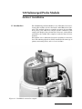
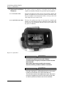
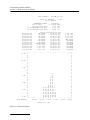
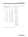
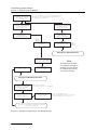
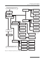
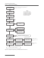
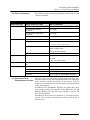
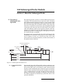
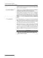
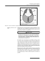
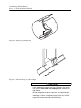
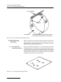
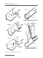
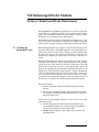
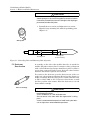
720 Submerged Probe Module Installation and Operation Guide Part #60-9003-368 Copyright © 1996. All rights reserved, Teledyne Isco Revision G, October 2013 Foreword This instruction manual is designed to help you gain a thorough understanding of the operation of the equipment. Teledyne Isco recommends that you read this manual completely before placing the equipment in service. Although Teledyne Isco designs reliability into all equipment, there is always the possibility of a malfunction. This manual may help in diagnosing and repairing the malfunction. If a problem persists, call or e-mail the Teledyne Isco Technical Service Department for assistance. Simple difficulties can often be diagnosed over the phone. If it is necessary to return the equipment to the factory for service, please follow the shipping instructions provided by the Customer Service Department, including the use of the Return Authorization Number specified. Be sure to include a note describing the malfunction. This will aid in the prompt repair and return of the equipment. Teledyne Isco welcomes suggestions that would improve the information presented in this manual or enhance the operation of the equipment itself. Teledyne Isco is continually improving its products and reserves the right to change product specifications, replacement parts, schematics, and instructions without notice. Contact Information Customer Service Phone: (800) 228-4373 (USA, Canada, Mexico) (402) 464-0231 (Outside North America) Fax: (402) 465-3022 Email: [email protected] Technical Support Phone: Email: Toll Free (866) 298-6174 (Samplers and Flow Meters) Toll Free (800) 775-2965 (Syringe Pumps and Liquid Chromatography) [email protected] Return equipment to: 4700 Superior Street, Lincoln, NE 68504-1398 Other Correspondence Mail to: P.O. Box 82531, Lincoln, NE 68501-2531 Email: [email protected] Revised September 2012 720 Submerged Probe Module Safety 720 Submerged Probe Module Safety General Warnings Hazard Severity Levels This product is often installed in confined spaces. Some examples of confined spaces are manholes, pipelines, digesters, and storage tanks. These spaces may become hazardous environments that can prove fatal for those unprepared. These spaces are governed by OSHA 1910.146 and require a permit before entering. This manual applies Hazard Severity Levels to the safety alerts, These three levels are described in the sample alerts below. CAUTION Cautions identify a potential hazard, which if not avoided, may result in minor or moderate injury. This category can also warn you of unsafe practices, or conditions that may cause property damage. WARNING Warnings identify a potentially hazardous condition, which if not avoided, could result in death or serious injury. DANGER DANGER – limited to the most extreme situations to identify an imminent hazard, which if not avoided, will result in death or serious injury. iii 720 Submerged Probe Module Safety Hazard Symbols The equipment and this manual use symbols used to warn of hazards. The symbols are explained below. Hazard Symbols Warnings and Cautions The exclamation point within the triangle is a warning sign alerting you of important instructions in the instrument’s technical reference manual. The lightning flash and arrowhead within the triangle is a warning sign alerting you of “dangerous voltage” inside the product. Pinch point. These symbols warn you that your fingers or hands will be seriously injured if you place them between the moving parts of the mechanism near these symbols. Symboles de sécurité Ce symbole signale l’existence d’instructions importantes relatives au produit dans ce manuel. Ce symbole signale la présence d’un danger d’électocution. Risque de pincement. Ces symboles vous avertit que les mains ou les doigts seront blessés sérieusement si vous les mettez entre les éléments en mouvement du mécanisme près de ces symboles Warnungen und Vorsichtshinweise Das Ausrufezeichen in Dreieck ist ein Warnzeichen, das Sie darauf aufmerksam macht, daß wichtige Anleitungen zu diesem Handbuch gehören. Der gepfeilte Blitz im Dreieck ist ein Warnzeichen, das Sei vor “gefährlichen Spannungen” im Inneren des Produkts warnt. Vorsicht Quetschgefahr! Dieses Symbol warnt vor einer unmittelbar drohenden Verletzungsgefahr für Finger und Hände, wenn diese zwischen die beweglichen Teile des gekennzeichneten Gerätes geraten. iv 720 Submerged Probe Module Table of Contents Section 1 Installation 1.1 1.2 1.3 1.4 1.5 1.6 Introduction . . . . . . . . . . . . . . . . . . . . . . . . . . . . . . . . . . . . . . . . . . . . . . . . . . . . . . . . Connecting to the Sampler . . . . . . . . . . . . . . . . . . . . . . . . . . . . . . . . . . . . . . . . . . . . Installation Checklist . . . . . . . . . . . . . . . . . . . . . . . . . . . . . . . . . . . . . . . . . . . . . . . . Determining the Probe Mounting Location . . . . . . . . . . . . . . . . . . . . . . . . . . . . . . . Considerations Before Installing . . . . . . . . . . . . . . . . . . . . . . . . . . . . . . . . . . . . . . . Maximum Installation Distances . . . . . . . . . . . . . . . . . . . . . . . . . . . . . . . . . . . . . . . 1.6.1 Extension Cables . . . . . . . . . . . . . . . . . . . . . . . . . . . . . . . . . . . . . . . . . . . . . . 1.6.2 Quick Disconnect Box . . . . . . . . . . . . . . . . . . . . . . . . . . . . . . . . . . . . . . . . . . 1-1 1-2 1-2 1-3 1-3 1-4 1-4 1-4 Section 2 Programming the Module 2.1 Module Screens . . . . . . . . . . . . . . . . . . . . . . . . . . . . . . . . . . . . . . . . . . . . . . . . . . . . . 2.2 Programmed Enable . . . . . . . . . . . . . . . . . . . . . . . . . . . . . . . . . . . . . . . . . . . . . . . . . 2.3 Data Storage . . . . . . . . . . . . . . . . . . . . . . . . . . . . . . . . . . . . . . . . . . . . . . . . . . . . . . . 2.3.1 Recovering Module Data . . . . . . . . . . . . . . . . . . . . . . . . . . . . . . . . . . . . . . . . 2.4 Flow Conversions . . . . . . . . . . . . . . . . . . . . . . . . . . . . . . . . . . . . . . . . . . . . . . . . . . . 2.5 Alternative Flow Measurement Systems. . . . . . . . . . . . . . . . . . . . . . . . . . . . . . . . . 2-1 2-1 2-1 2-1 2-7 2-7 Section 3 About the Submerged Probe 3.1 Principles of Submerged Probe Operation . . . . . . . . . . . . . . . . . . . . . . . . . . . . . . . . 3.1.1 Functionality Under Solids . . . . . . . . . . . . . . . . . . . . . . . . . . . . . . . . . . . . . . 3.1.2 Minimum Reliable Detection Level . . . . . . . . . . . . . . . . . . . . . . . . . . . . . . . 3.2 Submerged Probe Nose Sections . . . . . . . . . . . . . . . . . . . . . . . . . . . . . . . . . . . . . . . 3.2.1 Attaching the Nose Section . . . . . . . . . . . . . . . . . . . . . . . . . . . . . . . . . . . . . . 3-1 3-1 3-2 3-2 3-3 Section 4 Probe Installation Methods 4.1 General Mounting Considerations . . . . . . . . . . . . . . . . . . . . . . . . . . . . . . . . . . . . . . 4.2 Circular Channels . . . . . . . . . . . . . . . . . . . . . . . . . . . . . . . . . . . . . . . . . . . . . . . . . . . 4.2.1 Spring Rings . . . . . . . . . . . . . . . . . . . . . . . . . . . . . . . . . . . . . . . . . . . . . . . . . . 4.2.2 Scissors Rings . . . . . . . . . . . . . . . . . . . . . . . . . . . . . . . . . . . . . . . . . . . . . . . . 4.3 Other Mounting Techniques. . . . . . . . . . . . . . . . . . . . . . . . . . . . . . . . . . . . . . . . . . . 4.3.1 Rectangular and Trapezoidal Channels . . . . . . . . . . . . . . . . . . . . . . . . . . . . 4.3.2 Stilling Wells or Streams with Very Low Velocity . . . . . . . . . . . . . . . . . . . . 4.3.3 Securing Probe with a Weighted Plate . . . . . . . . . . . . . . . . . . . . . . . . . . . . . 4.3.4 Weirs and Flumes . . . . . . . . . . . . . . . . . . . . . . . . . . . . . . . . . . . . . . . . . . . . . 4.4 Completing the Probe Installation . . . . . . . . . . . . . . . . . . . . . . . . . . . . . . . . . . . . . . 4-1 4-2 4-2 4-5 4-6 4-6 4-7 4-7 4-7 4-9 Section 5 Module and Probe Maintenance 5.1 Cleaning the Submerged Probe . . . . . . . . . . . . . . . . . . . . . . . . . . . . . . . . . . . . . . . . 5-1 5.2 Desiccant Reactivation . . . . . . . . . . . . . . . . . . . . . . . . . . . . . . . . . . . . . . . . . . . . . . . 5-2 5.3 Flash Memory and Software Upgrades . . . . . . . . . . . . . . . . . . . . . . . . . . . . . . . . . . 5-3 v 720 Submerged Probe Module Table of Contents Appendix A Replacement Parts List Appendix B Technical Specifications Appendix C Material Safety Data Sheets C.1 Overview . . . . . . . . . . . . . . . . . . . . . . . . . . . . . . . . . . . . . . . . . . . . . . . . . . . . . . . . . . C-1 List of Figures 1-1 1-2 2-1 2-2 2-3 2-4 2-5 3-1 3-2 4-1 4-2 4-3 4-4 4-5 4-6 5-1 720 Module mounted on sampler . . . . . . . . . . . . . . . . . . . . . . . . . . . . . . . . . . . . . . Quick Disconnect Box (Cover Removed) . . . . . . . . . . . . . . . . . . . . . . . . . . . . . . . . . Summary Report . . . . . . . . . . . . . . . . . . . . . . . . . . . . . . . . . . . . . . . . . . . . . . . . . . . Combined Report (A) and Settings Report (B) . . . . . . . . . . . . . . . . . . . . . . . . . . . . Sampler Programming: 720 Module Screens . . . . . . . . . . . . . . . . . . . . . . . . . . . . . Sampler Programming: 720 Module Set Up Screens . . . . . . . . . . . . . . . . . . . . . . . Sampler Programming: 720 Module Quick View Screens . . . . . . . . . . . . . . . . . . . Submerged Probe Dimensions . . . . . . . . . . . . . . . . . . . . . . . . . . . . . . . . . . . . . . . . . Alignment of Grounding Point . . . . . . . . . . . . . . . . . . . . . . . . . . . . . . . . . . . . . . . . Sensor Installed on a Spring Ring . . . . . . . . . . . . . . . . . . . . . . . . . . . . . . . . . . . . . . Spring Ring Preparation . . . . . . . . . . . . . . . . . . . . . . . . . . . . . . . . . . . . . . . . . . . . . Mounting Ring in a Round Pipe . . . . . . . . . . . . . . . . . . . . . . . . . . . . . . . . . . . . . . . Universal Mounting Ring Adjustment . . . . . . . . . . . . . . . . . . . . . . . . . . . . . . . . . . Isco Rectangular Mounting Plate . . . . . . . . . . . . . . . . . . . . . . . . . . . . . . . . . . . . . . Typical Primary Device Installations . . . . . . . . . . . . . . . . . . . . . . . . . . . . . . . . . . . Grounding Point and Mounting Hole Alignment . . . . . . . . . . . . . . . . . . . . . . . . . . 1-1 1-4 2-2 2-3 2-4 2-5 2-6 3-1 3-3 4-3 4-4 4-4 4-6 4-6 4-8 5-2 List of Tables 2-1 4-1 A-1 B-1 B-2 vi Flow Conversion Methods . . . . . . . . . . . . . . . . . . . . . . . . . . . . . . . . . . . . . . . . . . . . 2-7 Locating the Head-Measuring Point . . . . . . . . . . . . . . . . . . . . . . . . . . . . . . . . . . . . 4-7 Replacement Parts and Accessories . . . . . . . . . . . . . . . . . . . . . . . . . . . . . . . . . . . . A-1 Technical Specifications for the 720 Submerged Probe Module . . . . . . . . . . . . . . B-1 Technical Specifications for the Submerged Probe . . . . . . . . . . . . . . . . . . . . . . . . B-1 720 Submerged Probe Module Section 1 Installation 1.1 Introduction The 720 Submerged Probe Module is one of Teledyne Isco’s interchangeable modules for the Avalanche and 6700 Series Samplers. The module enhances sampler operation by providing flow-pacing and additional sampler enable conditions. The sampler also displays the real-time level, flow rate, and total flow provided by the module. The sampler records the data for later analysis. The module uses a differential pressure transducer to measure level. The submerged probe is usually installed with some type of primary measuring device, such as a weir or flume. Figure 1-1 720 Module mounted on sampler 1-1 720 Submerged Probe Module Section 1 Installation 1.2 Connecting to the Sampler To install the module: 1. Turn the sampler off. 2. Remove the connector cap in the module bay and move it aside. 3. Slide the module into the bay. 4. Gently push against the module to be sure the connector is fully seated. To remove the module: 1. Turn the sampler off. 2. Press the silver button on top of the module and pull the module from the bay. 3. Replace the connector cap in the module bay. WARNING The module has not been approved for use in hazardous locations as defined by the National Electrical Code. Installation of this module in a hazardous location may cause fire or explosion resulting in death, personal injury, or property damage. Before installing any device in a dangerous location, review safety precautions in your sampler manual. Check applicable guidelines, codes, and regulations of federal, state, city, and county agencies. 1.3 Installation Checklist Installation Checklist: 1. Check the desiccant cartridge. Make sure the desiccant is active (blue or yellow in color) and remove the red cap. 2. Install the module and turn the sampler on. 3. Install the submerged probe in the channel. 4. Connect the submerged probe’s cable to the module. 5. Program the sampler and calibrate the module’s level reading. 6. Set up the sampler. See details in the sampler manual. 7. Run the program. Note You should install the module before turning the controller on. When the controller is turned on, it looks for a module. The controller will not recognize a newly installed module if it is not seen during this power-up routine. If you install a module while the controller is already on, turn the controller off and then on again to reconfigure the controller for use with the module. 1-2 720 Submerged Probe Module Section 1 Installation 1.4 Determining the Probe Mounting Location The location of the submerged probe depends on the method of level-to-flow rate conversion you are using. The probe is usually installed with some type of primary measuring device, such as a weir or flume. Most primary devices have a specific place for the head (level) measurement device. For example, the head measuring point of a weir is at least three times the expected maximum head upstream from the weir plate. For Parshall flumes, the measuring point is 1/3 of the way into the converging section. If you intend to measure flow by some other means, such as a gravity flow equation (Manning) or by calibrating a section of the flow channel (Data Points), you will have to determine the best location for the submerged probe. Select a location with hydraulic characteristics that are suitable for the method of level-to-flow rate conversion. For more details about the location of the head measuring point, refer to the Isco Open Channel Flow Measurement Handbook, or to information provided by the manufacturer of the primary device. For a list of available level-to-flow conversions, see Section 2, Table 2-1. 1.5 Considerations Before Installing The probe cable must be routed and secured so it does not collect debris. When installing the probe in a pipe or invert, mount the probe upstream from the outfall. Install the probe where liquid will cover the entire probe. The minimum level is approximately 0.1 foot (1.2 inch or 3.0 cm). The submerged probe can measure levels less than 0.08 feet (1 inch or 2.5 cm); however, accuracy in this range is not guaranteed. The level can be calibrated with the probe mounted at nearly any depth. Operation will be unaffected as long as the liquid covers the probe. This allows you to install the probe offset from the bottom, which has several advantages: • Avoidance of heavy concentrations of silt, sand, or other solids. • Aid in installation in narrow or hard-to-reach locations. • Maximization of level resolution over a specific level range. • Avoidance of obstructions in the flow stream. • The submerged probe can still measure level when covered with silt and sand, as long as pressure gets through. • If the level is a negative value, or if you need to toggle between positive and negative in the ADJUST LEVEL menu, press the "±" key before entering the numerical value. 1-3 720 Submerged Probe Module Section 1 Installation 1.6 Maximum Installation Distances For probe location at distances exceeding 25 feet from the sampler and module, Teledyne Isco provides special equipment. 1.6.1 Extension Cables To locate the probe more than 25 feet away from the sampler and module, use Teledyne Isco’s vented 25 or 50 foot extension cables. You can combine vented extension cables, as long as the total cable length does not exceed 75 feet. 1.6.2 Quick Disconnect Box To locate the probe more than 75 feet from the sampler and module, use the Submerged Probe Quick Disconnect Box. The box increases the maximum distance between the module and the probe to 1.000 feet. Figure 1-2 Quick Disconnect Box (Cover Removed) WARNING Mounting hardware may have sharp edges. Cuts and abrasions are possible. Injuries form hardware contaminated by sewage my also becom infected. To avoid these hazards: Wear leather gloves when handling the hardware. Clean the mounting hardware between installations. CAUTION Abusive handling will damage the pressure transducer inside the probe. Although the submerged probe will survive normal handling and installation, treat it with reasonable care. The vent tube inside the cable must remain open. Do not kink the cable, overtighten the plastic ties while securing the cable, or allow any moisture to enter the vent via the connector. 1-4 720 Submerged Probe Module Section 2 Programming the Module 2.1 Module Screens When the controller is configured with the module, it adds the necessary screens for programming. The screens appear on the following pages in Figures 2-3, 2-4, and 2-5. These figures outline the steps for module programming and calibration. For 6700 or 6712 programming and general programming information, see the sampler manual. Note An * (asterisk) appears next to a reading if the module was unable to take a reading. If an * appears, the reading displayed is the last available reading. See Table 2-1 for flow conversion types. 2.2 Programmed Enable When the 720 Module is installed, additional sampler enable options are available. If programmed for LEVEL ONLY, the option will be LEVEL. If programmed for FLOW METER, the options will be LEVEL and FLOW. For more information about programmed enables, see Sampler Enable in the sampler manual. 2.3 Data Storage When the sampler is configured for use with the module, a memory partition is reserved. The module readings are stored in this sampler memory partition. For more information on data storage and partition management, please refer to your 6700 series sampler instruction manual. 2.3.1 Recovering Module Data The stored module data can be collected or viewed as “reports.” Three of the sampler reports can contain module information. Please refer to your 6700 series sampler instruction manual for collecting and reading the reports. 2-1 720 Submerged Probe Module Section 2 Programming the Module Flow Summary - 14 JUN-02 (FR) Flow at "FACTORY " Site On 14-JUN-02 SUBMERGED PROBE: 638324458 Day's Flow: 0.678964 Mgal Average Flow Rate: 3.466 cfs 12:45 Maximum Flow Rate: 6.689 cfs 14:49 Minumum Flow Rate: 1.442 cfs 00:00-01:00: 01:00-02:00: 02:00-03:00: 03:00-04:00: 04:00-05:00: 05:00-06:00: 06:00-07:00: 07:00-08:00: 08:00-09:00: 09:00-10:00: 10:00-11:00: 11:00-12:00: Hourly Average Flow Rate: NO DATA 12:00-13:00: NO DATA 13:00-14:00: NO DATA 14:00-15:00: NO DATA 15:00-16:00: NO DATA 16:00-17:00: NO DATA 17:00-18:00: NO DATA 18:00-19:00: BEGIN DATA 19:00-20:00: 2.519 cfs 20:00-21:00: 2.747 cfs 21:00-22:00: 2.791 cfs 22:00-23:00: 3.456 cfs 23:00-24:00: * - - - + - - - + + I I I I 10.00 + I I I I 8.00 + I I I I 6.00 + I I I I 4.00 + I I I I # 2.00 + # I # I # I # I # 0.00 + # * - - - + - - - + Hour Ending: 04:00 08:00 12.00 - - + - - - + - - - + - - - + * + I I I I + I I I I + I I I # I # + # I # # I # # I # # I # # + # # I # # # I # # # I # # # # # # I # # # # # # + # # # # # # I # # # # # # # I # # # # # # # I # # # # # # # I # # # # # # # + - - + - - - + - - - + - - - + * 12:00 16:00 20:00 24:00 Units are 'cfs' Figure 2-1 Summary Report 2-2 5.385 cfs 6.651 cfs 2.591 cfs 1.593 cfs END DATA NO DATA NO DATA NO DATA NO DATA NO DATA NO DATA NO DATA 720 Submerged Probe Module Section 2 Programming the Module SAMPLER ID# 11343009 15:25 14 JUN 02 SUBMERGED PROBE: 638324458 *********** COMBINED RESULTS *********** SITE: FACTORY Program Started at 08:41 FR 14 JUN 02 Nominal Sample Volume = 200 ml SAMPLE 1 1 1 1 1 1 1 1 1 1 1 1 1 1 1 1 1 1 1 1 1 1 1 1 BOTTLE TIME 1 2 3 4 5 6 7 8 9 10 11 12 13 14 15 16 17 18 19 20 21 22 23 24 08:41 08:56 09:11 09:26 09:41 09:56 10:11 10:26 10:41 10:56 11:11 11:26 11:41 11:56 12:11 12:26 12:41 12:56 13:11 13:26 13:41 13:56 14:11 14:26 A FLOW RATE cfs TOTAL FLOW Mgal 2.495 2.576 2.666 2.773 2.773 2.798 2.798 2.798 2.751 2.773 2.798 3.728 3.728 3.728 3.728 5.273 5.239 6.651 6.651 6.651 6.651 6.651 3.404 3.425 0.000000 0.016941 0.034698 0.052914 0.071707 0.090520 0.109314 0.128112 0.146911 0.165698 0.184556 0.206933 0.232024 0.257108 0.282171 0.317318 0.352755 0.396903 0.441689 0.486476 0.531238 0.575999 0.611500 0.634426 SAMPLER ID# 11343009 15:25 15-SEP-03 *********** PROGRAM SETTINGS *********** ---------SITE DESCRIPTION: "FACTORY " ---------UNITS SELECTED: LENGTH: ft ---------UNITS SELECTED: FLOW RATE: cfs FLOW VOLUME: Mgal ---------SUBMERGED PROBE: WEIR 90 V-NOTCH ---------1 MINUTE DATA INTERVAL ---------24, 1000 ml BTLS 10 ft SUCTION LINE ---------PACING: TIME, EVERY 0 HOURS, 15 MINUTES ---------DISTRIBUTION: SEQUENTIAL 200 ml SAMPLES ---------5 MINUTE DELAY TO FIRST SAMPLE RUN PROGRAM ONCE --------------------------------------B Figure 2-2 Combined Report (A) and Settings Report (B) 2-3 720 Submerged Probe Module Section 2 Programming the Module MODULE INSERTED-DOWNLAD DATA NOW OR LOSE ALL DATA! DONE This screen appears only when a module has been switched or if the module was unplugged while the sampler was powered. Standard 6712 SAMPLER STANDARD PROGRAMMING For HELP at any screen press ? key Extended 6712 SAMPLER EXTENDED PROGRAMMING For HELP at any screen press ? key RUN PROGRAM VIEW REPORT OTHER FUNCTIONS RUN "EXTENDED 1' PROGRAM VIEW REPORT OTHER FUNCTIONS See sampler manual. SITE DESCRIPTION "FACTORY" CHANGE? YES NO PROGRAM NAME: "EXTENDED 1" SITE DESCRIPTION "FACTORY See sampler manual. See Figure 2-5, Quick View Screens. SELECT UNITS FOR FLOW RATE: gps gpm Mgd m3s m3h m3d Note: SELECT UNITS FOR FLOW VOLUME: cf gal Mgal m3 lit To program the module or run a program that requires a module, you must plug in the module before turning on the 6712 controller. cfs lps NO PROGRAM MODULE? YES NO YES See Figure 2-4, Module Set Up Screens. NEW MODULE SETUP -DOWNLOAD DATA NOW OR LOSE ALL DATA! DONE CURRENT LEVEL IS __.__ ft ADJUST LEVEL TO __.__ ft This screen appears only when a selection is changed. __.__ ft ARE YOU SURE? YES NO Continue with sampler programming sequence (see sampler manual). Figure 2-3 Sampler Programming: 720 Module Screens 2-4 This screen appears only when the adjustment differs from the current reading by more than 0.5 ft. 720 Submerged Probe Module Section 2 Programming the Module Continued from Figure 2-3 or 2-5. V-NOTCH RECTANGULAR CIPOLLETTI V-NOTCH WEIR ANGLE: 120 90 60 45 30 22.5 MODE OF OPERATION: FLOWMETER LEVEL ONLY END CONTRACTIONS ON RECTANGULAR WEIR? YES NO Weir WEIR FLUME EQUATION DATA POINTS MANNING ENTER CREST LENGTH: _.__ ft (min, max) Flume PALMER-BOWLUS PARSHALL TRAPEZOIDAL H EDIT DATA POINTS CLEAR DATA SET SELECT NEW SET CHANGE NAME PALMER-BOWLUS SIZE: 4" 6" 8" 10" 12" 15" 18" 21" 24" 27" 30" 48" (ft, cfs) 1. (____.____) 2. (____,____) 3. (____,____) PARSHALL SIZE: 1" 2" 3" 6" 9" 1' 1.5' 2' 3' 4' 5' 6' 8' 10' 12' TRAPEZOIDAL SIZE: 2" 45˚ WSC 12" 45˚ SRCRC LG 60˚ V PLEASE WAIT! ...SORTING DATA CLEAR DATA SET! ARE YOU SURE YES NO CURRENT LEVEL IS __.__ft ADJUST LEVEL TO __.__ft "DATA "DATA "DATA "DATA __.__ft ARE YOU SURE? YES NO SET SET SET SET H FLUME SIZE: 0.5' 0.75' 1.0' 1.5' 2.0' 2.5' 3.0' 4.5' 1" 2" 3" 4" DATA SET __________ ABCDEFGHIJKLMNOPQRST UVWXYZ -&"0123456789 BACKUP DONE INVALID ENTRY! ...DUPLICATE DEPTH Only in the case of step repetition. Stop SAVE CHANGES? YES NO Manning ROUND PIPE U-CHANNEL RECTANGULAR CHANNEL TRAPEZOIDAL CHANNEL Continued in Figure 2-3 or 2-5. ROUND PIPE SLOPE= _.____ ROUGHNESS= _.___ ROUND PIPE DIAMETER = _.___ft U-CHANNEL SLOPE = _.____ ROUGHNESS= _.___ U-CHANNEL WIDTH = _.___ft RECTANGULAR CHANNEL SLOPE = _.____ ROUGHNESS= _.___ RECTANGULAR CHANNEL TRAPEZOIDAL CHANNEL SLOPE = _.____ ROUGHNESS= _.___ TRAPEZOIDAL CHANNEL TOP WIDTH = _.___ft BOTTOM = _.___ft HEIGHT = __.__ft WIDTH = _.___ft Figure 2-4 Sampler Programming: 720 Module Set Up Screens 2-5 720 Submerged Probe Module Section 2 Programming the Module MODULE INSERTED-DOWNLOAD DATA NOW OR LOSE ALL DATA! DONE This screen appears only when a module has been switched or if the module was unplugged while the sampler was powered. Note: 6712 SAMPLER EXTENDED PROGRAMMING For HELP at any screen press ? key To program the module or run a program that requires a module, you must plug in the module before turning on the 6712 controller. RUN "EXTENDED 1" PROGRAM VIEW REPORT OTHER FUNCTIONS PROGRAM NAME: "EXTENDED 1" SITE DESCRIPTION "FACTORY UNITS SELECTED: LENGTH: ft UNITS SELECTED: FLOW RATE: cfs FLOW VOLUME:Mgal See sampler manual. SELECT UNITS FOR LENGTH: ft m SELECT UNITS FOR FLOW RATE: cfs gps gpm Mgd lps m3s m3h m3d SELECT UNITS FOR FLOW VOLUME: cf gal Mgal m3 lit SUBMERGED PROBE: WEIR 90˚ V-NOTCH See Figure 2-5, Module Set Up Screens. CURRENT LEVEL IS _.___ft CURRENT LEVEL IS __.__ ft ADJUST LEVEL TO __.__ ft __.__ ft ARE YOU SURE? YES NO __ MINUTE DATA INTERVAL DATA STORAGE INTERVAL IN MINUTES: 1 2 5 10 15 30 INTERVAL CHANGED -DOWNLOAD DATA NOW OR LOSE ALL DATA! DONE Continue with the sampler programming sequence (see sampler manual). Figure 2-5 Sampler Programming: 720 Module Quick View Screens 2-6 Only appears when adjustment differs from current reading by more than 0.5 ft. Only appears when data storage interval is changed. 720 Submerged Probe Module Section 2 Programming the Module 2.4 Flow Conversions The following table contains programming information for each conversion method. Table 2-1 Flow Conversion Methods Conversion Type Device, Formula, or Table Size or Parameters Weir V- Notch Weir 22.5, 30, 45, 60, 90, 120 degrees. Rectangular Weir with End Contractions Crest length. Rectangular Weir without End Contractions Crest length. Cipoletti Weir Crest length. Palmer-Bowlus Flume 4, 6, 8, 10, 12, 15, 18, 21, 24, 27, 30, 48 inches. Parshall Flume 1, 2, 3, 6, 9 inches. Flume 1, 1.5, 2, 3, 4, 5, 6, 8, 10, 12 feet. Trapezoidal Flume Large 60-degree V. 2-inch, 45-degree WSC. 12-inch, 45-degree SRCRC. “H” Flume Equation b+c Q=axH 0.5, 0.75, 1, 1.5, 2, 2.5, 3, 4.5 feet. x Hd Q = flow H = head a, b, c, & d = entered values Data Points User-developed tables for level-to-flow rate. 3 to 50 data points. Manning Equation Round Pipe Slope, Roughness, Diameter. U-Channel Pipe Slope, Roughness, Width. Rectangular Pipe Slope, Roughness, Width. Trapezoidal Slope, Roughness, Bottom Width, Top Width. 2.5 Alternative Flow Measurement Systems Because of the characteristics of submerged probe flow measurement, there may be some installations where the submerged probe method is either unreliable or inaccurate. In these instances, it is worthwhile to consider using an alternate method of flow measurement. In addition to the 720 Module, Teledyne Isco offers three other types of plug-and-play flow modules in the 700 Series: the 730 Bubbler Module, the 710 Ultrasonic Module, and the 750 Area-Velocity Module. Information about these flow modules is available from the factory. Call for more information or visit our Web site at www.isco.com. 2-7 720 Submerged Probe Module Section 2 Programming the Module 2-8 720 Submerged Probe Module Section 3 About the Submerged Probe 3.1 Principles of Submerged Probe Operation The submerged probe contains an internal differential pressure transducer. The transducer detects pressure with a stainless steel diaphragm that transfers pressure to a piezo-resistive disk. The outer face of the diaphragm is exposed to the pressure of the flow stream through ports around the outside of the probe. The inner face is exposed, or referenced, to the atmosphere through an internal vent tube that runs the full length of the probe’s cable. The difference between the pressures exerted on the diaphragm is the hydrostatic pressure. The transducer converts the hydrostatic pressure to analog signals. The signals are sent to the module through an amplifier. Because pressure is proportional to the level of the stream, the 720 Module can convert the analog signal to level readings. The level readings, in turn, are converted to flow rates with level-to-flow-rate conversion formulas, or tables characteristic of the primary device at the site. Bore 0.437" X 0.330" Deep (1.11 X 0.838 cm) 0.141" Dia. Thru. (0.358 cm) 0.812" (2.06 cm) Liquid Ports 0.670" (1.70 cm) 0.875" (2.22 cm) 3.625" (9.21 cm) 7.249" (18.42 cm) 9.38" (23.82 cm) Figure 3-1 Submerged Probe Dimensions 3.1.1 Functionality Under Solids Consequently, the probe will normally continue to function even when covered with several inches of silt or sand. Note however, that porous solids, such as wood chips or other organic material that may swell considerably when soaked in water, can interfere with the correct operation of the pressure transducer. In extreme cases, swelling material can put enough pressure on the diaphragm of the pressure transducer to deform it. This will ruin the submerged probe by introducing a permanent offset to the pressure transducer. 3-1 720 Submerged Probe Module Section 3 About the Submerged Probe Note Always install the probe where it will be under water, even if only an inch or so. The probe cannot measure levels that fall below its location in the stream. 3.1.2 Minimum Reliable Detection Level It is important to note that there is a practical minimum water level below which the submerged probe cannot reliably measure level. This minimum level is approximately equal to the height of the probe body, 0.1 ft. (1.3 in. or 0.030 m). Liquid levels lower than this will be below the levels used to calibrate the sensor. The submerged probe level sensor will continue to measure levels less than 0.1 ft.; however, the accuracy of the measurement in this range is not guaranteed. Consequently, you should always use the submerged probe with caution in very low flow situations. 3.2 Submerged Probe Nose Sections Standard Nose Section Slanted Nose Section Teledyne Isco provides three nose sections, each designed for specific flow stream conditions. A complete list of nose sections and their part numbers can be found in Appendix A. Standard Nose Section – The standard nose section works in any flow stream and will be installed on your probe unless otherwise specified in your order. It is particularly well suited for flow streams with high velocities because its shape overcomes hydraulic problems that develop in these flow streams. At velocities exceeding 5 feet per second (1.5 meters per second), localized low-pressure areas form near the submerged probe, which can result in erroneous level readings. The length of the nose section (3.87 inches or 9.84 cm) minimizes low-pressure areas by allowing the flow stream to stabilize before it reaches the probe’s entrance ports. Slanted Nose Section – Under certain conditions - low flow rates in debris-laden small sewers, for example - the submerged probe may catch and retain the debris, obstructing the flow stream and causing erroneous level readings. To avoid this problem, use the slanted nose section. This nose section has a slanted leading edge that tends to shed debris more readily than the standard nose section. Use the slanted nose section with caution, however, Under conditions of low flow and high velocity, the slanted nose section may induce a hydraulic “jump” in the flow stream that can cause erroneous level readings. Flume Cap 3-2 Flume Cap – The flume cap is a small, blunt cap that replaces the nose section. Most flume manufacturers can supply flumes with a small cavity to accept an Isco probe. The probe cap protects the transducer while minimizing the total length. 720 Submerged Probe Module Section 3 About the Submerged Probe 3.2.1 Attaching the Nose Section After cleaning, reinstall the nose section and tighten the screws. The mounting hole must be aligned with the grounding point. Figure 3-2 Alignment of Grounding Point 3-3 720 Submerged Probe Module Section 3 About the Submerged Probe 3-4 720 Submerged Probe Module Section 4 Probe Installation Methods The following sections describe installation of the submerged probe. The first section presents general mounting considerations common to all submerged probe mounting techniques. The following sections describe probe installation using the two systems available for mounting the submerged probe in pipes or round-bottomed flow streams. For pipes up to 15 inches (38.1 cm) in diameter, spring stainless steel self-expanding mounting rings are available. For pipes larger than 15 inches in diameter, Teledyne Isco offers the Scissors Ring. For use in similarly-sized manhole inverts, you can use the base and extension sections of the Scissors Ring without the scissors section. The straps are held in place by studs installed in the wall of the flow stream using a power-activated stud gun. Submerged probes are also installed in primary measuring devices. 4.1 General Mounting Considerations The location of the probe in the stream is usually dependent on the flow rate conversion used. For example, if you are using the probe with a primary measuring device (weir or flume), there is a specific location for the probe with each primary device. The Isco Open Channel Flow Measurement Handbook provides much useful information in this regard. If you want to measure flow using a gravity flow equation, such as the Manning equation, you will generally install the probe in the entrance (upstream) pipe of a manhole. If you want to measure flow by calibrating a manhole invert, you would probably locate the probe directly in the manhole invert. In any case, you must determine the appropriate location of the probe, based on the hydraulic characteristics of the site and the method of level-to-flow rate conversion used. You do not have to install the submerged probe at the bottom of the flow stream. Although the bottom is the normal position, the Parameter to Adjust step in the program allows you to mount the probe at any vertical location in the stream, and then adjust the indicated level to match the actual level. (The 720 can indicate negative levels.) A location other than the bottom of the flow stream may be useful for various reasons: to avoid heavy concentrations of silt, sand, or other solids; to make installation easier in tight locations; to maximize level resolution over a specific level range; to avoid hydraulic obstructions in the flow stream, etc. The probe has several ports through which liquid enters the body to contact the pressure transducer. The only way for the probe to malfunction is for all the ports to be completely blocked. Most 4-1 720 Submerged Probe Module Section 4 Probe Installation Methods substances likely to cover the probe are somewhat porous, which still allows the hydrostatic pressure of the flow stream over the probe to reach the transducer. 4.2 Circular Channels Consult your Isco Mounting Rings Installation and Operation Guide for detailed hardware information. The following sections describe sensor installation using the two options available for mounting sensors in pipes or round-bottomed flow streams. For pipes up to 15" (38.1 cm) in diameter, stainless steel self-expanding mounting rings (Spring Rings) are available. For pipes larger than 15" in diameter, Teledyne Isco offers the Scissors Rings (Universal Mounting Rings). 4.2.1 Spring Rings To install a spring ring, you compress the ring, slip it inside the pipe, and then allow it to spring out to contact the inside diameter of the pipe. The inherent outward spring force of the ring firmly secures it in place. A typical self-expanding mounting ring (with a probe mounted on it) is shown in Figure 4-1. These mounting rings are available for use in pipes with inside diameters of 6" (15.2 cm), 8" (20.3 cm), 10" (25.4 cm), 12" (30.5 cm), and 15" (38.1 cm). The Teledyne Isco part numbers for the various size mounting rings available are listed in Appendix B. These part numbers include not only the ring, but also the miscellaneous hardware necessary to mount the sensor on the ring. CAUTION Always wear leather gloves when handling the rings (either type). The metal is finished, but there is still a possibility of cutting your hands on the edges. 4-2 720 Submerged Probe Module Section 4 Probe Installation Methods Compress ring into gap to install in pipe, then... ...outward force of ring against pipe wall holds ring in place inside pipe. Figure 4-1 Sensor Installed on a Spring Ring Attaching the Sensor to the Ring Attach the probe to the ring either by using two 4-40 x 3/16" countersink screws or by snapping the optional probe carrier to the ring. This second method of attaching the sensor allows for easy removal in case service is needed later. CAUTION Make sure the slots on the probe carrier are completely pressed onto the tabs on the ring. This is particularly important where there is any possibility of reverse flows, or where flows are of high velocity. If the probe is not fully pressed onto the mounting ring tabs, it might come loose in the stream, and could possibly be damaged or lost. To complete the sensor-spring ring assembly procedure, attach the sensor cable to the downstream edge of the ring. Follow the cable routing shown in Figure 4-1. Other routing directions may affect measurement accuracy. The cable can actually create a stilling well downstream from the sensor, causing the level to read low. Use the self-locking plastic ties supplied with the ring. Install the ring in the pipe by compressing it. Press inward on both sides and slide the ring into the pipe. Route the sensor cable out of the stream and secure it in position by placing the ties through the holes in the mounting ring and then locking them around the cable, as shown. To prevent debris from catching on the cable, it is important to attach the cable to the mounting ring so it offers as little resistance to the flow as possible. 4-3 720 Submerged Probe Module Section 4 Probe Installation Methods Figure 4-2 Spring Ring Preparation Flo w Figure 4-3 Mounting Ring in a Round Pipe CAUTION Make sure the sensor cable is securely fastened along the back (downstream) edge of the ring. Otherwise, the sensor may provide inaccurate level readings under conditions of high velocity. Do not overtighten the plastic cable ties; they should be tightened just enough to secure the cable in place, without greatly indenting the cable. Overtightening the plastic ties may collapse the reference tube in the cable, blocking it. 4-4 720 Submerged Probe Module Section 4 Probe Installation Methods The spring ring may need anchoring. Under conditions of high velocity (greater than 5 feet per second or 1.5 meters per second), the ring may not have sufficient outward spring force to maintain a tight fit inside the pipe. The ring may start to lift off the bottom of the pipe in a waving fashion, or may even be carried downstream. This problem is more prevalent in the larger diameter pipes (10", 12", and 15", and in pipes with smooth inside surfaces, such as plastic pipes). If any of these conditions are present, or if movement of the mounting ring is detected or suspected, you must anchor the ring in place. You can do this by setting screws through the ring into the pipe, or by other appropriate means. If there is a problem with the smaller diameter rings, it may be sufficient to simply increase the outward spring force of the ring by bending it into a less round configuration. 4.2.2 Scissors Rings For pipes larger than 15" in diameter, Teledyne Isco offers the adjustable Scissors Ring (also known as the Universal Mounting Ring). This device consists of two or more metal strips that lock together with tabs to form a single assembly. There is a base section where the sensors are mounted, one or more extension sections (usually), and a scissors section at the top that expands the entire assembly and tightens it inside the pipe. The scissors mechanism includes a long screw that increases the width as it is tightened. The assembled rings fit pipe diameters from 16" to 80". Secure the unit in place by tightening the scissors mechanism with a 5/8" socket wrench or other suitable tool. Ring sections are .040" thick half-hard 301 stainless steel sheet. All other parts are also stainless steel, except for the plastic cable ties in the hardware kit. Each extension, 1, 2, 3, and 4, adds 9.0", 21.5", 31.5", or 41.5", respectively, to the circumference of the ring. Used alone, the base section fits pipe that is approximately 16" to 18" in diameter. The 9.0" (the smallest) extension exists so that in larger pipe sizes, where large variations in circumference can occur, you can use one or two of these extensions to take up or remove slack, to bring the scissors mechanism into a position where it can be effectively tightened. Mounting ring kits are available for different pipe sizes. A kit is also available for partial pipe applications (see your Isco Mounting Rings Installation and Operation Guide). For a listing of part numbers and ordering information, see Appendix B. CAUTION Do not overtighten the plastic cable ties; they should be tightened just enough to secure the cable in place, without greatly indenting the cable. Overtightening the plastic ties may collapse the reference tube in the cable, blocking it. 4-5 720 Submerged Probe Module Section 4 Probe Installation Methods Scissors Assembly Extensions Base Section Tightening the scissors assembly expands the ring to press firmly against the pipe wall, securing the ring. Figure 4-4 Universal Mounting Ring Adjustment 4.3 Other Mounting Techniques 4.3.1 Rectangular and Trapezoidal Channels Many installations require mounting methods other than mounting rings. Some alternative mounting methods are described below. Contact Teledyne Isco for assistance in determining your specific installation needs. A flat, anchored mounting plate is a common mounting choice for installing sensors in rectangular or trapezoidal channels. You can also install the probe in rectangular channels by bending a mounting ring to fit the channel. Attach the ring to the channel wall with studs. Consult your Isco Mounting Rings Installation and Operation Guide for more information. Figure 4-5 Isco Rectangular Mounting Plate 4-6 720 Submerged Probe Module Section 4 Probe Installation Methods 4.3.2 Stilling Wells or Streams with Very Low Velocity In flow streams with a minimal flow velocity or in a stilling well, simply attach the probe to a weighted plate and submerge the plate in the stream or stilling well. 4.3.3 Securing Probe with a Weighted Plate In situations with a minimal flow velocity (for example, in a stilling well), you can simply attach the probe to a weighted plate and submerge it in the flow. 4.3.4 Weirs and Flumes The 720 is generally used with some type of primary measuring device, such as a weir or flume. The placement of the submerged probe in the primary device is determined by the type of primary device. You can use one of Isco’s mounting rings to install the probe in many weirs and flumes. If the mounting ring are not suitable, you must build your own mounting hardware. Figure 3-1 shows the dimensions of the probe for your reference when building your own hardware. Figure 4-6 shows the probe installed in several primary devices. Certain flume manufacturers produce flumes with built-in cavities for Isco’s submerged probe. Contact the flume manufacturer for details on the special flumes. Note Always install the submerged probe pointing toward normal flow at the head-measuring point of the device. The location of the measuring point varies with each device. Refer to Table 4-1 or to the Isco Open Channel Flow Measurement Handbook. Table 4-1 Locating the Head-Measuring Point Device Head-Measuring Point Weirs Upstream from the weir plate by at least 3 times the maximum head. Parshall Flumes 1 Palmer-Bowlus Flumes Upstream from the flume entrance by half the pipe diameter. /3 of the way into the converging section. Note When installing the probe with custom hardware, remember to attach the probe securely to the side or bottom of the flow stream and tie the cable down so that it does not collect debris. For many primary measuring device installations, the submerged probe mounting rings or base sections discussed previously may be used to mount the probe at the appropriate location. In many installations, though, the mounting rings or bases may not be suitable. 4-7 720 Submerged Probe Module Section 4 Probe Installation Methods Weir Round Pipe Sensor Mounting Plate Spring Ring Round Pipe: Probe installed from above, outside of manhole, by using Street Level Installation System. Street Level Installation Components 1. Handle 2. Ring Palmer-Bowlus Flume Base Bottom Assembly Parshall Flume Round Pipe Probe Mounted in Recess Figure 4-6 Typical Primary Device Installations 4-8 Contact the factory or your Teledyne Isco Representative for additional information about the Street Level Installation system. 720 Submerged Probe Module Section 4 Probe Installation Methods Mounting hardware may have to be fabricated locally to allow the level sensor to be mounted at the correct location in the primary device. The only requirements for custom mounting hardware are: • The probe must be securely attached to the side or bottom of the flow stream. • The cable must be tied down and led out of the flow stream in an orderly manner. • The hardware be made from corrosion-resistant materials. It should be noted that the mounting rings may be used to install the probe in rectangular channels by simply putting right angle bends in them at the appropriate locations. It should be noted that certain flume manufacturers produce flumes with built-in cavities designed specifically for use with Isco submerged probe level sensors. Typically, these are Parshall or Palmer-Bowlus flumes. Contact the manufacturer for details on these flumes. 4.4 Completing the Probe Installation The submerged probe installation is finished by coiling any excess sensor cable and securing it using cable clamps or other means. The reference tube inside the cable can be restricted or blocked if the cable is kinked, sharply bent, or otherwise pinched. The probe cable should be handled and mounted with care. Also, if there is any appreciable distance between the point where the probe cable leaves the mounting apparatus and the location of the flow meter, be sure to attach the cable to the flow stream wall to prevent it from vibrating, moving around, tangling, or possibly collecting debris. CAUTION Under no circumstances should you leave any extra length of sensor cable dangling freely in the flow stream where it could trap debris or become tangled. Use gloves and eye protection when assembling and installing the rings in a pipe. Though deburred, the edges of the stainless steel can cut if improperly handled. Please read the information on how best to install this device. Observe general safety procedures when entering any manhole. See “General Safety Procedures” in the back of the manual for more information on general hazards and necessary precautions. 4-9 720 Submerged Probe Module Section 4 Probe Installation Methods 4-10 720 Submerged Probe Module Section 5 Module and Probe Maintenance The 720 Module and Submerged Probe have no user-serviceable parts. They are completely sealed to protect the internal components. If you think the module or probe requires repair, contact Teledyne Isco’s Customer Service Department. The Submerged Probe will provide reliable readings over a long service life with a minimum of maintenance. Maintaining the probe requires regular cleaning and keeping the desiccant active. 5.1 Cleaning the Submerged Probe The submerged probe may require occasional cleaning. Because the probe body offers a streamlined profile to the flow, solid materials rarely collect on its surface. However, remove debris from the flow stream near the probe periodically to maintain the hydrostatic conditions on which the level-to-flow conversion is based. The probe functions even when covered with silt, sand, or other solid materials. However, organic materials may become jammed inside the probe. This material swells as it becomes saturated with water and exerts pressure on the diaphragm. This can damage the diaphragm, permanently disabling the probe. If all liquid ports in the probe become blocked, or if the diaphragm cavity is packed with material, clean the probe. This not only protects the probe from damage, but ensures that the probe responds to the hydrostatic pressure above the probe instead of the pressure created by the swollen material inside the probe. To clean the probe: 1. Remove the probe and its mounting ring from the flow stream. 2. Scrape any accumulated solids off the exterior of the probe. Use a brush and flowing water. Gently flush the cavities of the probe with water. If the ports are thoroughly blocked or if you need to clean the probe for storage: 1. Remove the probe nose section by unscrewing the two screws which hold the nose section in place and pull the nose section straight out of the probe body. 2. Gently flush the probe cavity with water to remove any solid materials. 5-1 720 Submerged Probe Module Section 5 Module and Probe Maintenance CAUTION Do not remove the warning disk at any time. The stainless steel diaphragm on the face of the probe’s pressure transducer is extremely vulnerable to pressure. Damage to the diaphragm permanently disables the probe. DO NOT TOUCH DIAPHRAGM BELOW 3. Reinstall the nose section and tighten the two screws. Align the large mounting hole with the grounding point (Figure 5-1). Warning Disk Grounding Point Mounting Hole (Countersunk Side) Figure 5-1 Grounding Point and Mounting Hole Alignment 5.2 Desiccant Reactivation A cartridge on the side of the module dries the air inside the module and probe reference line. It contains a silica gel desiccant with a color indicator that changes from blue to pink, or yellow to green when saturated. Pink or green desiccant cannot remove moisture and must be replaced or reactivated. To reactivate the desiccant, pour the desiccant out of the cartridge into a heat-resistant container. Never heat the plastic cartridge; it will melt. Heat the silica gel in a vented convection oven at 212° to 350° F (100° to 175° C) for two to three hours, or until the blue or yellow color returns. Allow the desiccant to cool and then refill the cartridge. Desiccant Cartridge CAUTION Desiccant may produce irritating fumes when heated. Observe the following precautions: •Use a vented oven in a well-ventilated room. •Do not remain in the room while the regeneration is taking place. •Use the recommended temperature. Avoid heating the desiccant at higher than recommended temperatures. 5-2 720 Submerged Probe Module Section 5 Module and Probe Maintenance The desiccant’s ability to remove moisture may lessen with each saturation/reactivation cycle, resulting in a need for more frequent service. After several cycles, the desiccant may no longer be effective as it saturates too quickly. At this point, replace the desiccant. The sponge filters in the end caps keep small pieces of the desiccant material from falling out of the cartridge. When the filters become soiled, wash with dish soap and water, then allow to dry. 5.3 Flash Memory and Software Upgrades The module has Flash memory to store its software. With Flash technology, you can upgrade your module’s software without sending it back to the factory or replacing a chip. To update the module software, install the module in a 6700 series sampler. Then connect the sampler power source and turn the sampler on. Connect the sampler to a computer and follow the instructions received with your Flash Update program. 5-3 720 Submerged Probe Module Section 5 Module and Probe Maintenance 5-4 720 Submerged Probe Module Appendix A Replacement Parts List The following table contains information about replacement parts and accessories. Replacement parts and accessories can be purchased by contacting Teledyne Isco’s Customer Service Department. Table A-1 Replacement Parts and Accessories Part Description Part Number 720 Submerged Probe Module 60-9004-030 Submerged Probe 10’ range with 25’ cable 60-3224-002 720 Submerged Probe Instruction Manual 60-9003-368 Sensor Carrier 60-3204-005 Isco Open Channel Flow Measurement Handbook 60-3003-041 Spring Ring - 6" Dia. 68-3200-007 Spring Ring - 8" Dia. 68-3200-008 Spring Ring - 10" Dia. 68-3200-009 Spring Ring - 12" Dia. 68-3200-010 Spring Ring - 15" Dia. 68-3200-011 (Each spring ring includes plastic ties to fasten the probe cable.) Scissors Ring for 16" - 23" Pipe 68-3000-042 Scissors Ring for 16" - 36" Pipe 68-3000-043 Scissors Ring for 39" - 43" Pipe 68-3000-044 Scissors Ring for 45" - 49" Pipe 68-3000-045 Scissors Ring for 58 to 62" Pipe 68-3000-046 Scissors Ring for 72" Pipe 68-3000-047 Scissors Ring for 16" - 80" Pipe 68-3000-048 (Each scissors ring includes a base section, scissors mechanism, extensions, plastic ties, and instructions) Base Section (Includes plastic ties and instructions) 60-3004-169 Scissors Mechanism 60-3004-170 Street Level Installation System Multi-Section Pole. 60-3204-012 (Includes instruction manual. To complete your system, you must also order a Street Level Mounting Ring.) Street Level Mounting Ring for 6“ diameter pipe 60-3204-014 Street Level Mounting Ring for 8“ diameter pipe 60-3204-015 A-1 720 Submerged Probe Module Appendix A Replacement Parts List Table A-1 Replacement Parts and Accessories (Continued) Part Description Part Number Street Level Mounting Ring for 10“ diameter pipe 60-3204-016 Street Level Mounting Ring for 12“ diameter pipe 60-3204-017 Street Level Mounting Ring for 15“ diameter pipe 60-3204-018 Sensor Mounting Plate (includes plastic ties and instructions) 60-3253-077 Desiccant Cartridge Assy 60-9004-105 1-lb Refill Bottle of Desiccant 60-2004-233 Quick Disconnect Box 60-3224-003 Standard Nose Section 60-2503-086 Slanted Nose Section 60-2503-097 Flume Probe Cap 60-2503-105 A-2 720 Submerged Probe Module Appendix B Technical Specifications The following tables contain information covering the technical specifications of the 720 Module and Submerged Probes, including operating and storage temperatures, physical dimensions and weights, operating method and ranges, and memory capacity. General Notes: 1. All weights may vary ± 0.2 lb (± 0.1 kg). 2. All lengths may vary ± 0.23 inch (± 0.64 cm). Table B-1 Technical Specifications for the 720 Submerged Probe Module Operating Temperature 0° to 140° F (-18° to 60° C) Storage Temperature -40° to 140° F (-40° to 60° C) Power Provided by the sampler Level Resolution 0.002 ft (0.0006 m) Memory Nonvolatile programmable Flash. Can be field updated through the sampler. Readings Programmable through sampler at 1, 2, 5, 10, 15, and 30 minute intervals. All readings are stored in the sampler. Weight 0.9 lbs (0.4 kg) Dimensions 4.9 x 5.7 x 2.0 inches (12.4 x 14.5 x 5.1 cm) Material Polystyrene Enclosure NEMA 4X and 6, IP67 Table B-2 Technical Specifications for the Submerged Probe Operating Temperature 32° to 160° F (0° to 71° C) Storage Temperature -40° to 160° F (-40° to 71° C) Level Measurement Method Submerged pressure transducer mounted in the flow stream. Transducer Type Differential linear integrated circuit pressure transducer. Level Measurement Range 0.1 ft to 10 ft (0.03 m to 3.05 m) Maximum Allowable Level 20 ft (6.1 m) Level Measurement Accuracy 0.033 to 5.0 ft: ±0.008 ft/ft >5.0 ft: ±0.012 ft/ft (0.01 to 1.52 m: (>1.52 m: ±0.008 m/m) ±0.012 m/m) @ 77° F (25° C). Includes non-linearity, repeatability, and hysteresis, but does not include temperature coefficient. Compensated Temperature Range 32° to 100° F (0° to 38° C) B-1 720 Submerged Probe Module Appendix B Technical Specifications Table B-2 Technical Specifications for the Submerged Probe (Continued) Temperature Coefficient 0.1 to 4.0 ft: ± 0.005 ft/°F (0.03 to 1.22 m: ± 0.0027 m/°C) 4.0 to 10.0 ft: ± 0.007 ft/°F (1.22 to 3.05 m: ± 0.0038 m/°C) Maximum error over compensated temperature range, per degree of temperature change. Sensor Dimensions Diameter: 0.875 inches (2.2 cm) Length: 5.5 inches (14.0 cm) without nose 9.5 inches (24.1 cm) with standard nose Frontal Area: 0.601 in² (3.88 cm²) Amplifier Box Watertight enclosure Cable Length: 25 feet (7.6 m) from sensor to amplifier box Weight 3 lbs (1.4 kg) Entire probe and cable Materials Probe Body: CPVC Transducer Diaphragm: Type 316 stainless steel Cable: PVC B-2 720 Submerged Probe Module Appendix C Material Safety Data Sheets C.1 Overview This appendix provides Material Safety Data Sheets for the desiccant used in the 720 Module. Teledyne Isco cannot guarantee the accuracy of the data. Specific questions regarding the use and handling of the products should be directed to the manufacturer listed on the MSDS. C-1 '4 ,"'&@5 < &$)("/'4 "!"/$$'/ &","& "$"$ -#$#-"'/*& &","& "$"$ "&#-'''(# -,+" )%%!&/ L@6GCF6AHA6GE?? L@6GCF6AHA6GE?? &,**$'$'*('*,"'& G??-++/13-",@?@ *#" 3 E??EG $(!'&5 05 L@6GCF6AHA6GE?? L@6GCF6AHA6GE?@ ,"'&A5 < )"&'/@BCB8HG8A3FF8?H8G $!)!&$&")!/"A9&ALA?@CC ,"'&B5 $(#(!!((' #!($#/1-+*1&++&"**",,"'&,'%-'-+%%*&+3&'+&,!*',61%(,'%+ %1"&$-'- !"& 3+'*,!*',3&/!2"& 6 #'($#/'.*+,+0(,6 #$#((/1-+"**",,"'&/",!*1&++&*+"'&6 -$#((/1-+"**",,"'&3*&++&("&6 &$#,%$')&/(,0('+-*%1-++1%(,'%++"%"$*,',!'+$"+,'*-,,+6 1&,!,"%'*(!'-++"$"'+&',(*'-+"$"'+"+6 ,"'&C5 -$#((/!#'*&*%'.&1'&,,$&++6 &+''&,,3"%%",$1$-+!1+/,! ($&,1'/,*'*,$+,@D%"&-,+6,%"$,,&,"'&""**",,"'&'-*+6 #$#((/+!/",!+'(&/,*6'.*,!"**",,+#"&/",!&%'$$"&,6,%"$ ,,&,"'&""**",,"'&.$'(+0 #'($#/".+.*$ $+++'/,*,'*"&#,'"$-,6 $* %'-&,+/*+/$$'/3 , %"$."6 #!($#/ "&!$3*%'.,'*+!"*6 *,!"& "+""-$,3 ,%"$,,&,"'&6 ,"'&D5 < &/','&+"*,'"*!2*6 ,%!$'$#/','&+"*,'&0($'+"'&!2*6 &(## #'(&)($#'/+&1%&++-",$'*0,"& -"+!"& +-**'&"& "*6 %!"& '/+(*',,".$',!"& &*,!"& )-"(%&,((*'(*",'*+-**'&"& "*6 $'$'*('*,"'& %+++ (@ C-2 720 Submerged Probe Module Appendix C Material Safety Data Sheets ,"'&E5 "!!%!!/+((*'(*",,''$+,'(-,,!+("$$+'$""&'&.&"&,/+,"+('+$'&,"&*6+ *+("*,'*1(*',,"'&&1(*',,"'&6 &%!!/++!'.$,'(-,,!%,*"$"&,''&.&"&,/+,"+('+$'&,"&*6--%"& '* /,+/("& %1-+,'.'"-+,"+(*+$6+*+("*,'*1(*',,"'&&1(*',,"'&6 ,"'&F5 < ($&/('&,"&*," !,$1$'+6-",$'*&1 &*$!%"$+,'* *6'&,"&*+' ,!"+%,*"$%1!2*'-+/!&%(,1+"&,!1*,"&(*'-,*+"-+:-+,3+'$"+;4'+*. $$/*&"& +&(*-,"'&+$"+,'*,!(*'-,6 ,"'&G57 ##&#$#(&$!'/+(*'++&$'+-*+3$'$0!-+,.&,"$,"'&3'*',!*& "&*"& '&,*'$+ ,'#("*'*&$.$+$'/*'%%&0('+-*$"%",+6 -+*'(*,"'&+ &*,-+,3-%'* %"+,3-+.&,"$,"'&,'#(0('+-*,'"*'*&'&,%"&&,+$'/,!0('+-*$"%",6 &'$#!&$(($#/,1 $+++6',6+("*,'*: ((*'.;6$'.+6 -'!'((/ $!$&/ $&/ $!)!(-/ %&*(-/ %/ ,"'&H5 < '$" $!#$#(/ AAB?:C?CE; @E@?:AHB?; $$'/7*& 8*15*&8,-*,!(#$#(/ '*$++ %$&&'')&/ ',(($"$6 &+'$-$ %$&#'(-/ ',(($"$6 A6@:,*M@; *%$&($#(/ ',."$$6 B8G:"&DK+$-**1; <$!(!'-*$!)"3761952/? ,"'&@?5 < (!(-/!(*'-,"++,$6 .&$)'$"%$'($#&$)('/0"+'*'&&+"$"'&%1'*%/!&!,6 .&$)'$!-"&.($#/"$$&','-*6 #$"%(!(-+(%$+&)!!$,&'/,+/",!!1*' &$'-'*"3$-'*"&3'01 &"$-'*"3 !$'*"&,*"$-'*"3+,*'& "+3+,*'& ++3&'0""2*+6 $#($#'($*$/'"+,-*30,*%!,3&"&'%(,"$+6 ,"'&@@5 $)('$#(&-/+'*,!*'- !+#"&61'&,,6 &!$,"'&6 & +,"'&6 $,(-($#"!'/ 85/ ',."$$6 85/ ',."$$6 ,"'&@A5 $($,(-/!"+%,*"$"+&',0(,,','0",')-,"$"6 ,"'&@B5 '('%$'!/+,%-+,"+('+'"&'*&/",!*$3+,,&$'$&."*'&%&,$ '&,*'$* -$,"'&+6 ,"'&@C5 !''($#/ ','&,*'$$%,*"$:&",,,+;6 #(($#/',(($"$6 $'$'*('*,"'& %+++ (A C-3 720 Submerged Probe Module Appendix C Material Safety Data Sheets ,"'&@D5 10002/ !(.&/ @ &.&/ ? (*(-/ ? &'$#!&$(($#/ ($#!&&$(($#''$($#10002/ !(/ @ !""!(-/ ? (*(-/ ? ,"'&@E5 &#'/ ',."$$6 (&%!$#'&($#'/ ',."$$6 &(/ ?C7?B7A??H@@5A? '(%(/ ?G7A?7A?@A@A5@D ! (-*('+ ' ,!"+ ,1 , !, "+ ,' +*" ,! (*'-,+ "& ,*%+ ' ,!"* +,1 *)-"*%&,+6 ! "&'*%,"'& '. "+ $". ,' -*, & *(*+&,+ ,! , "&'*%,"'& -**&,$1 ."$$ ,' -+6 '/.*3 / %# &' /**&, ' %*!&,"$",1 '* &1 ',!* /**&,13 0(*++ '* "%($"3 /",! *+(, ', +-! "&'*%,"'&3 & / ++-% &' $""$",1 *+-$,"& *'% ",+ -+6 +*+ +!'-$ %# ,!"* '/& "&.+," ,"'&+ ,' ,*%"& ,! +-","$",1 ' ,! "&'*%,"'& '* ,!"* (*,"-$* (-*('++6 & &' .&, +!$ &,** $'$ '*('*,"'& $"$ '* & $"%+3 $'+++3 '* % + ' &1 ,!"* (*,1 '* '* $'+, (*'",+ '* &1 +("$3 "&"*,3 "&"&,$3 '&+)-&,"$ '* 0%($*1 % +3 !'/+'.* *"+"& 3 .& " &,** $'$'*('*,"'&!+&."+',!('++""",1'+-!% +6 $'$'*('*,"'& C-4 %+++ (B Warranty Teledyne Isco One Year Limited Factory Service Warranty* This warranty exclusively covers Teledyne Isco instruments, providing a one-year limited warranty covering parts and labor. Any instrument that fails during the warranty period due to faulty parts or workmanship will be repaired at the factory at no charge to the customer. Teledyne Iscos exclusive liability is limited to repair or replacement of defective instruments. Teledyne Isco is not liable for consequential damages. Teledyne Isco will pay surface transportation charges both ways within the 48 contiguous United States if the instrument proves to be defective within 30 days of shipment. Throughout the remainder of the warranty period, the customer will pay to return the instrument to Teledyne Isco, and Teledyne Isco will pay surface transportation to return the repaired instrument to the customer. Teledyne Isco will not pay air freight or customers packing and crating charges. This warranty does not cover loss, damage, or defects resulting from transportation between the customers facility and the repair facility. The warranty for any instrument is the one in effect on date of shipment. The warranty period begins on the shipping date, unless Teledyne Isco agrees in writing to a different date. Excluded from this warranty are normal wear; expendable items such as pH sensors, charts, ribbon, lamps, tubing, and glassware; fittings and wetted parts of valves; and damage due to corrosion, misuse, accident, or lack of proper maintenance. This warranty does not cover products not sold under the Teledyne Isco trademark or for which any other warranty is specifically stated. No item may be returned for warranty service without a return authorization number issued by Teledyne Isco. This warranty is expressly in lieu of all other warranties and obligations and Teledyne Isco specifically disclaims any warranty of merchantability or fitness for a particular purpose. The warrantor is Teledyne Isco, 4700 Superior, Lincoln, NE 68504, U.S.A. * This warranty applies to the USA and countries where Teledyne Isco does not have an authorized dealer. Customers in countries outside the USA, where Teledyne Isco has an authorized dealer, should contact their Teledyne Isco dealer for warranty service. Before returning any instrument for repair, please call, fax, or e-mail the Teledyne Isco Service Department for instructions. Many problems can often be diagnosed and corrected over the phone, or by e-mail, without returning the instrument to the factory. Instruments needing factory repair should be packed carefully, and shipped to the attention of the service department. Small, non-fragile items can be sent by insured parcel post. PLEASE BE SURE TO ENCLOSE A NOTE EXPLAINING THE PROBLEM. Shipping Address: Mailing Address: Phone: Fax: Email: Teledyne Isco - Attention Repair Service 4700 Superior Street Lincoln, NE 68504 USA Teledyne Isco PO Box 82531 Lincoln, NE 68501 USA Repair service: (800) 775-2965 (lab instruments) (866) 298-6174 (samplers & flow meters) Sales & General Information: (800) 228-4373 (USA & Canada) (402) 465-3001 [email protected] October 11, 2013 P/N 60-1002-040 Rev H