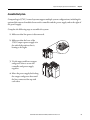
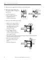
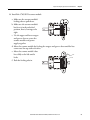
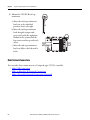
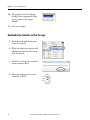
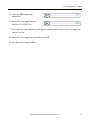
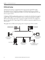
1
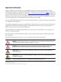
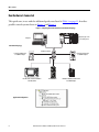
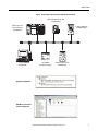
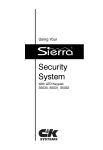
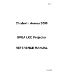
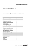
Quick Start
CompactLogix 5370 L3 Controllers
Catalog Numbers 1769-L30ER, 1769-L30ERM, 1769-L30ER-NSE, 1769-L33ER, 1769-L33ERM, 1769-L36ERM
Important User Information
Solid-state equipment has operational characteristics differing from those of electromechanical equipment. Safety
Guidelines for the Application, Installation and Maintenance of Solid State Controls (publication SGI-1.1 available from
your local Rockwell Automation sales office or online at http://www.rockwellautomation.com/literature/) describes some
important differences between solid-state equipment and hard-wired electromechanical devices. Because of this difference,
and also because of the wide variety of uses for solid-state equipment, all persons responsible for applying this equipment
must satisfy themselves that each intended application of this equipment is acceptable.
In no event will Rockwell Automation, Inc. be responsible or liable for indirect or consequential damages resulting from the
use or application of this equipment.
The examples and diagrams in this manual are included solely for illustrative purposes. Because of the many variables and
requirements associated with any particular installation, Rockwell Automation, Inc. cannot assume responsibility or
liability for actual use based on the examples and diagrams.
No patent liability is assumed by Rockwell Automation, Inc. with respect to use of information, circuits, equipment, or
software described in this manual.
Reproduction of the contents of this manual, in whole or in part, without written permission of Rockwell Automation,
Inc., is prohibited.
Throughout this manual, when necessary, we use notes to make you aware of safety considerations.
WARNING: Identifies information about practices or circumstances that can cause an explosion in a hazardous environment,
which may lead to personal injury or death, property damage, or economic loss.
ATTENTION: Identifies information about practices or circumstances that can lead to personal injury or death, property
damage, or economic loss. Attentions help you identify a hazard, avoid a hazard, and recognize the consequence.
SHOCK HAZARD: Labels may be on or inside the equipment, for example, a drive or motor, to alert people that dangerous
voltage may be present.
BURN HAZARD: Labels may be on or inside the equipment, for example, a drive or motor, to alert people that surfaces may
reach dangerous temperatures.
IMPORTANT
Identifies information that is critical for successful application and understanding of the product.
Allen-Bradley, CompactLogix, ControlFLASH, Kinetix, Logix5000, PanelView, POINT I/O, PowerFlex, Rockwell Software, Rockwell Automation, RSLinx, RSNetWorxStratix 6000, Studio 5000, and TechConnect are
trademarks of Rockwell Automation, Inc.
Trademarks not belonging to Rockwell Automation are property of their respective companies.
Where to Start
Follow the path that matches your hardware and network configuration.
Prepare the CompactLogix 5370 L3
Controller Hardware
Required
page 17
Required
Prepare the Computer and Load
Controller Firmware
page 33
Optional
POINT I/O™
Modules
PowerFlex® 40
Drive
PowerFlex 70
Drive
Kinetix® 350
Drive
PanelView™
Plus Terminal
PORT
MOD
NET B
NET A
STS
For more information on using each optional
device, see Table 1 on page 12.
Optional
Configure the EtherNet/IP
Network
Configure the DeviceNet
Network
page 49
page 53
Create a Logix
Designer Project
Required
page 63
Rockwell Automation Publication IASIMP-QS023B-EN-P - December 2012
3
Where to Start
How Hardware Is Connected
This quick start, in use with the additional quick starts listed in Table 1 on page 12, describes
possible control systems shown in Figure 1 and Figure 2.
Figure 1 - CompactLogix 5370 L3 Controller in a Star Network Topology
CompactLogix™ 5370
L3 Control System
Computer
1 (Front)
2 (Rear)
Star Network Topology
Stratix 6000 Switch
PORT
MOD
NET B
NET A
PowerFlex 40 Drive with
22-COMM-E Adapter
8 7
6 5
STS
PowerFlex 70 Drive with
20-COMM-E Adapter
4 3
2 1
PanelView Plus Terminal with Built-in
EtherNet/IP Port
Kinetix 350 Drive
Distributed POINT I/O Modules with
1734-AENT Adapter
Application Configuration
4
Rockwell Automation Publication IASIMP-QS023B-EN-P - December 2012
Where to Start
Figure 2 - CompactLogix 5370 L3 Controllers Using a DeviceNet Network
Distributed POINT I/O Modules with
1734-ADN Adapter
CompactLogix 5370 L3
Control System with
1769-SDN Module
PowerFlex 70 Drive with
20-COMM-D Adapter
1 (Front)
2 (Rear)
Computer with
1784-U2DN Cable
1606-XLDNET4
DeviceNet Power Supply
PowerFlex 40 Drive with 22COMM-D Adapter
Application Configuration
RSNetWorx™ for DeviceNet
Software Configuration
Rockwell Automation Publication IASIMP-QS023B-EN-P - December 2012
5
Where to Start
Sample Panel Layout
The sample panel layout shows the orientation of an example CompactLogix 5370 L3 control
system using EtherNet/IP networks and DeviceNet networks.
IMPORTANT
The specific layout of CompactLogix 5370 L3 control systems varies by application. The following graphic is an example
panel layout. The graphic shows a PowerFlex 40 drive used on a DeviceNet network. You can also use a PowerFlex 40
drive on an EtherNet/IP network.
PanelView Plus Terminal
AC Line Filter
Through-the-door
Disconnect
Line Interface
Module
E-Stop Push Button
PowerFlex 70 Drive
Kinetix 350 Drive
1 (Front)
2 (Rear)
CompactLogix 5370 L3
Control System
Ethernet
Switch
Distributed POINT I/O
Modules
DeviceNet KwikLink System
DeviceNet Power Supply
PowerFlex 40 Drive
6
Rockwell Automation Publication IASIMP-QS023B-EN-P - December 2012
Table of Contents
Preface
About the CompactLogix L3 Controllers . . . . . . . . . . . . . . . . . . . . . . . . . .
Choose to Integrate Optional Devices . . . . . . . . . . . . . . . . . . . . . . . . . . . . .
Studio 5000 Environment . . . . . . . . . . . . . . . . . . . . . . . . . . . . . . . . . . . . . . . .
Required Software . . . . . . . . . . . . . . . . . . . . . . . . . . . . . . . . . . . . . . . . . . . . . . .
Parts List . . . . . . . . . . . . . . . . . . . . . . . . . . . . . . . . . . . . . . . . . . . . . . . . . . . . . . . .
Additional Resources . . . . . . . . . . . . . . . . . . . . . . . . . . . . . . . . . . . . . . . . . . . . .
10
12
13
14
15
16
Chapter 1
Prepare the CompactLogix 5370 L3
Controller Hardware
Before You Begin . . . . . . . . . . . . . . . . . . . . . . . . . . . . . . . . . . . . . . . . . . . . . . . .
What You Need . . . . . . . . . . . . . . . . . . . . . . . . . . . . . . . . . . . . . . . . . . . . . . . . .
Follow These Steps . . . . . . . . . . . . . . . . . . . . . . . . . . . . . . . . . . . . . . . . . . . . . . .
Install the Networks. . . . . . . . . . . . . . . . . . . . . . . . . . . . . . . . . . . . . . . . . . . . . .
Install the Secure Digital Card . . . . . . . . . . . . . . . . . . . . . . . . . . . . . . . . . . . .
Assemble the System . . . . . . . . . . . . . . . . . . . . . . . . . . . . . . . . . . . . . . . . . . . . .
Make Network Connections . . . . . . . . . . . . . . . . . . . . . . . . . . . . . . . . . . . . . .
Make USB Connection . . . . . . . . . . . . . . . . . . . . . . . . . . . . . . . . . . . . . . .
Make an EtherNet/IP Network Connection. . . . . . . . . . . . . . . . . . . .
Make a DeviceNet Network Connection (Optional) . . . . . . . . . . . .
Wire Power. . . . . . . . . . . . . . . . . . . . . . . . . . . . . . . . . . . . . . . . . . . . . . . . . . . . . .
17
18
19
20
21
23
26
27
28
29
32
Chapter 2
Prepare the Computer and Load
Controller Firmware
Before You Begin . . . . . . . . . . . . . . . . . . . . . . . . . . . . . . . . . . . . . . . . . . . . . . . .
What You Need . . . . . . . . . . . . . . . . . . . . . . . . . . . . . . . . . . . . . . . . . . . . . . . . .
Follow These Steps . . . . . . . . . . . . . . . . . . . . . . . . . . . . . . . . . . . . . . . . . . . . . . .
Install the Studio 5000 Environment . . . . . . . . . . . . . . . . . . . . . . . . . . . . . .
Automatic Installation of ControlFLASH Software. . . . . . . . . . . . . . . . .
Configure an EtherNet/IP Driver in RSLinx Classic Software . . . . . . .
Set the IP Address for the Computer. . . . . . . . . . . . . . . . . . . . . . . . . . . . . . .
Load the Controller Firmware . . . . . . . . . . . . . . . . . . . . . . . . . . . . . . . . . . . .
Install Additional Software . . . . . . . . . . . . . . . . . . . . . . . . . . . . . . . . . . . . . . .
33
34
35
36
38
38
41
44
48
Chapter 3
Configure the EtherNet/IP Network
Before You Begin . . . . . . . . . . . . . . . . . . . . . . . . . . . . . . . . . . . . . . . . . . . . . . . . 50
What You Need . . . . . . . . . . . . . . . . . . . . . . . . . . . . . . . . . . . . . . . . . . . . . . . . . 51
Assign an IP Address to the Controller Over a USB Connection . . . . . 51
Rockwell Automation Publication IASIMP-QS023B-EN-P - December 2012
7
Table of Contents
Chapter 4
Configure the DeviceNet Network
Before You Begin. . . . . . . . . . . . . . . . . . . . . . . . . . . . . . . . . . . . . . . . . . . . . . . . .
What You Need. . . . . . . . . . . . . . . . . . . . . . . . . . . . . . . . . . . . . . . . . . . . . . . . . .
Follow These Steps . . . . . . . . . . . . . . . . . . . . . . . . . . . . . . . . . . . . . . . . . . . . . . .
Apply Power to the DeviceNet Network . . . . . . . . . . . . . . . . . . . . . . . . . . .
Set the 1769-SDN Module’s Node Address. . . . . . . . . . . . . . . . . . . . . . . . .
Create a DeviceNet Configuration File. . . . . . . . . . . . . . . . . . . . . . . . . . . . .
53
54
55
56
57
59
Chapter 5
Create a Logix Designer Project
Before You Begin. . . . . . . . . . . . . . . . . . . . . . . . . . . . . . . . . . . . . . . . . . . . . . . . .
What You Need. . . . . . . . . . . . . . . . . . . . . . . . . . . . . . . . . . . . . . . . . . . . . . . . . .
Follow These Steps . . . . . . . . . . . . . . . . . . . . . . . . . . . . . . . . . . . . . . . . . . . . . . .
Create a Project . . . . . . . . . . . . . . . . . . . . . . . . . . . . . . . . . . . . . . . . . . . . . . . . . .
Configure the Controller . . . . . . . . . . . . . . . . . . . . . . . . . . . . . . . . . . . . . . . . .
Add Local I/O Module . . . . . . . . . . . . . . . . . . . . . . . . . . . . . . . . . . . . . . . . . . .
Add the 1769-SDN to the Project . . . . . . . . . . . . . . . . . . . . . . . . . . . . . . . . .
Add Ladder Logic to Test the Local 1769-OB16 Module . . . . . . . . . . . .
Download to the Controller and Test the Logic. . . . . . . . . . . . . . . . . . . . .
64
64
65
66
68
70
71
73
76
Appendix A
Understanding Other
Application Options
DLR Network Topology . . . . . . . . . . . . . . . . . . . . . . . . . . . . . . . . . . . . . . . . . .
Follow These Steps . . . . . . . . . . . . . . . . . . . . . . . . . . . . . . . . . . . . . . . . . . .
Integrated Motion on the EtherNet/IP Network. . . . . . . . . . . . . . . . . . . .
Follow These Steps . . . . . . . . . . . . . . . . . . . . . . . . . . . . . . . . . . . . . . . . . . .
Index
. . . . . . . . . . . . . . . . . . . . . . . . . . . . . . . . . . . . . . . . . . . . . . . . . . . . . . . . . . . . . . . . . .83
8
Rockwell Automation Publication IASIMP-QS023B-EN-P - December 2012
80
81
82
82
Preface
This quick start describes how to use CompactLogix 5370 L3 controllers to install a simple
CompactLogix 5370 L3 control system and execute a task with a local 1769 Compact I/O
output module. The programming examples included are not complex, and offer solutions to
verify that devices are functioning and communicating properly.
IMPORTANT
Consider the following points:
• A typical CompactLogix 5370 L3 control system includes more components than listed in this quick start. For
example, you can use 1734 POINT I/O modules over an EtherNet/IP network in a CompactLogix 5370 L3 control
system. Other quick starts describe how to use additional components with your control system.
For a list of quick starts describing how to use other components in Logix5000™ control systems, see Choose to
Integrate Optional Devices on page 12.
• Not all tasks described in this quick start are required to complete the final task, that is, use ladder logic to test a
1769-OB16 output module as described beginning on page 73. For example, you do not need a DeviceNet
configuration file to test the module.
We expect that you might attempt to complete additional tasks with your control system by using the publications
listed on page 12. When you use those publications, some assumptions are made. For example, if you use a
PanelView Plus terminal over an EtherNet/IP network in a CompactLogix 5370 L3 control system, you must have
already created project and assigned an IP address to the controller.
If you complete all of the tasks described in this quick start, you can easily complete the tasks described in the
publications listed on page 12.
The following topics are described in this quick start:
•
Installing hardware for a basic CompactLogix 5370 L3 control system
•
Installing software required for the basic CompactLogix 5370 L3 control system
•
Installing and configuring an EtherNet/IP network and a DeviceNet network
•
Creating a software project
Rockwell Automation Publication IASIMP-QS023B-EN-P - December 2012
9
Preface
About the CompactLogix L3 Controllers
These CompactLogix 5370 L3 controllers are available:
• 1769-L30ER
• 1769-L30ERM
• 1769-L30ER-NSE
• 1769-L33ER
• 1769-L33ERM
• 1769-L36ERM
IMPORTANT
The tasks described in this publication use a 1769-L36ERM controller.
These features are available on CompactLogix 5370 L3 controllers.
10
•
Secure digital (SD) card for nonvolatile memory storage
•
Network connections:
– USB (single port)
– EtherNet/IP network - Option to use the controller in device-level ring (DLR), linear,
and star topologies on EtherNet/IP networks
– DeviceNet network - Via a 1769-SDN scanner module
Rockwell Automation Publication IASIMP-QS023B-EN-P - December 2012
Preface
•
I/O module options:
– 1769 Compact I/O modules as local expansion module
– Control of distributed I/O modules over a DeviceNet or EtherNet/IP network
•
Support for Integrated Motion on the EtherNet/IP network with the 1769-L30ERM,
1769-L33ERM, 1769-L36ERM controllers only.
For more information on using the 1769-L30ERM, 1769-L33ERM, 1769-L36ERM
controller in an application that includes Integrated Motion on the EtherNet/IP network,
see Appendix A, Understanding Other Application Options on page 79.
This graphic shows an example CompactLogix 5370 L3 control system.
Rockwell Automation Publication IASIMP-QS023B-EN-P - December 2012
11
Preface
Choose to Integrate Optional Devices
You can integrate multiple optional devices into a CompactLogix 5370 L3 control system. You
can use these devices on DeviceNet or EtherNet/IP networks.
This table describes optional devices you might use in a CompactLogix 5370 L3 control
controller system and what resources to use for each.
Table 1 - Devices in Logix5000 Control System
Device Type
Product Line(1)
Additional Resource with More Information
Distributed I/O
POINT I/O
Logix5000 Control Systems: Connect POINT I/O Modules over a DeviceNet Network
Quick Start, publication IASIMP-QS026
Logix5000 Control Systems: Connect POINT I/O Modules over an EtherNet/IP Network
Quick Start, publication IASIMP-QS027
Drives
PowerFlex40
Logix5000 Control Systems: Connect PowerFlex 40 Drives over a DeviceNet Network
Quick Start, publication IASIMP-QS028
Logix5000 Control Systems: Connect PowerFlex 40 Drives over an EtherNet/IP
Network Quick Start, publication IASIMP-QS029
PowerFlex 70
PORT
MOD
NET B
NET A
STS
HMI terminals
Logix5000 Control Systems: Connect PowerFlex 70 Drives over a DeviceNet Network
Quick Start, publication IASIMP-QS030
Logix5000 Control Systems: Connect PowerFlex 70 Drives over an EtherNet/IP
Network Quick Start, publication IASIMP-QS031
Kinetix 350
Logix5000 Control Systems: Connect Kinetix 350 Drives over an EtherNet/IP Network
Quick Start, publication IASIMP-QS032
PanelView Plus
Logix5000 Control Systems: Connect PanelView Plus Terminals over an EtherNet/IP
Network Quick Start, publication IASIMP-QS033
(1) You can use other I/O modules, drives, and HMI terminals in Logix5000 control systems. These product lines are used for example purposes.
12
Rockwell Automation Publication IASIMP-QS023B-EN-P - December 2012
Preface
Studio 5000 Environment
The Studio 5000™ Engineering and Design Environment combines engineering and design
elements into a common environment. The first element in the Studio 5000 environment is the
Logix Designer application. The Logix Designer application is the rebranding of RSLogix™ 5000
software and will continue to be the product to program Logix5000™ controllers for discrete,
process, batch, motion, safety, and drive-based solutions.
The Studio 5000 environment is the foundation for the future of Rockwell Automation
engineering design tools and capabilities. It is the one place for design engineers to develop all of
the elements of their control system.
Rockwell Automation Publication IASIMP-QS023B-EN-P - December 2012
13
Preface
Required Software
Before attempting to complete any of the tasks described in this publication, verify that your
computer meets the following operating system and service pack compatibility requirements:
• Microsoft Windows 7 Professional (64-bit) with Service Pack 1
• Microsoft Windows 7 Home Premium (64-bit) with Service Pack 1
• Microsoft Windows 7 Home Premium (32-bit) with Service Pack 1
• Microsoft Windows Server 2008 R2 Standard Edition with Service Pack 1
If your computer does not meet the operating system and service pack compatibility
requirements, perform the necessary upgrades before continuing.
Table 2 lists the software used in this quick start. Specific software requirements are listed at the
beginning of each chapter.
Table 2 - Software Used in This Quick Start
Software
Minimum Version
Required
Studio 5000
21.00.00
Yes
Logix Designer application
21.00.00
Yes
RSLinx® Classic
3.51.00
Yes
ControlFLASH™
12.00.00 - Automatically installed with Studio 5000
installation
Yes
RSNetWorx for DeviceNet
21.00.00
No(1)
(1) Installing RSNetworx for DeviceNet is only required if the automation system includes a DeviceNet network. We recommend that you install RSNetWorx for DeviceNet software to use with devices on a
DeviceNet network as described in publications listed in Table 1. For more information, see Chapter 4, Configure the DeviceNet Network on page 53.
14
Rockwell Automation Publication IASIMP-QS023B-EN-P - December 2012
Preface
Parts List
Table 3 lists the hardware used in this quick start.
For example, if you do not intend to use a DeviceNet network to complete tasks described in
some publications listed in Table 1, you do not need the hardware related to installing a
DeviceNet network.
Specific hardware requirements are listed at the beginning of each chapter.
Table 3 - Parts Used with This Quick Start
Quantity
Cat. No.
Description
2 or 3
N/A
DIN rail (steel, not aluminum)
1
One of the following:
CompactLogix 5370 L3 controllers
The tasks described in this publication use a 1769-L36ERM controller.
•
•
•
•
•
•
1769-L30ER
1769-L30ERM
1769-L30ER-NSE
1769-L33ER
1769-L33ERM
1769-L36ERM
1
1769-PA4
Compact I/O power supply
1
1769-OB16
Compact 16-point 24V DC sourcing output module
1
1769-ECR
Compact I/O right end cap/terminator
1
1783-EMS08T
Stratix™ 6000 Ethernet managed switche
1
External power supply for Stratix 6000 Ethernet managed switch
1
1585J-M8PBJM-2
RJ45-to-RJ45 patchcord Ethernet cables
1
1769-SDN
Compact I/O DeviceNet scanner
1
1485C-P1E75
KwikLink™ flat cable, 75 m (246 ft)
2
1485A-T1E4
KwikLink terminator/resistor
1
1485P-P1E4-R5
KwikLink sealed micro connector
1
1485K-P1F5-C
KwikLink QD cordset micro right-angle male
1
1606-XLDNET8
DeviceNet power supply
1
1485T-P1E4-B1
KwikLink power tap module
Rockwell Automation Publication IASIMP-QS023B-EN-P - December 2012
15
Preface
Additional Resources
These documents contain additional information concerning related products from
Rockwell Automation.
Resource
Description
CompactLogix 5370 Controllers User Manual,
publication 1769-UM021
Describes how to design, install, operate, and troubleshoot a CompactLogix 5370
control system.
Logix5000 Control Systems: Connect POINT I/O
Modules over a DeviceNet Network Quick Start,
publication IASIMP-QS026
Describes basic steps required to include distributed POINT I/O modules over a
DeviceNet network in a Logix5000 control system, including hardware, firmware,
and software considerations.
Logix5000 Control Systems: Connect POINT I/O
Modules over an EtherNet/IP Network Quick Start,
publication IASIMP-QS027
Describes basic steps required to include distributed POINT I/O modules over an
EtherNet/IP network in a Logix5000 control system, including hardware, firmware,
and software considerations.
Logix5000 Control Systems: Connect a PowerFlex
40 Drive over a DeviceNet Network Quick Start,
publication IASIMP-QS028
Describes basic steps required to include PowerFlex 40 drives over a DeviceNet
network in a Logix5000 control system, including hardware, firmware, and
software considerations.
Logix5000 Control Systems: Connect a PowerFlex
40 Drive over a EtherNet/IP Network Quick Start,
publication IASIMP-QS029
Describes basic steps required to include PowerFlex 40 drives over an EtherNet/IP
network in a Logix5000 control system, including hardware, firmware, and
software considerations.
Logix5000 Control Systems: Connect a PowerFlex
70 Drive over a DeviceNet Network Quick Start,
publication IASIMP-QS030
Describes basic steps required to include PowerFlex 70 drives over a DeviceNet
network in a Logix5000 control system, including hardware, firmware, and
software considerations.
Logix5000 Control Systems: Connect a PowerFlex
70 Drive over an EtherNet/IP Network Quick Start,
publication IASIMP-QS031
Describes basic steps required to include PowerFlex 70 drives over an EtherNet/IP
network in a Logix5000 control system, including hardware, firmware, and
software considerations.
Logix5000 Control Systems: Connect a Kinetix 350
Multi-axis Servo Drive System over an EtherNet/IP
Network Quick Start, publication IASIMP-QS032
Describes basic steps required to include Kinetix 350 Multi-axis Servo drives over
an EtherNet/IP network in a Logix5000 control system, including hardware,
firmware, and software considerations.
Logix5000 Control Systems: Connect a PanelView
Plus Terminal over an EtherNet/IP Network Quick
Start, publication IASIMP-QS033
Describes basic steps required to include PanelView Plus terminals over an
EtherNet/IP network in a Logix5000 control system, including hardware, firmware,
and software considerations.
ControlFLASH Firmware Upgrade Kit, publication
1756-QS105
Provides details regarding the installation of ControlFlash software and execution
of firmware upgrades.
Industrial Automation Wiring and Grounding
Guidelines, publication 1770-4.1
Provides general guidelines for installing a Rockwell Automation industrial
system.
Product Certifications website, http://www.ab.com Provides declarations of conformity, certificates, and other certification details.
You can view or download publications at http://www.rockwellautomation.com/literature/. To
order paper copies of technical documentation, contact your local Allen-Bradley distributor or
Rockwell Automation sales representative.
16
Rockwell Automation Publication IASIMP-QS023B-EN-P - December 2012
Chapter
1
Prepare the CompactLogix 5370 L3 Controller Hardware
This chapter describes how to install the hardware needed for your CompactLogix 5370 L3
control system.
Before You Begin
Determine which network or networks your control system uses. You can use
CompactLogix 5370 L3 controllers on an EtherNet/IP network and on a DeviceNet network.
Rockwell Automation Publication IASIMP-QS023B-EN-P - December 2012
17
Chapter 1
Prepare the CompactLogix 5370 L3 Controller Hardware
What You Need
Table 4 lists the hardware components used in this chapter. The parts listed in this table are done
so with the assumption that you will install an EtherNet/IP and DeviceNet network.
Table 4 - Parts Used with This Quick Start
Quantity
Cat. No.
Description
1 or more
N/A
DIN rail (steel, not aluminum)
1
One of the following:
• 1769-L30ER
• 1769-L30ERM
• 1769-L30ER-NSE
• 1769-L33ER
• 1769-L33ERM
• 1769-L36ERM
CompactLogix 5370 L3 controller
The tasks described in this publication use a
1769-L36ERM controller.
1
1769-PA4
Bus power supply
1
1606-XLDNET8
DeviceNet network power supply
1
1769-ECR
Compact I/O end cap/terminator
1 or more
1585J-M4TBJM-2
Ethernet cable (straight-through)
1
1783-EMS08T
Stratix 6000 Ethernet managed switch
1
External power supply for Stratix 6000 Ethernet
managed switch
1
1769-SDN
DeviceNet communication module
1
1769-OB16
Compact I/O output module
1
1485C-P1E75
KwikLink flat cable, 75 m (246 ft)
2
1485A-T1E4
KwikLink terminator/resistor
2 or more
1485P-P1E4-R5
KwikLink sealed micro connector
1 or more
1485K-P1F5-C
KwikLink QD Cordset Micro right-angle male
1
1485T-P1E4-B1
KwikLink power tap module
18
Rockwell Automation Publication IASIMP-QS023B-EN-P - December 2012
Prepare the CompactLogix 5370 L3 Controller Hardware
Follow These Steps
Install the
Networks
page 20
Install the Secure
Digital Card
page 21
Assemble the
System
page 23
Make Network
Connections
page 26
Wire Power
page 32
Rockwell Automation Publication IASIMP-QS023B-EN-P - December 2012
Chapter 1
1 (Front)
2 (Rear)
19
Chapter 1
Prepare the CompactLogix 5370 L3 Controller Hardware
Install the Networks
Before you install your CompactLogix 5370 L3 control hardware, you must install the network
on which it will operate, that is, an EtherNet/IP or DeviceNet network.
We recommend that you install both networks.
For more information on installing either of these networks, see the publications listed in the
following table.
Network
Publication Title
Publication Number
EtherNet/IP
EtherNet/IP Media Planning and Installation Manual
NA - Click here to access the publication
Stratix 6000 Ethernet Managed Switches Installation Instructions
1783-IN004
Stratix 6000 Ethernet Managed Switch User Manual
1783-UM001
DeviceNet Media Design and Installation Guide
DNET-UM072
DeviceNet
The publications listed previously describe how to install the communication network and not
how to connect your controller to the network. Make Network Connections on page 26
describes how to connect your controller to the networks.
20
Rockwell Automation Publication IASIMP-QS023B-EN-P - December 2012
Prepare the CompactLogix 5370 L3 Controller Hardware
Chapter 1
Install the Secure Digital Card
The secure digital (SD) card provides nonvolatile storage for the CompactLogix 5370 L3
controller. You can store projects to an SD card or load a project from an SD card.
There following SD cards are available with for use with your CompactLogix 5370 L3 controller.
• 1784-SD1 card - 1 Gb of memory
• 1784-SD2 card - 2 Gb of memory
The CompactLogix 5370 L3 controllers ship from the factory with the 1784-SD1 SD card
installed.
Complete these steps to re-install an SD card that has been removed from the controller back
into the controller or if installing a new SD card into the controller.
WARNING: When you insert or remove the Secure Digital (SD) Card while power is on, an electrical arc can occur. This
could cause an explosion in hazardous location installations.
Be sure that power is removed or the area is nonhazardous before proceeding.
1. Verify that the SD card is locked or
unlocked according to your
preference. Consider these points
whe deciding to lock the card
before installation.
•
•
Unlocked
Locked
If the card is unlocked, the controller can write data to it or read data from it.
If the card is locked, the controller can only read data from it.
2. Open the door for the SD card.
Rockwell Automation Publication IASIMP-QS023B-EN-P - December 2012
21
Chapter 1
Prepare the CompactLogix 5370 L3 Controller Hardware
3. Insert the SD card into the SD
card slot.
You can install the SD card in one
orientation only. The beveled
corner should be at the top. An
orientation logo is printed on the
card.
If you feel resistance when
inserting the SD card, pull it out and change the orientation.
4. Gently press the card until it clicks
into place.
5. Close the SD card door.
22
Rockwell Automation Publication IASIMP-QS023B-EN-P - December 2012
Prepare the CompactLogix 5370 L3 Controller Hardware
Chapter 1
Assemble the System
CompactLogix 5370 L3 control systems support multiple system configurations, including the
optional placement of modules between the controller and the power supply and to the right of
the power supply.
Complete the following steps to assemble the system.
1. Make sure that line power is disconnected.
2. Make sure that the lever of the
1769 Compact power supply is in
the unlocked position, that is,
leaning to the right.
t)
on
1 (Fr ar)
2 (Re
3. Use the upper and lower tongueand-groove slots to secure the
controller and power supply
together.
4. Move the power supply back along
the tongue-and-groove slots until
the bus connectors line up with
each other.
Rockwell Automation Publication IASIMP-QS023B-EN-P - December 2012
23
Chapter 1
Prepare the CompactLogix 5370 L3 Controller Hardware
5. Move the power supply’s bus level fully to the left until it locks.
6. Mount the CompactLogix 5370
L3 controller and power supply on
the DIN rail.
a. Pull locking tabs out
b. Slide controller and power
supply into position.
c. Push the locking tabs in.
7. Mount the 1769-OB16 output module.
a. Make sure the output module’s
locking tabs are pulled out and
the module’s bus lever is in the
unlocked position, that is,
leaning to the right..
b. Use the upper and lower
tongue-and-groove slots to
secure the output module and
power supply together.
c. Move the output module back along the tongue-and-groove slots until the bus
connectors line up with each other.
d. Move the output module’s bus
lever fully to the left until it
locks.
e. Push the locking tabs in.
24
Rockwell Automation Publication IASIMP-QS023B-EN-P - December 2012
Prepare the CompactLogix 5370 L3 Controller Hardware
Chapter 1
8. Install the 1769-SDN scanner module.
a. Make sure the scanner module’s
locking tabs are pulled out.
b. Make sure the scanner module’s
bus lever is in the unlocked
position, that is, leaning to the
right.
c. Use the upper and lower tongueand-groove slots to secure the
scanner module and power
supply together.
d. Move the scanner module back along the tongue-and-groove slots until the bus
connectors line up with each other.
e. Move the scanner module’s bus
lever fully to the left until it
locks.
f. Push the locking tabs in.
Rockwell Automation Publication IASIMP-QS023B-EN-P - December 2012
25
Chapter 1
Prepare the CompactLogix 5370 L3 Controller Hardware
9. Mount the 1769-ECR end cap
terminator.
a. Move the end cap terminator’s
bus lever to the unlocked
position, that is, the right.
b. Move the end cap terminator
back along the tongue-andgroove slots with the rightmost
module in the system until the
bus connectors line up with each
other.
c. Move the end cap terminator’s
bus lever fully to the left until it
locks.
Make Network Connections
You can make these connections to a CompactLogix 5370 L3 controller:
• Make USB Connection
• Make an EtherNet/IP Network Connection
• Make a DeviceNet Network Connection (Optional)
26
Rockwell Automation Publication IASIMP-QS023B-EN-P - December 2012
Prepare the CompactLogix 5370 L3 Controller Hardware
Chapter 1
Make USB Connection
IMPORTANT
You must use RSLinx Classic software, version 2.59.xx or later, with your CompactLogix 5370 L3 controllers. With this
software version, there is no need to install an RSLinx Classic software driver. The driver appears automatically in the
software when a USB cable is connected to the controller and the computer.
The controller has a USB port that uses a Type B receptacle. The port is USB 2.0-compatible and
operates at 12 Mbps.
Use a USB cable to connect your computer to the USB port. With this connection, you can
upgrade firmware and download programs to the controller directly from your computer.
ATTENTION: The USB port is intended for temporary local programming purposes only and not intended for
permanent connection.
The USB cable is not to exceed 3.0 m (9.84 ft) and must not contain hubs.
WARNING: Do not use the USB port in hazardous locations.
1. Plug the USB cable into your CompactLogix 5370 L3 controller.
2. Plug the USB cable into your
computer.
32152-M
Rockwell Automation Publication IASIMP-QS023B-EN-P - December 2012
27
Chapter 1
Prepare the CompactLogix 5370 L3 Controller Hardware
Make an EtherNet/IP Network Connection
IMPORTANT
This section assumes that you installed a 1783-EMS08T Stratix 6000 Ethernet managed switch on the DIN rail when you
installed your EtherNet/IP network as described on Install the Networks on page 20.
1. Plug a 1585J-M4TBJM-1,
Ethernet cable (straight-through)
into a port on the Stratix 6000.
2. Plug the other end of the Ethernet
cable into one of the Ethernet
ports on the bottom of the
controller.
8 7
6 5
4 3
2 1
Set Network IP Address
Once you connect the CompactLogix 5370 L3 controller to an EtherNet/IP network, you must
assign the controller a unique IP address.
For information about how to set the network IP address for your controller, see Chapter 3,
Configure the EtherNet/IP Network on page 49.
28
Rockwell Automation Publication IASIMP-QS023B-EN-P - December 2012
Prepare the CompactLogix 5370 L3 Controller Hardware
Chapter 1
Make a DeviceNet Network Connection (Optional)
1. Attach and lock the
1606-XLDNET8 DeviceNet
power supply to the DIN rail.
1606-X
POWE
AC 120
The power supply uses a locking
tab at the top that you push down
to secure it to the DIN rail.
2. Assemble the DeviceNet network
cable system using the KwikLink
flat cable, terminators, and sealed
micro connectors for each device.
See instructions included
with devices.
AC 240
R SUP
L
PLY
V
V
Input
AC 100
-120/2
N L
00-240
Outp
V
Isolate
power
before
disconn
ecting
DC ok
200W ut
Lim
DC 24V ited Pow
er
/ 8A
+ –
DC ok
KwikLink Sealed
Terminator
KwikLink Sealed
Micro Connector
3. Wire a KwikLink QD Micro
Cordset to the 1769-SDN
connector.
Connect
Red
White
Bare
Blue
Black
To
V+
CAN High
Shield
CAN Low
V-
KwikLink Sealed
Terminator
To other device on
network
To other device on
network
1606-XLDNET8
DeviceNet Power Supply
1606-X
POWE
L
R SUPPL
Y
AC 120
V
AC 240
V
Input
AC 100
-120/2
N L
00-240
Outp
V
Isolate
power
before
disconn
ecting
DC ok
200W ut
Lim
DC 24V ited Powe
r
/ 8A
+ –
DC ok
Rockwell Automation Publication IASIMP-QS023B-EN-P - December 2012
29
Chapter 1
Prepare the CompactLogix 5370 L3 Controller Hardware
4. Connect the 1769-SDN module’s
grounding screw to the panel.
Grounding Screw
Use 2.08 mm2 (14 AWG) wire to
connect to panel ground.
5. Connect the QD Micro Cordset
to a KwikLink sealed
microconnector on the network.
6. Wire the 1606-XLDNET8 DeviceNet power supply.
WARNING: Verify that all incoming power is turned off before wiring power.
a. Connect incoming power to the power supply.
Connect
To
V AC COM
N (neutral)
120/240V AC
L (line)
Ground
b. Place the switch in the position that matches your supply voltage.
30
Rockwell Automation Publication IASIMP-QS023B-EN-P - December 2012
Prepare the CompactLogix 5370 L3 Controller Hardware
Chapter 1
c. Connect the DeviceNet power tap to the power supply.
Connect
To
Red
+
White
N/A
Shield
N/A
Blue
N/A
Black
–
For this example, there is no need to connect the DC ok relay on the power supply to
anything.
ATTENTION: If you have unused DeviceNet wires, make sure they do not come into contact with the other wires.
7. Connect the DeviceNet power tap to the DeviceNet network.
8. Do not turn on incoming power.
Rockwell Automation Publication IASIMP-QS023B-EN-P - December 2012
31
Chapter 1
Prepare the CompactLogix 5370 L3 Controller Hardware
Wire Power
1769-PA4 Power Supply
WARNING: Verify that all incoming power is turned off before wiring power.
1. Set the V AC line input power switch behind the clear door to match your 120V or 240V
AC power source as directed by the DANGER label on the power supply.
The switch is shipped from the factory in the 240V AC position. Remove the switch label
that covers the connectors after setting the proper power switch.
2. Connect the ground screw of the power supply to the nearest ground or ground bus.
Use a 2.5 mm2 (14 AWG) wire and keep the leads as short as possible.
3. Wire the power supply according
to the graphics shown here.
TIP
This
symbol denotes a
protective earth ground terminal that
provides a low impedance path
between electrical circuits and earth
for safety purposes and provides
noise immunity improvement. This
connection must be made for safety
purposes.
4. Turn on incoming power.
Terminal Wiring Diagram
NOT USED
NOT USED
120/240V AC (L1)
V AC COM (L2)
CHASSIS GROUND
32
Rockwell Automation Publication IASIMP-QS023B-EN-P - December 2012
Chapter
2
Prepare the Computer and Load Controller Firmware
In this chapter, you install and configure the necessary programming and configuration software
on your computer and load firmware on your controller.
Before You Begin
Before you begin, complete these tasks:
•
Verify that your computer meets the software’s system requirements for installation and use
of the software listed in Table 5.
•
The tasks described in Chapter 1, Prepare the CompactLogix 5370 L3 Controller
Hardware on page 17, including the following:
–
–
–
–
Install the EtherNet/IP and/or the DeviceNet network.
Assemble the system.
Make network connections.
Wire power to the controller.
Rockwell Automation Publication IASIMP-QS023B-EN-P - December 2012
33
Chapter 2
Prepare the Computer and Load Controller Firmware
What You Need
Table 5 lists the components you use in this chapter.
Table 5 - What You Need to Prepare the Computer
Component
Description
Studio 5000 environment
Environment that combines engineering and design elements into a common environment.
Logix Designer application
Application used to create a project the CompactLogix 5370 L3 controller uses in your application.
RSLinx Classic software
Communication server that supports multiple software applications simultaneously, establishing
communicating between devices on many different Rockwell Automation Industrial networks.
IP address
A number in the form xxx.xxx.xxx.xxx where each xxx is a number from 000…254.
The IP address uniquely identifies the computer on the EtherNet/IP network.
Subnet mask
Extension of the IP address that allows a site to use a single network ID for multiple
physical networks.
If you change the subnet mask of an already-configured controller, you must cycle power to the
controller for the change to take effect.
ControlFLASH tool
Utility used to upgrade the firmware on certain Rockwell Automation products in a
CompactLogix 5370 L3 controller application.
Automatically installed with Studio 5000 environment installation.
RSNetWorx for DeviceNet software
34
Configuration software that creates a scanlist of devices that exchange information with the
controller over a DeviceNet network.
Rockwell Automation Publication IASIMP-QS023B-EN-P - December 2012
Prepare the Computer and Load Controller Firmware
Chapter 2
Follow These Steps
Install the Studio 5000
Environment
page 36
Configure an EtherNet/IP
Driver in RSLinx Classic
Software
page 38
Set the IP Address for
the Computer
page 41
Load the Controller
Firmware
page 44
Optional
Install Additional
Software
page 48
Rockwell Automation Publication IASIMP-QS023B-EN-P - December 2012
35
Chapter 2
Prepare the Computer and Load Controller Firmware
Install the Studio 5000 Environment
The Studio 5000 environment, version 21.00.00, installation process is configured so that,
among other software applications, RSLinx Classic software, version 3.51.00 and RSNetWorx
for DeviceNet software, version 21.00.00, are automatically installed.
The automatic installation option is enabled by default. You can change the installation settings
and install RSLinx Classic software or RSNetWorx for DeviceNet software separately. We
strongly recommend that you use the installation process default settings described in
this chapter.
IMPORTANT
The steps described in this section might vary slightly from the steps you complete during your Studio 5000
environment, version 21.00.00, installation.
1. Start the installation.
You can load the software from a CD or web download.
2. Choose a language, fill in the
appropriate information, and
click Next.
36
Rockwell Automation Publication IASIMP-QS023B-EN-P - December 2012
Prepare the Computer and Load Controller Firmware
Chapter 2
3. Use the default selections and
click Install.
4. Read the license agreement
carefully.
5. Click Accept All.
The installation process begins.
When installation is complete, your
computer will have the software
necessary required to complete the tasks
described in this publication.
Among other software, your computer
will have the following:
• Studio 5000 Environment, version 21.00.00
•
•
The Studio 5000 Environment, version 21.00.00 includes Logix Designer application,
version 21.00.00.
RSLinx Classic software, version 3.51.00
RSNetWorx for DeviceNet, version 21.00.00
You are prompted to activate the software. For more information on software activation, see
the following:
•
FactoryTalk Activations Frequently Asked Questions, publication FTALK-FA017.
Rockwell Automation Publication IASIMP-QS023B-EN-P - December 2012
37
Chapter 2
•
Prepare the Computer and Load Controller Firmware
Rockwell Automation Technical Support Software Activations site http://
www.rockwellautomation.com/support/activations.html
Automatic Installation of ControlFLASH Software
ControlFLASH software is used to upgrade a CompactLogix 5370 L3 controller’s firmware
revision. ControlFLASH software is automatically installed when you install the Studio 5000
environment.
For more information on loading firmware on your controller, see Load the Controller
Firmware on page 44.
Configure an EtherNet/IP Driver in RSLinx Classic Software
1. Start the software.
38
Rockwell Automation Publication IASIMP-QS023B-EN-P - December 2012
Prepare the Computer and Load Controller Firmware
Chapter 2
2. From the Communications pulldown menu, choose Configure
Drivers.
The Configure Drivers dialog box
appears.
3. From the Available Driver Types
pull-down menu, choose
EtherNet/IP Driver or Ethernet
devices and click Add New.
We recommend that you use
EtherNet/IP Driver.
The Add New RSLinx Driver
dialog box appears.
4. Click OK to keep the default
name.
A Configure driver:AB_ETHxxx
dialog box appears. The full name
of the dialog box varies by what
driver type was chosen in step 3.
This example uses the EtherNet/IP Driver; the driver name is AB_ETHIP-1.
Rockwell Automation Publication IASIMP-QS023B-EN-P - December 2012
39
Chapter 2
Prepare the Computer and Load Controller Firmware
5. Select an Ethernet card and
click OK.
This new driver is available.
6. Verify that the driver’s Status is
Running and click Close.
40
Rockwell Automation Publication IASIMP-QS023B-EN-P - December 2012
Prepare the Computer and Load Controller Firmware
Chapter 2
Set the IP Address for the Computer
Your computer requires an Internet Protocol (IP) address to operate on an EtherNet/IP
network. The IP address uniquely identifies the controller and is in the form xxx.xxx.xxx.xxx
where each xxx is a number from 000…254 with some exceptions for reserved values.
A computer’s IP address can be set automatically or manually. The manual option is typically
used with isolated networks. This section describes how to set the IP address manually.
For more information on setting an IP address for your CompactLogix 5370 L3 controller, see
the CompactLogix 5370 Controllers User Manual, publication 1769-UM021.
1. On your desktop, right-click
Network and choose Properties.
2. Click adapter settings.
Rockwell Automation Publication IASIMP-QS023B-EN-P - December 2012
41
Chapter 2
Prepare the Computer and Load Controller Firmware
3. Right-click Local Area
Connection and
choose Properties.
4. On the Networking tab, choose
Internet Protocol Version 4
(TCP/IPv4) and click Properties.
42
Rockwell Automation Publication IASIMP-QS023B-EN-P - December 2012
Prepare the Computer and Load Controller Firmware
Chapter 2
5. Select Use the following IP address
and enter an IP address and Subnet
mask for your computer.
6. Record the IP address and
subnet mask.
7. Click OK.
8. Close the Local Area Connection
Properties dialog box.
Rockwell Automation Publication IASIMP-QS023B-EN-P - December 2012
43
Chapter 2
Prepare the Computer and Load Controller Firmware
Load the Controller Firmware
IMPORTANT
This section assumes that you downloaded the controller firmware from the Rockwell Automation technical support
website to install on your CompactLogix 5370 L3 controller. If not, download the firmware before following the
steps in this section.
The firmware is available with Logix Designer application or you can download it from the support website.
Go to http://www.rockwellautomation.com/support/
This section describes how to load firmware on your CompactLogix 5370 L3 controller before setting an IP address
for the controller. In this case, you must connect from your workstation to the controller over the USB port.
With this quick start, you must use RSLinx Classic software, version 3.51.xx or later with CompactLogix 5370 L3
controllers. When the software is installed, a USB driver is automatically installed. When your computer is
connected to the CompactLogix 5370 L3 controller over a USB connection, the controller appears in the RSWho
window whenever you perform a Browse.
1. Verify that the SD card in the controller is unlocked.
2. Connect to the controller via the USB port as described in Make USB Connection on
page 27.
The controller should be powered. If it is not, turn power on to the controller.
3. Start the
ControlFLASH software.
44
Rockwell Automation Publication IASIMP-QS023B-EN-P - December 2012
Prepare the Computer and Load Controller Firmware
Chapter 2
4. Click Next.
5. Select the controller catalog
number and click Next.
Rockwell Automation Publication IASIMP-QS023B-EN-P - December 2012
45
Chapter 2
Prepare the Computer and Load Controller Firmware
6. Expand the USB driver, and
choose your controller.
7. Click OK.
8. Verify that your computer’s mode
switch is in the REM position.
RUN
REM
PROG
9. Choose the desired firmware
revision and click Next.
TIP
46
Consider the following:
• If the Current Revision
matches the firmware
revision shown in the box
below it, click Cancel. You are
finished with this task.
• This example uses firmware
revision 21.001.23. Your
firmware revision may be a
different number.
You can access the
latest firmware revision
at the Rockwell
Automation Technical
Support webpage.
Rockwell Automation Publication IASIMP-QS023B-EN-P - December 2012
Prepare the Computer and Load Controller Firmware
Chapter 2
10. To start the update of the
controller, click Finish and then
click Yes.
Before the firmware upgrade
begins, you see the following dialog
box. Take the appropriate action
for your application. In this
example, the upgrade continues
when OK is clicked.
After the controller is updated, the
status dialog box displays the
message Update complete.
11. Click OK.
12. To close the ControlFLASH utility, click Cancel and then click Yes.
Rockwell Automation Publication IASIMP-QS023B-EN-P - December 2012
47
Chapter 2
Prepare the Computer and Load Controller Firmware
Install Additional Software
Depending on your application, you may need to install additional software.
For example, if you are integrating a PanelView Plus terminal into your system, you must install
the following:
•
RSLinx Enterprise software
IMPORTANT
•
48
You must install this software before you install any other additional software.
FactoryTalkView Machine Edition software
Rockwell Automation Publication IASIMP-QS023B-EN-P - December 2012
Chapter
3
Configure the EtherNet/IP Network
In this chapter, you assign an IP address to your CompactLogix 5370 L3 controller.
This quick start does not describe how to use other devices on the EtherNet/IP network. It is
common, however, to use other devices on an EtherNet/IP network in a CompactLogix 5370 L1
control system. If you were to do so, for example, use a PanelView Plus terminal on an
EtherNet/IP network, you need to assign an IP address to those devices.
IMPORTANT
Not all tasks described in this quick start are required to complete the final task, that is, use ladder logic to test a
1769-OB16 output module as described beginning on page 73. For example, you do not need to install an
EtherNet/IP network to connect to a CompactLogix 5370 L3 controller because you can do so over a USB cable.
We expect that you might attempt to complete additional tasks with your control system by using the publications
listed on page 12 relating to using a component over an EtherNet/IP network in a Logix5000 control system. When you
use those publications, some assumptions are made. For example, if you use POINT I/O modules over an EtherNet/IP
network in a CompactLogix 5370 L3 control system, you must have already created a Logix Designer project and have an
IP address assigned to the controller.
If you complete all of the tasks described in this chapter, you can easily complete the tasks described in the publications
listed on page 12 related to using an EtherNet/IP network.
Rockwell Automation Publication IASIMP-QS023B-EN-P - December 2012
49
Chapter 3
Configure the EtherNet/IP Network
Before You Begin
Before you begin, complete these tasks.
•
The tasks described in Chapter 1, Prepare the CompactLogix 5370 L3 Controller
Hardware on page 17, including:
–
–
–
–
Install the EtherNet/IP network
Install the controller and the local expansion module 1769-OB16 output module
Wire power to the controller
Make network connections
IMPORTANT
•
The tasks described inChapter 2, Prepare the Computer and Load Controller Firmware on
page 33, including:
–
–
–
–
•
50
If you connect all of the devices, including the computer, through an Ethernet switch, you can create an
isolated network. This chapter assumes you are using an isolated network. If you are not, contact your
network administrator to obtain IP addresses.
Install the Studio 5000 environment and RSLinx Classic software
Logix Designer application is installed when you install the Studio 5000 environment.
Configure an EtherNet/IP driver in RSLinx Classic software
Set the IP address for the computer
Load firmware on the controller
Verify that power is applied to all devices
Rockwell Automation Publication IASIMP-QS023B-EN-P - December 2012
Configure the EtherNet/IP Network
Chapter 3
What You Need
Table 6 lists the software components you use in this chapter.
Table 6 - What You Need to Configure the EtherNet/IP Network
Component
Description
Studio 5000 environment
Environment that combines engineering and design elements into a common environment.
Logix Designer application
Application used to create a project the CompactLogix 5370 L3 controller uses in your application.
RSLinx Classic software
Communication server that supports multiple software applications simultaneously, establishing
communicating between devices on many different Rockwell Automation industrial networks.
IP address
A number in the form xxx.xxx.xxx.xxx where each xxx is a number from 000…254.
The IP address uniquely identifies the controller on the EtherNet/IP network.
Subnet mask
Extension of the IP address that allows a site to use a single network ID for multiple
physical networks.
If you change the subnet mask of a configured controller, you must cycle power to the controller
for the change to take effect.
Assign an IP Address to the Controller Over a USB Connection
At initial powerup, the CompactLogix 5370 L3 controller does not have an IP address. Use
RSLinx Classic software over a USB connection to assign an IP address. If the computer with
RSLinx Classic software is not connected to the controller via a USB connection, the following
steps will not work.
IMPORTANT
There are other methods to assign an IP address to the controller, such as using the BOOTP/DHCP utility. This section is
only one example of how to assign the IP address to the controller.
For more information on the methods of assign an IP address to the CompactLogix 5370 L3 controller, see the
CompactLogix 5370 Controllers User Manual, publication 1769-UM021.
1. Verify that your computer is connected to the USB port on the front of the controller.
Rockwell Automation Publication IASIMP-QS023B-EN-P - December 2012
51
Chapter 3
Configure the EtherNet/IP Network
2. From the Communications pulldown menu, choose RSWho.
The RSWho dialog box appears.
3. Navigate to the USB connection.
4. Right-click the controller and
choose Module Configuration.
The Module Configuration dialog
box appears.
5. Click the Port Configuration tab.
6. For Network Configuration Type,
click Static to permanently assign
this configuration to the port.
IMPORTANT
The controller’s default
configuration is Dynamic.
When the controller is
configured for Dynamic, on a
power cycle, it clears the
current IP address and resumes
sending BOOTP requests.
7. Enter the IP address and Network Mask for the controller.
8. Enter other network parameters, if necessary.
9. Click OK.
For more information on setting the network IP address, see EtherNet/IP Network
Configuration User Manual, publication ENET-UM001.
52
Rockwell Automation Publication IASIMP-QS023B-EN-P - December 2012
Chapter
4
Configure the DeviceNet Network
In this chapter, you configure the DeviceNet node address for the 1769-SDN module. You also
create the RSNetWorx for DeviceNet file that stores network configuration.
IMPORTANT
Not all tasks described in this quick start are required to complete the final task, that is, use ladder logic to test a
1769-OB16 output module as described beginning on page 63. For example, you do not need a DeviceNet configuration
file to test the module.
We expect that you might attempt to complete additional tasks with your control system by using the publications
listed on page 12 relating to using a component over a DeviceNet network in a Logix5000 control system. When you use
those publications, some assumptions are made. For example, if you use POINT I/O modules over a DeviceNet network in
a CompactLogix 5370 L3 control system, you must have already created a Logix Designer application project and created
a DeviceNet configuration file.
If you complete all of the tasks described in this chapter, you can easily complete the tasks described in the publications
listed on page 12 related to using a DeviceNet network.
Before You Begin
Before you begin, complete these tasks:
•
The tasks described in Chapter 1, Prepare the CompactLogix 5370 L3 Controller
Hardware on page 17, including the following:
–
–
–
–
Install the EtherNet/IP network
Install the controller and the local expansion module 1769-OB16 output module
Wire power to the controller
Make network connections
Rockwell Automation Publication IASIMP-QS023B-EN-P - December 2012
53
Chapter 4
•
The tasks described in Chapter 2, Prepare the Computer and Load Controller Firmware on
page 33, including:
–
–
–
–
•
Configure the DeviceNet Network
Install the Studio 5000 environment and RSLinx Classic software
Logix Designer application is installed when you install the Studio 5000 environment.
Configure an EtherNet/IP driver in RSLinx Classic software
Set the IP address for the computer
Load firmware on the controller
Verify that power is applied to all devices
What You Need
Table 7 lists the components you use in this chapter.
Table 7 - What You Need to Configure the DeviceNet Network
Component
Description
RSNetWorx for DeviceNet software
Configuration software that creates a scanlist of devices that exchange information with the
controller over a DeviceNet network.
DeviceNet power components
Components necessary to power the DeviceNet network.
This example uses the 1606-XLDNET8 and a KwikLink power tap module.
IMPORTANT: Make sure that you include termination resistors in the DeviceNet
network installation.
54
Rockwell Automation Publication IASIMP-QS023B-EN-P - December 2012
Configure the DeviceNet Network
Chapter 4
Follow These Steps
Apply Power to the
DeviceNet Network
1606-X
POWER
L
SUPPLY
AC 120V
AC 240V
Input
AC 100
-120/200
-240
N L
Isolate
powe
r befo
re disco
page 56
Outpu
V
DC ok
nnecting
t
200W
Lim
DC 24V ited Pow
er
/ 8A
+ –
DC ok
Set the 1769-SDN
Module’s Node Address
page 57
Create a DeviceNet
Configuration File
page 59
Rockwell Automation Publication IASIMP-QS023B-EN-P - December 2012
55
Chapter 4
Configure the DeviceNet Network
Apply Power to the DeviceNet Network
In this quick start, the CompactLogix 5370 L3 control system uses a 1606-XLDNET8
DeviceNet power supply to power the DeviceNet network. You completed the tasks described in
Make a DeviceNet Network Connection (Optional) on page 29 to install the power supply and
other components in the DeviceNet network, such as a KwikLink sealed terminator on each end
of the KwikLink flat cable.
IMPORTANT
Verify that you installed termination resistors on both ends of the DeviceNet network.
Turn on incoming power to the
DeviceNet network.
This chapter describes how to configure
a DeviceNet network that includes only
a 1769-SDN scanner module.
The example graphic shows a
DeviceNet network with additional
devices on the network.
56
Rockwell Automation Publication IASIMP-QS023B-EN-P - December 2012
Configure the DeviceNet Network
Chapter 4
Set the 1769-SDN Module’s Node Address
1. Start the software.
2. From the Tools pull-down menu,
choose Node Commissioning.
3. Click Browse.
When the Device Selection dialog
box appears, you can browse to the
1769-SDN module over an
EtherNet/IP network or USB
connection. This example uses a
USB connection.
Rockwell Automation Publication IASIMP-QS023B-EN-P - December 2012
57
Chapter 4
Configure the DeviceNet Network
4. Under the USB driver, expand the
path to the 1769-SDN module as
shown in the example graphic.
5. Click OK.
6. If you receive a linking device
warning, click Yes.
The Node Commissioning dialog
box is populated with the
1769-SDN module’s current
settings.
7. Enter a node address of 1 for the
1769-SDN module and click
Apply.
The Address is applied and is
confirmed in the Messages box.
8. Record the node address.
58
Rockwell Automation Publication IASIMP-QS023B-EN-P - December 2012
Configure the DeviceNet Network
Chapter 4
9. Click Close.
Create a DeviceNet Configuration File
1. From the File pull-down menu,
choose New.
2. Click Who Active to go online.
Rockwell Automation Publication IASIMP-QS023B-EN-P - December 2012
59
Chapter 4
Configure the DeviceNet Network
3. Expand the networks to the
appropriate DeviceNet network.
In this example, the network is
Port 2, DeviceNet.
4. Record the following
information about the
1769-SDN module:
•
•
• Slot number = 2
• DeviceNet network
node number = 1
Slot number in the
CompactBus, 1769 Bus = 2
(this example)
DeviceNet network node number = 1 (this example)
5. Click OK.
6. Click OK when the alert about
uploading or downloading
device information.
RSNetWorx for DeviceNet
software browses the network.
TIP
60
Once all of the devices on your DeviceNet network appear, click Cancel.
Rockwell Automation Publication IASIMP-QS023B-EN-P - December 2012
Configure the DeviceNet Network
Chapter 4
7. Right-click the 1769-SDN
module and choose Properties.
8. Click the Module tab.
The information for your
DeviceNet scanner module may
vary from what is shown here.
9. Click Download.
All configuration is cleared from
the 1769-SDN scanner module,
and the software is synchronized
with the module.
Rockwell Automation Publication IASIMP-QS023B-EN-P - December 2012
61
Chapter 4
Configure the DeviceNet Network
10. From the Platform pull-down
menu, choose CompactLogix.
11. Enter the slot number of the
1769-SDN module.
12. Click OK.
13. Save the file and record the file
name and path.
This quick start uses the example
file name New DeviceNet.dnt.
14. Close RSNetWorx for DeviceNet
software.
62
Rockwell Automation Publication IASIMP-QS023B-EN-P - December 2012
Chapter
5
Create a Logix Designer Project
In this chapter you create a Logix Designer project. In the project you use ladder logic to create a
push button that controls a light on a digital output module.
You learn how to complete the following tasks:
•
Create a Logix Designer project
•
Configure your 1769-L36ERM controller
•
Add a local expansion module to the project
•
Add a 1769-SDN scanner module to the project
•
Add ladder logic to the project to test the local expansion module
•
Download the project to the controller
IMPORTANT
You must use the Logix Designer application with this quick start. The tasks in this chapter are described with the
intention that you might reuse the project to complete tasks described in publications listed on page 12.
For example, you are not required to add a 1769-SDN scanner module to your project to use ladder logic to test the local
expansion module. The tasks to add the scanner module are described so you can easily use the project from this quick
start with one of the publications listed on page 12 related to using a DeviceNet network.
Rockwell Automation Publication IASIMP-QS023B-EN-P - December 2012
63
Chapter 5
Create a Logix Designer Project
Before You Begin
Before you begin, complete these tasks:
•
The tasks described in Chapter 1, Prepare the CompactLogix 5370 L3 Controller
Hardware on page 17, including:
–
–
–
•
Install the EtherNet/IP network
Install the controller and the local expansion module
Wire power to the controller
The tasks described in Chapter 2, Prepare the Computer and Load Controller Firmware on
page 33, including:
–
–
–
–
Install the Studio 5000 environment and RSLinx Classic software
Logix Designer application is installed when you install the Studio 5000 environment.
Configure an EtherNet/IP driver in RSLinx Classic software
Set the IP address for the computer
Load firmware on the controller
•
Set the IP address for the controller as described in Chapter 3 on page 51.
•
Verify that all devices are powered.
What You Need
You need the Logix Designer application to complete the tasks in this chapter.
64
Rockwell Automation Publication IASIMP-QS023B-EN-P - December 2012
Create a Logix Designer Project
Chapter 5
Follow These Steps
Create a Project
page 66
Configure the Controller
page 68
Add Local I/O Module
page 70
Add the 1769-SDN to
the Project
page 71
Add Ladder Logic to Test
the Local 1769-OB16
Module
page 73
Download to the
Controller and Test the
Logic
page 76
Rockwell Automation Publication IASIMP-QS023B-EN-P - December 2012
65
Chapter 5
Create a Logix Designer Project
Create a Project
1. Start the application.
2. Click New Project.
The New Project dialog
box appears.
66
Rockwell Automation Publication IASIMP-QS023B-EN-P - December 2012
Create a Logix Designer Project
Chapter 5
3. Choose your controller and name
the project.
4. Click Next.
5. Choose a Security Authority and
click Finish.
For the purposes of this
publication, we recommend that
you choose No Protection, as
shown.
Rockwell Automation Publication IASIMP-QS023B-EN-P - December 2012
67
Chapter 5
Create a Logix Designer Project
Configure the Controller
1. Verify that your controller’s mode
switch is in the REM position.
RUN
REM
PROG
2. Click the RSWho button.
3. In the Who Active dialog box,
expand the path to the controller
and select it.
4. Click Go Online.
5. Click Download twice on
successive dialog boxes.
6. Click Yes to change the controller
mode to Remote Run.
68
Rockwell Automation Publication IASIMP-QS023B-EN-P - December 2012
Create a Logix Designer Project
Chapter 5
7. Expand the I/O Configuration
tree.
8. Right-click the controller and
choose Properties.
9. Use the tabs on the Controller
Properties dialog box to configure
the controller.
The IP address is set on the
Internet Protocol tab.
IMPORTANT
Make sure you set an IP
address and subnet Mask
that matches the values set
in Assign an IP Address to
the Controller Over a USB
Connection on page 51.
There are many configurable parameters located on various tabs in the Controller
Properties dialog box. For more information on configuring your CompactLogix 5370 L3
controller, see the CompactLogix 5370 Controllers User Manual, publication
1769-UM021.
10. Click OK.
11. Go offline.
Rockwell Automation Publication IASIMP-QS023B-EN-P - December 2012
69
Chapter 5
Create a Logix Designer Project
Add Local I/O Module
1. Right-click 1769 Bus and choose
New Module.
The Select Module Type dialog
box appears.
2. If you have multiple I/O modules
to add to the local bus, make sure
the Close on Create checkbox
is clear.
If the checkbox is clear, the Select
Module Type dialog box stays
open after you choose and
configure each I/O module.
3. Select the catalog number for the
leftmost I/O module in the
CompactLogix 5370 L3 controller system and click Create.
The New Module dialog box appears for the module created.
70
Rockwell Automation Publication IASIMP-QS023B-EN-P - December 2012
Create a Logix Designer Project
Chapter 5
4. Use the tabs to create the
parameters for the I/O module.
IMPORTANT
For the purposes of this
exercise, make sure you
change the Module Definition
parameters so Electronic
Keying is set to Disable
Keying.
5. When the module configuration is
complete, click OK.
The module is added to the I/O
Configuration.
Add the 1769-SDN to the Project
1. Make sure the 1769-SDN DeviceNet scanner module is installed in the
CompactLogix 5370 L3 controller system.
There can be a maximum of three modules between the 1769-SDN module and the
power supply.
2. Right-click 1769 Bus and choose
New Module.
Rockwell Automation Publication IASIMP-QS023B-EN-P - December 2012
71
Chapter 5
Create a Logix Designer Project
3. Select the 1769-SDN scanner
module and click Create.
The Select Major Revision dialog
box appears.
4. Select the Major Revision for your
module and click OK.
5. When the New Module dialog box
appears, configure the following
parameters:
•
•
•
Name
Slot
Electronic Keying
6. Check the Open Module
Properties checkbox and click OK.
Additional tabs with configurable parameters appear.
72
Rockwell Automation Publication IASIMP-QS023B-EN-P - December 2012
Create a Logix Designer Project
Chapter 5
7. On the RSNetWorx tab, click
Browse to find the configuration
(.dnt) file recorded.
Use the configuration file name
you saved. This quick start uses
New DeviceNet.dnt.
8. Click OK.
The module is added to the I/O
Configuration.
Add Ladder Logic to Test the Local 1769-OB16 Module
1. Expand the Tasks folders.
2. Right-click MainRoutine and
choose Open.
A blank MainRoutine opens.
3. From the Element Toolbar, drag
and drop an Examine On and an
Output Energize element onto the
rung.
Rockwell Automation Publication IASIMP-QS023B-EN-P - December 2012
73
Chapter 5
Create a Logix Designer Project
4. Double-click the ? in the Examine
On element.
5. Type PB (for push button).
6. Press Enter.
7. Right-click PB and choose
New ‘PB’.
8. Keep the default settings and click
one of the Create options.
74
Rockwell Automation Publication IASIMP-QS023B-EN-P - December 2012
Create a Logix Designer Project
Chapter 5
9. Double-click the ? in the Output
Energize element.
10. Name the Output Energize
element OB16_Light.
IMPORTANT
Do not use spaces in the tag
name. Use underscores (_)
instead.
11. Press Enter.
12. Right-click the OB16_Light
element name and choose New
“OB16_Light”.
OB16_Light is an alias tag for the
I/O point tag name. With an alias
tag, you can assign a simple name to a physical I/O point address.
13. From the Type pull-down menu,
choose Alias.
14. In the Alias For pull-down menu,
browse to a local 1769 digital
output module and choose any bit.
This example uses
Local:1:O.Data.0.
15. Close the dialog box.
Rockwell Automation Publication IASIMP-QS023B-EN-P - December 2012
75
Chapter 5
Create a Logix Designer Project
16. The graphic shows the Output
Energize after assigning the Alias
tag to a point on the output
module.
17. Save your changes.
Download to the Controller and Test the Logic
1. From the mode pull-down menu,
choose Download.
2. When the dialog box appears with
information about the download,
click Download.
3. Click Yes to change the controller
mode to Remote Run.
4. Move the mode switch on your
controller to RUN.
RUN
REM
PROG
76
Rockwell Automation Publication IASIMP-QS023B-EN-P - December 2012
Create a Logix Designer Project
Chapter 5
5. Select the PB Examine On
instruction.
6. Press Ctrl+T to toggle the state
from 0 to 1, or Off to On.
7. Verify that the status indicator on the digital output module turns on after you toggle the
state to 1 or On.
8. Press Ctrl+T to toggle the state back to 0 or Off.
9. Save the project and go Offline.
Rockwell Automation Publication IASIMP-QS023B-EN-P - December 2012
77
Chapter 5
Create a Logix Designer Project
Notes:
78
Rockwell Automation Publication IASIMP-QS023B-EN-P - December 2012
Appendix
A
Understanding Other Application Options
This chapter describes two application options available with a CompactLogix 5370 L3
controller.
•
Using the controller in a DLR network topology
•
Using the controller in an application that includes Integrated Motion on the
EtherNet/IP network
See the following publications for more information on the application options:
• Using the controller in a DLR network topology:
– CompactLogix 5370 Controllers User Manual, publication 1769-UM021
– EtherNet/IP Embedded Switch Technology Application Guide,
publication ENET-AP005
•
Using the controller in an application that includes Integrated Motion on the EtherNet/IP
network:
– CompactLogix 5370 Controllers User Manual, publication 1769-UM021
– CIP Motion Configuration and Startup User Manual, publication MOTION-UM003
– Integrated Architecture and CIP Sync Configuration Application Technique,
publication IA-AT003
Rockwell Automation Publication IASIMP-QS023B-EN-P - December 2012
79
Appendix A
Understanding Other Application Options
DLR Network Topology
A DLR network topology is a single-fault-tolerant ring network in which DLR-capable
Allen-Bradley devices use embedded technology and dual EtherNet/IP ports to establish a
network that is resilient to single points of failure, recovers faster when single faults occur, and
does not require switches.
Configuring a DLR network topology requires you to complete a few tasks that do not apply to
using a CompactLogix 5370 L3 controller in a linear or star network topology. For example, a
DLR network topology requires that one supervisor-capable network device be configured as
the active ring supervisor. CompactLogix 5370 L3 controllers are supervisor-capable devices on a
DLR network.
This graphic shows a DLR network topology with a CompactLogix 5370 L3 controller.
Computer Connected via a
1783-ETAP EtherNet/IP Tap
CompactLogix 5370
L3 Control System
PanelView Plus Terminal
Connected via a1783-ETAP
EtherNet/IP Tap
Kinetix 350 Drive
Connected via a1783-ETAP
EtherNet/IP Tap
Kinetix 5500 Drives
80
1734-AENTR POINT I/O
EtherNet/IP Adapter with
POINT I/O Modules
Rockwell Automation Publication IASIMP-QS023B-EN-P - December 2012
PowerFlex 755 Drive Connected via a
1783-ETAP EtherNet/IP Tap
Understanding Other Application Options
Appendix A
Follow These Steps
Begin Physical
Device Installation
Create a Logx Designer
Project
Complete Physical
Device Installation
Rockwell Automation Publication IASIMP-QS023B-EN-P - December 2012
81
Appendix A
Understanding Other Application Options
Integrated Motion on the EtherNet/IP Network
Integrated Motion on the EtherNet/IP network is an integrated motion solution on a standard,
unmodified EtherNet/IP network that delivers high performance with lower costs and simpler
design or configuration when compared to traditional, multi-network motion applications.
The following controllers support Integrated Motion on the EtherNet/IP network:
• 1769-L30ERM controller
• 1769-L33ERM controller
• 1769-L36ERM controller
Follow These Steps
Create a Logix
Designer Project
Configure Drive
Run Application
82
Rockwell Automation Publication IASIMP-QS023B-EN-P - December 2012
Index
Numerics
1769 Compact I/O power supplies
wire 32
H
hardware 10, 15, 18
connections to other devices 4
optional system devices 12
C
CompactLogix 5370 L3 controllers
available 10
devices to integrate 12
features 10
ControlFLASH software 14, 34
install 38
load firmware 44-47
controller firmware
load 44
I
I/O support 70
Integrated Motion on the EtherNet/IP
network 79, 82
internal energy storage solution 10
K
Kinetix 350 drives 12
D
DeviceNet network 10, 53
connection 29
devices
Kinetix 350 drives 12
PanelView Plus terminals 12
POINT I/O modules 12
PowerFlex 40 drives 12
PowerFlex 70 drives 12
to integrate in controller application 12
DLR network topology 79, 80
E
EtherNet/IP network
configure 49
connection 28
network topologies 10, 80
F
features
common to all controllers 10
firmware
load
via ControlFLASH software 44-47
load on controller 44
L
Logix Designer application 14, 34, 51, 63
M
motion support
Integrated Motion on the EtherNet/IP
network 79, 82
N
networks
configure an EtherNet/IP network 49
connect to a DeviceNet network 29
connect to an EtherNet/IP network 28
DeviceNet 53
USB connection 27
nonvolatile memory
SD card 10
P
panel layout
sample 6
PanelView Plus terminals 12
POINT I/O modules 12
Rockwell Automation Publication IASIMP-QS023B-EN-P - December 2012
83
Index
power supplies
wire 32
PowerFlex 40 drives 12
PowerFlex 70 drives 12
R
required parts 15
RSLinx Classic software 14, 34, 51
RSNetWorx for DeviceNet software 14, 34
software
ControlFLASH 14
load firmware 44-47
install ControlFLASH 38
install the Studio 5000 environment 36
Logix Designer application 14, 34, 51, 63
required 14
RSLinx Classic 14, 34, 51
RSNetWorx for DeviceNet 14, 34
Studio 5000 environment
install 36
U
S
SD card 10
installation 21
84
USB connection 27
Rockwell Automation Publication IASIMP-QS023B-EN-P - December 2012
Rockwell Automation Support
Rockwell Automation provides technical information on the Web to assist you in using its products.
At http://www.rockwellautomation.com/support/, you can find technical manuals, a knowledge base of FAQs, technical and
application notes, sample code and links to software service packs, and a MySupport feature that you can customize to
make the best use of these tools.
For an additional level of technical phone support for installation, configuration, and troubleshooting, we offer
TechConnectSM support programs. For more information, contact your local distributor or Rockwell Automation
representative, or visit http://www.rockwellautomation.com/support/.
Installation Assistance
If you experience a problem within the first 24 hours of installation, review the information that is contained in this
manual. You can contact Customer Support for initial help in getting your product up and running.
United States or Canada
1.440.646.3434
Outside United States or Canada
Use the Worldwide Locator at http://www.rockwellautomation.com/support/americas/phone_en.html, or contact your local Rockwell
Automation representative.
New Product Satisfaction Return
Rockwell Automation tests all of its products to ensure that they are fully operational when shipped from the
manufacturing facility. However, if your product is not functioning and needs to be returned, follow these procedures.
United States
Contact your distributor. You must provide a Customer Support case number (call the phone number above to obtain one) to your
distributor to complete the return process.
Outside United States
Please contact your local Rockwell Automation representative for the return procedure.
Documentation Feedback
Your comments will help us serve your documentation needs better. If you have any suggestions on how to improve this
document, complete this form, publication RA-DU002, available at http://www.rockwellautomation.com/literature/.
Rockwell Otomasyon Ticaret A.Ş., Kar Plaza İş Merkezi E Blok Kat:6 34752 İçerenköy, İstanbul, Tel: +90 (216) 5698400
www.rockwel lautomation.com
Power, Control and Information Solutions Headquarters
Americas: Rockwell Automation, 1201 South Second Street, Milwaukee, WI 53204-2496 USA, Tel: (1) 414.382.2000, Fax: (1) 414.382.4444
Europe/Middle East/Africa: Rockwell Automation NV, Pegasus Park, De Kleetlaan 12a, 1831 Diegem, Belgium, Tel: (32) 2 663 0600, Fax: (32) 2 663 0640
Asia Pacific: Rockwell Automation, Level 14, Core F, Cyberport 3, 100 Cyberport Road, Hong Kong, Tel: (852) 2887 4788, Fax: (852) 2508 1846
Publication IASIMP-QS023B-EN-P - December 2012
Supersedes Publication IASIMP-QS023A-EN-P - January 2012
Copyright © 2012 Rockwell Automation, Inc. All rights reserved. Printed in the U.S.A.