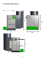
1
GREENFLAME 55/85/100/125/199 kW Commercial Wood Pellet Boiler System INSTALLATION, OPERATION AND SERVICING INSTRUCTIONS Please read these instructions carefully before installing and operating this appliance. TO BE RETAINED BY THE HOUSEHOLDER TR Engineering Ltd TR Engineering Ltd operates a policy of continuous development and improvement of our products and welcome any feedback from our Customers. Please forward your comments to : TR Engineering Ltd Unit 7 Newton Chambers Way Thorncliffe Industrial Estate Chapeltown Sheffield S35 2PH United Kingdom This symbol is used to highlight important information Tel: 0114 2572300 Fax: 0114 2571419 E-mail: [email protected] Web: www.trianco.co.uk SAFETY NOTICE PLEASE READ THIS ENTIRE MANUAL BEFORE YOU INSTALL AND USE YOUR NEW BOILER. THIS APPLIANCE MUST BE INSTALLED BY APPROVED AND COMPETANT PERSONNEL ONLY. FAILURE TO INSTALL THE APPLIANCE IN ACCORDANCE WITH THE MANUFACTURERS INSTRUCTIONS AND LOCAL BUILDING REGULATIONS AND BY-LAWS WILL INVALIDATE THE WARRANTY. Manual Edition : GREENFLAME Commercial Series May 2012 2 Table of Contents 1 1.1 General Information Important note for efficient and low-emission operation of your Greenflame biomass heating system. 5 2 2.1 Safety Information Greenflame Safety Guidelines 7 7 3 3.1 3.2 3.3 3.4 Greenflame System Features Greenflame Boiler Features Fillomatic Pellet Transport Features Self Cleaning Burner Features Control System 9 10 11 12 13 4 4.1 4.2 4.3 4.4 4.5 4.6 4.7 4.8 4.9 4.10 4.11 Installation Setting out the boiler location Unpacking Assembly Flues Flue Pipe Flue Requirements Air Supply Water Connections Electrical Connections Self Cleaning Burner Electrical Schematic Boiler Control Panel Electrical Schematic 14 14 15 16 17 17 19 22 24 28 29 30 5 5.1 5.2 5.3 5.4 5.5 5.6 5.6.1 5.6.1.1 5.6.1.2 5.6.1.3 5.6.1.4 5.6.1.5 5.6.1.6 Digital Control System Buttons LED’s LCD Display Power Display Error Messages Menus User Menu Power Menu Boiler Thermostat Menu Chrono Menu Time & Date Monitor Load Menu 31 31 32 32 34 34 35 35 37 37 37 37 38 38 3 6 Table of Contents 5.6.1.7 5.6.2 5.6.3 Language Menu Keyboard Menu Secret Menu 38 39 39 6 Troubleshooting 40 7 7.1 7.2 7.3 7.3.1 7.3.2 7.3.3 7.3.4 7.3.5 7.3.6 7.3.7 7.3.8 7.3.9 7.3.10 How Does My Wood Pellet System Work Sensors Combustion Process What Happens When I Turn On My Boiler Check-Up Pre-Heating Pre-Load Variable Ignition Stabilisation Run Mode Modulation Mode Standby / Extinguishing / OFF Pump Management Extinguishing When Boiler Is In The OFF State 43 43 43 45 45 45 45 46 46 47 47 48 48 48 8 Operation 50 9 Maintenance 51 10 Commissioning 52 11 Warranty Information 55 12 Fuel 56 13 13.1 13.2 Technical Data Boiler Dimensions Boiler Section 57 58 59 4 1. General Information Dear Customer, We would like to congratulate you on choosing this high-quality product from TR Engineering Ltd. The Greenflame range of wood pellet boilers for commercial / light industrial applications are designed specially with aim of maximising efficiency, reduced CO2 emissions, compact design for installation in the smallest of plant rooms and cutting edge system management features with remote access through the cellular network for remote routine maintenance, as standard. Due to the low-emissions and CO2-neutral heat produced by renewable fuels, you are making a considerable contribution to the protection of the environment and its resources. You have also chosen a product with an elegant line, a refreshing design and perfect workmanship. The outer surfaces require minimum care in day-to-day life and are easy to clean. On the inside, however, is a carefully designed and ultra efficient heat exchanger which has been developed from TR Engineering Ltd’s 40 years of boiler manufacturing experience. At the centrepiece of the system is a self cleaning pellet burner which is at the cutting edge of combustion technology and innovation which guarantees low emissions and high efficiency by maintaining the combustion area in a clean condition. The mastermind of the system is the TR Engineering Ltd Boiler Management System (BMS) control which sets the standard in control engineering. The LCD display with generous graphics and clear-text user management provides brilliantly simple and easy-to-use operation. This new-generation control system together with the self-cleaning mechanism and the automatic de-ash system makes sure that under normal operating conditions (except for boiler maintenance) only occasional emptying of the ash box is necessary – no other tasks are required. This instruction and maintenance manual contains all the information required for trouble-free operation and handling of the system. Please read it carefully. And if you still have any questions, please contact your sales partner. No claims for damages incurred as a result of misuse of the safety, operating or maintenance notes can be accepted. We wish you many years of heating pleasure with your new TR Engineering Ltd Greenflame biomass heating system. Best regards from your TR Engineering Ltd team, We provide heating with a clear conscience! 5 1.1 Important note for efficient and low-emission operation of your TR Engineering Ltd biomass heating system. For efficient and low-emission operation of your TR Engineering Ltd heating system, please follow these instructions: • Only use the fuels specified in this TR Engineering Ltd instruction manual. Only then can a low-emission, economic and trouble-free operation of your heating system be guaranteed. (Section 12) • Carry out maintenance and cleaning work recommended by TR Engineering Ltd on your heating system at regular intervals. Details can be found in the instruction manual in section 9. By doing this, you will not only be ensuring the operational reliability of the heating system but also its efficient and low-emission operation. The best way of caring for your heating system is by taking out a TR Engineering Ltd maintenance contract. Your TR Engineering Ltd Agent will be happy to give you information about this. • Your TR Engineering Ltd heating boiler is adjustable within an output range of 30 to 100% of the boiler’s rated power. A buffer tank / thermal store is recommended and should be correctly sized by your heating engineer. This ensures efficient and low-emission operation of your TR Engineering Ltd heating system. 6 2. Safety Information In the design of the TR Engineering Ltd biomass system, special attention has been placed on safety. However, since the system contains elements which can reach high temperatures, it is essential that several simple, but important rules, are adhered to by the user. 2.1 TR Engineering Ltd Safety Guidelines Please read the instruction manual carefully before starting the system for the first time, and pay special attention to the safety instructions. If something is not clear, please look it up in this operating manual. • Ensure all maintenance doors are closed tightly. • The boiler room should always be locked. • When opening the boiler door make sure that no flue gases or sparks come out. Never leave the boiler door open without supervision. • Make sure that there is sufficient supply of fresh air to the boiler room and avoid frost. • Carry out maintenance work regularly or call your Agent to arrange to have this done. • Always make sure the power is isolated when carrying out maintenance work or opening the control system. • Combustible materials (including fuel) should not be stored in the boiler room, other than the fuel that is required for the operation of the boiler. • Fire extinguishing apparatus should be located near the door of the boiler room. • The boiler may only be run on wood pellet fuel as prescribed in the fuel section of this manual. • Do not carry out any unplanned changes to the settings; do not modify the system in any way without first consulting your local dealer. • The boiler should be switched off the before refilling the fuel silo using a pump truck for blowing pellets into the storage hopper. • In the case of any problems contact your Agent or for Troubleshooting visit www.trianco.co.uk . Legislation stipulates certain devices should be used with automatic pellet boilers which prevent back-burn along the conveying troughs into the fuel store. The following safety precautions are implemented in TR Engineering Ltd systems: • A cell wheel is located between the head of the conveying auger and the combustion area thus helping to prevent back burn. •If the temperature in the pellet feed pipe exceeds an pre-determined safety temperature the a high temperature safety thermostat will send a signal to the controller that a high temperature has been reached and will initiate a safety shut down sequence. 7 HEALTH AND SAFETY PRECAUTIONS Special care must be taken when installing the boiler such that the requirements of the Health and Safety at Work Act are met. Handling Adequate facilities must be available for loading, unloading and site handling. Fire Cement Some types of fire cement are caustic and should not be allowed to come into contact with the skin. In case of contact wash immediately with plenty of water. Asbestos This boiler contains no asbestos. If there is a possibility of disturbing any asbestos in the course of installation then please seek specialist guidance and use appropriate protective equipment. Metal Parts When installing or servicing this boiler care should be taken to avoid the possibility of personal injury. In all cases the installation must comply with current Building Regulations, Local Authority Bye-laws and other specifications or regulations as they affect the installation of the boiler. It should be noted that the Building Regulations requirements may be met by adopting the relevant recommendations given in British Standards BS 8303, BS EN 15287-1:2007 as an alternative means to achieve an equivalent level of performance to that obtained following the guidance given in Approved Document J. Please note that it is a legal requirement under England and Wales Building Regulations that the installation of the boiler is either carried out under Local Authority Building Control approval or is installed by a Competent Person registered with a Government approved Competent Persons Scheme. HETAS Ltd operate such a Scheme and a listing of their Registered Competent Persons can be found on their website at www.hetas.co.uk. 8 3. Greenflame System Features The data plate contains important information on the type designation of the appliance. You will find this on your system mounted on the control panel cover . The boiler is located on the left hand side of the unit with the burner located underneath the integral storage hopper. The fuel is loaded in the integral hopper which has a capacity of 125 kgs, the TR Engineering Ltd Fillomatic pellet transport system which will fill the integral hopper from a remote bulk storage silo. Vacuum Cyclone Unit Removable Access Panel Ash Containers 9 3.1 Greenflame Boiler Features The heat exchanger has been designed and developed to provide maximum efficiency and combustion quality as well as not having to compromise on space. The compact nature of it’s design has allowed the integral hopper to be incorporated as part of the overall unit. The secondary heat exchanger is cleaned by mechanically operated spirals which actuate vertically at pre-determined intervals to clean the tubes. The drop feed burner is fitted to the side of the boiler where the flame fires in a horizontal direction across the combustion chamber. The flue gases are then forced to rise to the top of the chamber and are forced down behind the refractory board which aids in the complete combustion of the flue gases. The flue gases must then rise again through 12 vertical pipes before exiting through the flue chamber at the rear of the boiler and are eliminated through the flue. The flue has an exhaust fan which aids in providing the ideal draft conditions for the appliance to work efficiently and safely. The flue fan is controlled automatically by a vacuum sensor in the combustion chamber which will automatically adjust the exhaust fan to provide the optimum underpressure conditions in the combustion chamber. 10 3.2 Fillomatic Pellet Transport Features The integral hopper has a capacity of up to 125 kgs of pellets. Filling of the hopper is carried out automatically by the Fillomatic pellet transport system. The pellets are auger fed from the base of the hopper to the top of the drop feed pipe where the pellets free fall into a cell wheel and down into the pellet burner. Located in the hopper is a pellet level sensor which lets the system know when the level of pellets has reached a low level and allows the system to re-fill automatically. The design of he Fillomatic system means that pellets can be transported up to 45m horizontally with a 2.4m vertical rise. For each additional 2.4m vertical rise, 10 meters must be taken off the horizontal travel. Vacuum Feed Hose Auger 11 Bulk Storage Hopper 3.3 Self Cleaning Burner Features The self cleaning burner system allows the burner to maintain optimum combustion by maintaining the combustion tube in a clean condition. The cleaning process is activated after each time the system goes into an extinguishing phase (or after a number of run cycles as required). The controller can also be programmed that after a pre-determined number of hours running the system can shut down, clean and then restart . This will prevent any “clinker “ build up in the combustion tube. Cleaning of the burner tube is carried out by compressed air. A mini air compressor charges a storage tank of air and when this has reached the correct pressure a solenoid valve releases a short high pressure jet of air into the burner which clears any clinker or debris into the de-ash augers. If the temperature in the pellet feed pipe reaches a high temperature a safety thermostat will signal the controller to shut down and signal an error “Er 03” on the LCD display to warn of a high temperature occurrence. The combustion fan of the burner regulates the combustion quality and is controlled automatically. The ignition element creates the initial combustion during start up and will turn off when a full flame is detected in running mode. Burner Cleaning Air Tubes Air Accumulator Tank 12 3.4 Control System The TR Engineering Ltd Greenflame Control System leads the way in combustion efficiency and control and is also at the cutting edge in communications technology and providing the user with useful information related to their Greenflame system. The main features of the Greenflame control system include : • Combustion regulation through control of the combustion fan, exhaust fan and auger interval settings. • Safety sensors on the boiler combustion chamber doors, water overheat thermostat and pellet feed pipe safety thermostat. • Pellet level sensor • UPS switch to provide electrical back-up to the Greenflame in the event of a power cut. • Photocell for flame recognition. • Optional heating system or buffer tank management • 02 visualisation through lambda sensor. • Auto-regulation of the draught in the combustion chamber through a vacuum sensor. • Boiler and burner cleaning management. De-Ash management. • Integrated modem for remote access and maintenance and well as providing the user with ON/OFF features and system status though GSm message. 13 4. Installation Careful consideration and time spent planning the boiler room and fuel store will prevent delays when it comes to installing the system. It is recommended that a survey of the plant room should be forwarded to TR Engineering Ltd for review so they can advise the best solution for locating the boiler and fuel transport systems. Contact your local TR Engineering Ltd Representative who will be happy to advise what information the survey should contain. 4.1 Setting out the boiler location The Greenflame system requires minimum clearances around the appliance for servicing and maintenance. These are detailed in the figure below. A minimum of 600mm is required in front of the boiler in order to safely remove the ash pan from the boiler or to clean the combustion chamber. 300mm 400mm 250mm 750mm The boiler must be located on a non-combustible base that is capable of holding the weight of the boiler when full (1700 kg) 14 4.2 Unpacking The TR Engineering Ltd Greenflame Pellet Boiler System is delivered in a single crate. Remove the wooden crate, cardboard packaging, polystyrene packing, and bubble wrap packaging and recycle in the appropriate manner. The following items should accompany you Greenflame pellet boiler system : Fillomatic Pellet Transport System Pellet cyclone c/w door flap sensor. 40-65mm hose clamps to connect flow and return vacuum feed pipes. Auger system – either the Fillomatic standard auger or the Fillomatic floor track system. De-Ash Box Boiler scraper tool Burner scraper tool A4 Manual pack Installation and User Manual Product Registration Card Foil tape to blank de-ash outlet Chimney pipe gasket Hopper/Boiler fixing bolts x 2 Cable ties to tidy cable runs after installation. In the unlikely event that an item is missing then your Agent should be notified within 5 working days in order to issue replacement parts. Missing or mislaid parts notified after 5 working days will incur a charge plus postal costs. The following guidelines should be followed to ensure that the installation of the boiler is carried out in a trouble free manner. Be careful when moving or lifting the boiler as it is heavy and could cause an injury. Use appropriate lifting techniques and equipment for the individual weights of these sections. Take all necessary precautions to prevent damage to external casing. 15 4.3 Assembly The Greenflame is supplied fitted to it’s base permanent base for ease of lifting and assembly. The Greenflame boiler is “plug and play” with just the connection of the flue, hydraulic system and electrical system. The only items that need to be fitted to the Greenflame are the ash box, exhaust fan housing and the pellet cyclone. Commissioning of the Greenflame may only be carried out by TR Engineering Ltd trained personnel or their authorised representatives. 16 4.4 Flues Use stainless steel twin walled insulated flue pipe to flue your Greenflame. An exhaust fan is used to extract the combustion gases from the firebox. This creates a negative pressure in the firebox and a positive pressure in the flue system. The longer the flue pipe and more elbows used in the system, the greater the flow resistance. Because of these facts we recommend using as few elbows as possible and 10 meters or less of flue pipe. Be sure to use wall and ceiling pass through fittings (which are approved for pellet vent pipe ) when going through combustible materials. Be sure to use a starting collar to attach the flue system to the boiler. The starting collar must be sealed to the boiler flue collar with high temp silicone caulking or aluminium tape Any exterior flues (flue pipe exposed to outside ambient temperatures) should be kept to a minimum, due to potential condensation problems. This is especially important in high humidity cold weather climates, such as maritime areas, lake shores, and low river valleys. It is not recommended that the flue has 90 elbows or horizontal sections. If the flue must pass through a wall only 45 elbows may be used TR Engineering Ltd recommend the use of the Therminox range of flues for use With the TR Engineering Ltd pellet boiler system. 4.5 Flue Pipe A flue pipe suitable for use with a class 1 appliance (i.e. an appliance burning solid fuel). is constructed of two layers with insulation between the layers. This insulation reduces the outside surface temperature to allow a minimum clearance to combustibles of 50mm. The sections of pipe lock together to form an air tight seal in most cases; however, in some cases a perfect seal is not achieved. For this reason and the fact that the TR Engineering Ltd operates with a positive vent pressure, we specify that all joints within the structure should also be sealed with clear silicone. NOTE:. Be sure to inspect and clean the exhaust flue system frequently. NOTE: Read and follow all of the flue pipe manufacturers’ instructions on the proper installation and support of the vent pipe. Adhere to all clearances. 17 Chimneys taller than 6m above the connection will require a draft test to determine if the draft is too high. Note: The High Burn Draft should not exceed 50Pa. A draft stabiliser is fitted to the starter flue to counteract a certain amount of excessive draft but additional measures may be required. Creosote Formation and Need for Removal - When wood is burned slowly, it produces tar and other organic vapours, which combine with expelled moisture to form creosote. The creosote vapours condense in the relatively cool chimney flue of a slow-burning fire. As a result, creosote residue accumulates on the flue lining. When ignited, this creosote makes an extremely hot fire. The pellet flue pipe should be inspected at least twice monthly during the heating season to determine if a creosote build-up has occurred. If creosote has accumulated it should be removed to reduce the risk of a chimney fire. Guidance on minimizing creosote formation and the need for periodic creosote removal: The chimney should be inspected during the heating season to determine if a creosote build-up has occurred. If a significant layer of creosote has accumulated (3mm or more) it should be removed to reduce the risk of a chimney fire. The TR Engineering Ltd Boiler may be used and installed into an existing masonry or a flue pipe suitable for use with a class 1 appliance (i.e. an appliance burning solid fuel). It can not be installed in a chimney serving another appliance. The chimney should be cleaned and or inspected before installation. WARNING Keep combustible materials such as grass, leaves, etc. at least 3 feet away from the point directly under the flue termination. (between the flue and the ground) INSTALLATION IS TO BE PERFORMED BY A QUALIFIED INSTALLER. DO NOT INSTALL A FLUE DAMPER IN THE EXHAUST FLUE SYSTEM OF THIS UNIT. DO NOT CONNECT THIS UNIT TO A CHIMNEY FLUE SERVING ANOTHER APPLIANCE. CAUTION KEEP COMBUSTIBLES AWAYFROM FLUE OUTLET. 18 4.6 Flue Requirements A natural draught must exist in the boiler when connected to the flue and this will be checked by the Commissioning Engineer before the burner is run. If this is not the case then the customer must take the necessary measures to ensure a draught like increasing the flue height or fitting an anti downdraught cowl. The proper draught conditions in the flue is critical for the efficient working of wood pellet boilers. TR Engineering Ltd recommend that it’s Therminox range of stainless steel twinwalled insulated flue pipe is used with its “TR Engineering Ltd” boilers. A draught stabiliser is fitted as standard to the short section of flue pipe that connects to the boiler. This will help stabilise draught in average wind conditions. The flue can exit the boiler house/garage through the roof or through the wall by using a bend on the flue. The following diagram indicates recommended flue layouts. Installation must comply with the current Building Regulations and local by-laws and it is the Installers responsibility to ensure that the flue is installed safely and to the appropriate regulations. In order to avoid down draught, the chimney or flue must terminate in a position at least 600mm higher than the highest point on a roof, tree or building within a distance of 9 meters (30 ft.). Down draughts will affect the performance of the boiler and may cause some of the safety features to come into operation. Down Draught: If the proper flue height cannot be achieved the commissioning engineer may refuse to commission the boiler. Whenever possible, the flue should terminate above the apex of the roof; if this is not possible, use a cowl that is specified as anti-downdraught by the cowl manufacturer. Use as few bends as possible but when necessary 135º bends are recommended. In cases where the boiler is commissioned with a lower height flue the necessary draught conditions are achieved on the day of commissioning, the customer must sign the Commissioning Report stating that any issues arising from the flue not to the required height will not be covered under warranty. NOTE: Read and follow all of the flue pipe manufacturers’ instructions on the proper installation and support of the flue pipe. Adhere to all clearances. Reference : BS EN15287-1:2007; Chimneys – Design, installation and commissioning of chimneys; Part 1: Chimneys for non-room sealed heating appliances 19 The chimney or flue must have a cross-sectional area throughout its whole length that is at least the area of flue outlet of the boiler and must be sealed to the boiler with fire clay or other suitable compound. The chimney or flue should be of sufficient height to provide draught of min. 25Pa measured at the test hole in the top of the boiler. Draught conditions that are excessive, measured at the test hole in the top cleaning door of the boiler, due to chimney height or location should be controlled by means of the draught stabiliser fitted to the chimney to ensure a draught of not more than 40 Pa exists. In some instances where the boiler is located in exposed sites a second stabiliser may be required where natural draught exceeds 40 Pa. The newly developed design of the regulator makes it possible to install it on the flue pipe in all possible positions, angled, vertically as well as horizontally. The regulator can be fitted the short flue section supplied with the boiler. Possible leaks can easily be sealed off with a gasket, putty or other suitable sealing substances. Counterbalancing the flap After installation the two screws should be loosened and the balance spindle should be turned to a horizontal position when the flap is closed. Tighten screws. Adjustment of Under-pressure Adjustment of the under-pressure opening the flap is made by pressing the clamp on which the weight is fitted and move it along the spindle. The under-pressure is changed approx. 1 Pa every 2mm the weight is moved, see fig. 2. The values are approximate and must be controlled with a draught indicator if exact under –pressure is required. The flap is set at 25Pa on delivery. 20 Opening of the flap on the regulator differs depending on the adjustment as well as the draught in the chimney. The draught varies considerably depending on the chimney, the weather and if the burner runs or not. This means that the function can vary between different installations, e.g. the flap opens more or less when the burner is running, flutters when the burner starts or a door is being closed, etc. Choice of Materials The materials used in the construction of chimneys and vents should be such that the construction is non-combustible, durable, resistant to temperatures likely to be encountered, to rapid changes in temperature and resistant to external and internal corrosion. Materials for lining vents should have a reasonably smooth finish and thus not unduly impede the flow of the combustion gas products. They should be resistant to potential attacks by flue gases and to spalling. UK regulations state a minimum performance designation for chimneys serving solid fuel appliances as follows: T400 N2 D3 Gxx, where xx is the necessary separation from combustible materials. All flues must be installed in accordance with part J of the building regulations and certified by a competent person. A chimney data plate must be fixed and completed at the base of the flue system before commissioning. In particular it is important to note that the flue gas temp of the TR Engineering Ltd is lower than other solid fuel. In order to ensure the combustion gasses are properly vented the installer must ensure the flue is designed for safe operation. 21 4.7 Air Supply Free Air Requirements - Provision for air for combustion and ventilation: General: A sufficient permanent air supply to the appliance will be required for: (a) Correct combustion of fuel an effective discharge of combustion products to the open air. (b) The ventilation of any confined space in which an appliance is installed to prevent overheating of the appliance and any equipment in and near the appliance. (c) The satisfactory operation of any draught break or stabiliser which may be fitted. It should be both the Architect’s and the installer’s concern that the air required for these functions be introduced so as to cause as little discomfort as possible to building occupants and thus to offer them the least temptation to obstruct ventilation. Air for Combustion: Example • Boiler rating 20 kW • Air for Combustion 550 mm2/kW = 550 * 150 = 82,500 mm2 = 825 mm * 825 mm • Air for Combustion 850 mm2/kW (with stabiliser) = 850 * 150 = 127.500 mm2 = 1275 mm * 1275 mm For boilers fitted with a flue draught stabiliser – first 5kW=300mm2 + 850mm2 per kW above 5kW This requirement will be satisfied if the room or space in which the appliance is installed has an opening or duct which is designed to allow the passage of air at all times equivalent, in total free area, to 550 square mm/kW(2.5 sq. inches per 10,000 Btu's) minimum of the appliance rating. Note ; It is not recommended to fit an extractor fan in the room which contains the Boiler. Air for Ventilation: For an appliance in a confined space, care should be taken to provide air for ventilation. A working guide to the minimum free area of openings to be provided in addition to that for combustion air is as follows: (a) Where the air is taken from a heated space, 1100 sq. mm/kW (5.0 sq. inches per 10,000 Btu's) at low level. (b) Where the air is taken from outside, 550 sq. mm/kW at both high level and low level (2.5 sq. inches per 10,000 Btu's) 22 The warranty for such boilers could be affected if proper free air requirements are not provided. TR Engineering Ltd recommend that two air vents should be provided into the room containing the appliance. One should be located at least 100mm above finished floor level and the other at high level. A single vent at high level may prevent fresh air from reaching the burner if the ambient temperature surrounding the appliance is high. Recommended air vent size into plant room 35,000 mm2 Warning : Never obstruct or cover permanent ventilation openings in the boiler room as these are required for the Safe and efficient operation of the boiler. 23 4.8 Water Connections The diagram below indicates the plumbing connections at the rear of the boiler. Two flow connections and two return connections to run separate circuits to the DHW cylinder and the heating. 2” BSP Flow 1” Drain 2” BSP Return It is recommended that the boiler is plumbed into open vented system (the maximum static head of water permissible is 90 ft. (27.44 meters)), but if it is being connected to a sealed system an appropriately sized expansion vessel should be used and installed as per manufacturers instructions. The expansion vessel should be sized based on the water capacity in the boiler and the water in the entire heating system. Incorrectly sized expansion vessel will invalidate the warranty The pump must be always be placed on the return pipe work just before the boiler. It is recommended that a by-pass pipe between the flow and return is used with a valve to regulate the temperature of the water returning to the boiler. If only one flow and return is required then blank off the unused connections and pipe the flow and return from opposite side of the boiler. An automatic air vent and pressure relief valve must be fitted to the flow pipe work immediately outside the boiler. The pressure relief valve should be piped to a drain to prevent injury to the User or Service Technicians if it is activated. 24 TR Engineering Ltd recommend the use of a buffer tank. Buffer tanks (direct cylinders) can achieve the optimum running of the system in terms of efficiency and running costs. Once the plumbing has been completed the system should be fully flushed to clear any debris which may have become lodged in the pipe work. The system must then be filled and the pump can be run continuously for a few hours to completely de-aerate the system. Only when the system has been fully vented can the boiler be commissioned. The installation and the design of the central heating system must be in accordance with BS EN 14336:2004: Heating Systems in Buildings. Installation and commissioning of water based heating systems. BS EN 12828: 2003; Heating Systems in Buildings. Design of water based heating systems. BS EN 12831: 2003; Heating Systems in Buildings. Method for calculation of the design heat load. 25 26 F&E GREENFLAME Heating Control TR Engineering Ltd Greenflame Boiler with Buffer Tank , Radiators and DHW Circuit on a Sealed System Pipe Layout Concept Diagram Domestic Hot Water Cylinder Hot OUT Heating Zones Cold Mains IN 27 TR Engineering Ltd Buffer Tank Heating Control TR Engineering Ltd Greenflame Boiler with Buffer Tank , Radiators and DHW Circuit on an Open Vented System Pipe Layout Concept Diagram Domestic Hot Water Cylinder Hot Water OUT Heating Zones Cold Mains IN 4.9 Electrical Connections Electrical installations should only be carried out by suitably qualified and certified electricians. If in doubt on any issue relating to the electrical connections on the appliance contact TR Engineering Ltd Energy Technical Support or your Local Dealer for guidance before carrying out any connections. The Greenflame boiler is powered by a 230V 50 Hz electrical supply which should be protected with a 5A fuse. It is recommended that a power isolation switch is located adjacent to the boiler to isolate the power during servicing and maintenance but also out of the reach of children and to prevent accidental turning off of the mains power. Only authorized TR Engineering Ltd personnel may open the control panel on the boiler. Any interference with the wiring in the control panel will invalidate the warranty. The boiler and complete plumbing system must be adequately earthed and bonded in accordance with local Building Regulations and Bye-Laws. 28 Safety Thermostat Photocell 5 4 3 2 1 11 10 9 8 7 Combustion Fan Air Cleaning Solenoid 29 6 12 Core Cable Ignition Element 4.10 Self Cleaning Burner Electrical Schematic 4.11 Boiler Control Panel Electrical Schematic 30 5. Digital Control System The BMS (Boiler Management System) controls all functions of the boiler and associated hardware (i.e. circulation pump, mini hopper auger motor, exhaust fan, etc.). The control panel display indicates the system state at which the boiler is running in real time as well as providing the Customer with a user friendly way of adjusting temperature and identifying clearly any issues which may occur system. The control panel display is laid out as follows : P1 P4 ESC P2 L1 L2 L3 P3 P5 # L4 L5 L6 L7 L8 L9 L10 L11 L12 SET P6 5.1 Buttons FUNCTION DESCRIPTION Button ON/OFF Function: Ignition, Extinguishing by pushing the button for 3 seconds until the acoustic signal. UNBLOCK Function: unblock. When the system is in Block or Error by pushing the button for 3 seconds until the acoustic signal. MODIFY VALUES INTO MENU In modify mode change menus and submenus values. RUN ON MENU AND SUBMENU In Menu run on submenu and menu. P4 P6 ESC Function Exit managed pushing the button if in a menu or a submenu. Out of menu “Pump Test” P1 MENU •Function: Enter in menu or in a submenu. MODIFY •Enter in modify mode into a menu. SET •Save data in a menu. ENABLE CHRONO PROGRAMMING •In Chrono menu -> Chrono Program : enables the selected program. 31 P2 P3 P5 5.2 LED’s FUNCTION Led DESCRIPTION HEATING RESISTANCE Led On: Resistance on L1 AUGER 1 Led On: Auger in the interval ON L2 PUMP Led On: Pump On L3 ELECTROVALVE Led On: Electrovalve On L4 PELLET LEVEL Led On: sensor reveals a lack of pellet L10 EXTERNAL THERMOSTAT Led On: Ambient Thermostat contact open OR High Voltage Ambient Thermostat not supplied with 230Vac L11 FLOWSWITCH Led On: flow switch contact closed L12 5.3 LCD Display Chrono enable System State Locked Buttons Day and Time Power Recipe Flame Status G Mar 14:26 P2 Ignition Pellet 1 102 Error Code Er19 36 Exhaust Temperature Leds Boiler Temperature 32 65 Boiler Thermostat Information that can be seen on the Main Screen is: Date and Time Chrono activation Modality (D daily, W weekly, We week-end) Locked buttons User power selected or Automatic Power Selected recipe Functioning State System Error code Boiler Thermostat value Exhaust temperature Water temperature Flame On if Flame Light over L01 Functioning State that can be seen on the Main Screen is : Check Up Preheating Preload Ignition Fix Ignition Stabilization Run Mode Modulation Standby Extinguish Recover Ignition Block Other information that is presented by the display : Out of Fuel: The message is displayed if the Pellet Sensor reads a lack of Fuel Cleaning: The message is displayed during the extinguishing phase of the Start-Stop program (if this function is activated). Prob: The message is visualized during Check Up (starting cleaning) if one or more of the sensors is 0 °C or 0 lum (photo resistance) or if one or more probes are unconnected or short-circuited. This is not an error, but only a visualization . Door: The message is displayed if the door contact is open. 33 5.4 Power Display DISPLAYED POWER IN AUTOMATIC MODE DISPLAY DESCRIPTION Po No power (OFF state or BLOCK state) or fans at max speed in CHECK UP state Pa Variable Ignition or Stabilization Power P1 Power 1 P2 Power 2 P3 Power 3 P4 Power 4 P5 Power 5 Pe Extinguishing, Modulation or Standby Power 5.5 Error Messages ERRORS DISPLAY DESCRIPTION Er01 Error activation Safety thermostat High voltage 1 Also with the system OFF Er02 Error activation Pressure switch (Only with the Exhaust fan ON) Er03 Error activation Pellet thermostat High voltage 2 Er04 Water over-temperature Er05 Exhaust over-temperature Er09 Real time clock error Er12 Ignition failed Er13 Accidental Extinguishing for low brightness of the flame (The photo probe reads a light under value L00 - Light OFF) Er16 Lack of voltage Er19 Extinguishing for Lack of Pellet 34 5.6 Menus In the BMS there are two levels of Menu , a USER MENU and a SECRET (INSTALLER) MENU. The USER MENU allows the User to perform some basic functions such as: 5.6.1 User Menu USER MENU DESCRIPTION Power Allows to User modify the combustion power if the controller is set to Manual Mode Boiler Thermostat Menu which allows the User to modify the Boiler Standby temperature Chrono Modality o Disabled o Daily o Weekly o Week-end Menu used to select the functioning mode of the internal time clock in the BMS system. Chrono Program o Daily o Weekly o Week-end Menu which allows the User to program 3 periods of time to switch on and switch off the boiler for each programming mode. Time and Date Menu to select time and date Monitor Smoke Temperature Water Temperature Flame Light Ignitions’ N Product Code Menu to display the temperatures and other values Load Menu which allows to load the auger. (Used only on commissioning and during auger cleaning). Language Menu which allows to change the languages Keyboard Menu Menu to test the connection and to update the panel (see section Learn Menu) System Menu Menu to enter into Secret Menu 35 To Enter the User Menu : Push P3 button to enter the user menu Using P4 and P6 buttons it is possible to select the desired menu or submenu. If a parameter value is changed, the new value is sent to the boiler controller. But if the transmission failures a message appears: and you need to modify again the parameter’s value. Push P1 button to exit the menu. : 36 5.6.1.1 Power Menu Menu which allows the User to modify the system combustion power only if the system is set to Manual by the Commissioning Engineer 5.6.1.2 Boiler Thermostat Menu Menu which allows the User to modify the Boiler Thermostat’s value for Standby i.e. boiler SET temperature. The minimum and maximum valves are factory set but are modifiable by the Service Technician.. 5.6.1.3 Chrono Menu Menu which allows to set the times to switch on and switch off the boiler. It is recommended that the boiler is controlled by a time clock locate in the dwelling. If the “built in” time clock system is required you Agent should be able to give you detailed information on it’s use. 5.6.1.4 Time & Date Menu which allows to set date and time. 37 5.6.1.5 Monitor Menu allows you to view the values as read by the system sensors. 5.6.1.6 Load Menu Menu allows you to load the auger manually. To enable the auger select ON To stop the auger select OFF or wait 600 seconds. (The seconds of activation are showed on the display) IT IS POSSIBLE TO LOAD THE AUGER MANUALLY ONLY IF THE SYSTEM IS OFF. NOTE: ONLY RUN THE AUGER WHILE THE PLASTIC FLEXI-PIPE IS DISCONNECTED FROM THE PELLET FEED PIPE. 5.6.1.7 Language Menu This menu allows you to change the language version on the display. 38 5.6.2 Keyboard Menu This menu allows Technicians to test the panel connection and to update the product. Only Authorised Personnel should access this Menu. 5.6.3 Secret Menu This menu is for Service Technicians and Commissioning Engineers and contains all the parameters and settings for the system. This menu is password protected. 39 6. Troubleshooting Error Code Er 01 Cause Remedial Measures Error Activation Safety Thermostat High Voltage 1 Mechanical High Limit Thermostat tripped due to high Check that boiler is completely full of water. water temperature Check if the temperature is set too high and reduce if required. Check that the circulation pump is working. Re-set the manual high limit thermostat by removing the black cap and pressing the re-set button. Hold the ON/OFF button for 3 seconds and the error will clear. If unsuccessfull inform Customer Service or your Local Agent Er 02 Error Activation - Pressure Switch. In models fitted with a pressure switch in the When closing the door check that the door makes a good seal. combustion chamber, a lack of underpressure or Check that the exhaust fan is working. draught will result in an error. Hold the ON/OFF button for 3 seconds and the error will clear. If unsuccessfull inform Customer Service or your Local Agent Er 03 Error Activation - Pellet Thermostat High Voltage 2 Heat tavelling back through the pelletpellet feed pipe. Check that the exhaust fan is working and creating draught. Check for any obstructions in the flue ways and clean as necessary. Re-set the manual reset button on the pellet feed stat on the burner. Hold the ON/OFF button for 3 seconds and the error will clear. If unsuccessfull inform Customer Service or your Local Agent Er 04 Water Over Temperature Water temperature in the boiler has reached 95° C Check that boiler is completely full of water. Check if the temperature is set too high and reduce if required. Check that the circulation pump is working. Re-set the manual high limit thermostat by removing the black cap and pressing the re-set button. Hold the ON/OFF button for 3 seconds and the error will clear. If unsuccessfull inform Customer Service or your Local Agent 40 Error Code Er 05 Cause Remedial Measures Exhaust Over-Temperature Flue gas temperature has reached 482°F Check that the ceramic board in the combustion chamber is not damaged. Clean down the surfaces of the combustion chamber. Check the calorific value of the fuel. Hold the ON/OFF button for 3 seconds and the error will clear. If unsuccessful inform Customer Service or your Local Agent Er 09 Real time clock error The back up battery in the control panel has expired. Er 12 Inform Customer Service or your Local Agent Ignition Failed Ignition has failed or the pellets have failed to ignite. Clear any un-burned pellets from the burner tube with the scraper provided. Check that there are enough pellets in the hopper. Check that the pellets are free from dust. Remove the auger and empty pellets and dust. Replace and refill with pellets. Check that the heating element is glowing after the pre-heating phase. Remove the photocell and check that it is clean. Hold the ON/OFF button for 3 seconds and the error will clear. If unsuccessful inform Customer Service or your Local Agent Er 13 Accidential extinguishing due to low flame. The flame has become low during Run or Clear any un-burned pellets from the burner tube with the scraper Modulation mode. provided. Check that there are enough pellets in the hopper. Check that the pellets are free from dust. Remove the auger and empty pellets and dust. Replace and refill with pellets. Remove the photocell and check that it is clean. Hold the ON/OFF button for 3 seconds and the error will clear. If unsuccessful inform Customer Service or your Local Agent Er 16 Lack of Voltage The electrical supply has been interrupted for more Clear any un-burned pellets from the burner tube with the scraper than 10 seconds. provided. Hold the ON/OFF button for 3 seconds and the error will clear. 41 Error Code Er 19 Cause Remedial Measures Lack of Pellet The level of pellets in the hopper has run low. Re-fill hopper with pellets. If the time clock is still in the ON position the system will restart automatically. If the time clock is in the OFF position the system will stay OFF until the time clock is turned ON. 42 7. How Does My Wood Pellet System Work ? The TR Engineering Ltd Biomass Heating System introduces state of the art technology to a very simple process. The basic steps of how the system works are illustrated later in this chapter. 7.1 Sensors On the TR Engineering Ltd system there are 8 sensors which provide the Boiler Management System with the information it requires to control the processes. These are : •Flue Gas Temperature Probe - measures the temperature of the exhaust gases in the flue. •Water Temperature Probe - measures the temperature of the water in the boiler. •Photocell - measure the light value (flame) in the burner. •Pellet Level Sensor - gives a signal to the controller when the hopper has reached a low level of pellet. •Burner Cleaning Sensor - gives a signal to the controller when the cleaning mechanism on the burner has fully retracted. •Door Switch - gives a signal to the controller that the ash pan door is open. •Pellet Feed Safety Thermostat - signals the controller if the temperature in the pellet feed pipe reaches an unsafe temperature. •High Limit Safety Thermostat - signals the controller if the water temperature has reached an un-safe temperature. 7.2 Combustion Process The combustion process to ignite and burn wood pellets cleanly and efficiently is summarised on the following flow chart : 43 Functioning State Process Active Components Heat Pre-Heating (this is provided by the ignition element) Pre-Load (wood pellets are introduced into the pellet burner) Fuel Ignition Stage 1 Variable Ignition (hot air from the ignition element is directed at the pellets to initiate the first stage of ignition) Ignition Stage 2 Stabilisation (the flame is developed from a weak early stage flame to a more intense flame by the addition of extra air from the combustion fan ) •Heating Element ON •Heating Element ON •Auger ON •Heating Element ON •Auger ON (at intervals) •Exhaust Fan ON •Combustion Fan ON •Heating Element ON •Auger ON (at intervals) •Exhaust Fan ON •Combustion Fan ON Run Mode Run (once the photocell reads enough light and the flue gas temperature is above a prescribed temperature the system enters RUN mode) •Auger ON (at intervals) •Exhaust Fan ON •Combustion Fan ON Modulation Mode Modulation Standby Extinguishing (when the water temperature rises within 5 C of set point the boiler will start to reduce to a lower power level that will maintain the water temperature at just below the set point) •Auger ON (at intervals) •Exhaust Fan ON •Combustion Fan ON Standby / Extinguishing (if in Modulation mode the boiler still reaches the set point it will extinguish and enter STANDBY. If the controller gets a signal to turn OFF the system will extinguish and enter the OFF state) 44 •Exhaust Fan ON •Combustion Fan ON 7.3. What happens when I turn on my boiler ? When the TR Engineering Ltd boiler is given an signal to turn on (either by a remote time clock which is usually in the house or switched on at the digital controller at the boiler) the system goes through a series of steps : 7.3.1 Check Up Time : Approx 15 seconds (TIMER t08) This stage allows for the cleaning of the boiler and burner before the ignition phase. The combustion fan on the burner and the exhaust run at full power to eliminate any dust or smoke (in the event of a hot restart) form the boiler. The Belimo valve opens the burn back protection plate. All the system sensors are checked for correct connections. 7.3.2 Pre-Heating Time : 40 seconds (TIMER t00) This stage brings the ignition element to the correct temperature before loading the burner with pellets. 7.3.3 Pre-Load Time : Approx 40 seconds (TIMER t38) A pre-defined starting dose of pellets is given into the burner by the auger. 45 7.3.4 Variable Ignition Time : 4 minutes (TIMER t02) This stage starts the ignition process. The heat from the ignition element is directed at the pellets by the combustion fan which runs at a relatively slow speed. At intervals the auger introduces more pellets once the flame has begun to establish. The photocell monitors the light level as the flame develops. The flue gas temperature probe measures the temperature in the flue. At the end of this stage the photocell checks to make sure the flame intensity is over a pre-defined level and the flue gas temperature is over a pre-defined temperature. If both of these variable are satisfied then the process continues to the next stage (Stabilisation) If these variables are not satisfied then this stage continues for another 3 minutes (second ignition attempt) and if the variables have not reached their values by the end of the second attempt, EXTINGUISHING will occur and an Er12 (Failed Ignition) will be displayed on the screen). 7.3.5 Stabilisation Time : 60 seconds (TIMER t03) This stage develops the flame even further before allowing the system to enter RUN mode. The auger introduces pellets more frequently into the burner. The combustion fan and exhaust fan increase in speed to speed up the combustion process. The ignition element remains on in this stage. At the end of this stage the photocell checks to make sure the flame intensity is over a pre-defined level and the flue gas temperature is over a pre-defined temperature. If both of these variable are satisfied then the process continues to the next stage. (Run mode) If these variables are not satisfied then this stage continues for another 3 minutes (second ignition attempt) and if the variables have not reached their values by the end of the second attempt, EXTINGUISHING will occur and an Er12 (Failed Ignition) will be displayed on the screen. 46 7.3.6 Run Mode During run mode the combustion rates are pre-set for the 5 different power levels. On entering this phase the system starts at Power Level 1 and after a 20 second intervals increases a Power Level each time until Power 5 is reached. The boiler will continue to run at Power 5 until the water temperature reaches within 5 C of the set point. The ignition element is off during this phase. The auger ON/OFF values are pre-set for each of the power levels. During commissioning the combustion fan and exhaust fan speeds are fan are set to maintain the correct CO2 (Carbon Dioxide) and CO (Carbon Monoxide) levels for clean efficient combustion. The circulation pump is activated by the controller once the water in the boiler reaches 55 C. The pump will turn off once the temperature drops to 52 C. If the unlikely event that light diminishes below a pre-set low value for a period of time then Er13 will appear to indicate that the light has gone out. This may be due to a lack of pellets entering the combustion tube due to dust or poor quality pellets. 7.3.7 Modulation Mode The modulation range has been pre-set so that the system starts reducing to a lower power level when the water temperature comes within 5 C of the set point. Example : Water temperature on the controller has been set to 70 C. When the water temperature in the boiler reaches 65 C the system enters Modulation Mode. When the water temperature reaches 66 C the power level drops to Power 4, 67 C – Power 3, 68 C – Power 2, 69 C – Power 1 and 70 C – Standby / Extinguishing. During Modulation each power level has it own pre-set parameters for fan speeds and auger ON/OFF values. Power Level 5 is the full rated output of the boiler. Power Level 1 is 30% of the rated output of the boiler. Depending on the heat loss from the heating system the boiler may settle at a power level to match the heat loss from the system and may increase power levels again to match a drop in water temperature. The Modulation band may be set wider (up to a max of 15 C) by the Commissioning Engineer if it is deemed necessary 47 7.3.8 Standby / Extinguishing / OFF The system goes into STANDBY when the water in the boiler reaches it set temperature and the system goes into an extinguishing mode. The auger stops feeding pellets to the burner. The Belimo valve closes the burn back protection plate. The combustion fan and exhaust fan will run at full power until all light in the burner has extinguished and the temperature in the flue has decreased to a safe temperature. Once the flame has been extinguished the system enters it’s Final Cleaning stage where the burner cleaning and boiler cleaning takes place (if applicable). The system will sit in standby until the water temperature decreases to a pre-determined temperature when it will restart again with the CHECK UP phase. The system will go into the OFF state when the system gets a signal from an external time clock or if the system is turned off manually on the controller. The shut down procedure is the same as STANDBY. Once the extinguishing phase has been completed the boiler will remain in the OFF state until a signal is given to the boiler to start. 7.3.9 Pump Management The circulation pump on the plumbing system (not supplied) is controlled by the controller. It is programmed to activate when the water temperature in the boiler reaches 55 C and to shut off when the temperature decreases to 52 C. In cold conditions when the boiler is OFF the pump will activate when the water temperature in the boiler drops to 5 C to prevent the water from freezing. “ICE” will appear on the display. 7.3.10 Extinguishing when boiler is in the OFF state If the boiler goes into an extinguishing mode when the boiler is off it is because the photocell is receiving light (the ash pan door may be opened or in a very bright boiler room some light may be reflected on to the photocell.) Once the light has been eliminated the boiler will remain in the OFF state. 48 CAUTION: Hot while in operation. Do not touch. Keep children, clothing, furniture, and other combustible material out of the installation clearance area. WARNING: Do not operate with chamber or ash removal doors open. Always ensure that the combustion chamber door on the boiler is fully shut after attending to the boiler. WARNING: Do not store fuel or other combustible material within installation clearance area. WARNING: Do not operate the boiler if there is the possibility that any part of the plumbing system may be frozen. WARNING: Do not use an aerosol spray near the boiler when it is in operation. 49 8. Operation The TR Engineering Ltd Wood Pellet Heating system is designed with the user in mind. The system is fully automatic and only requires occasional intervention by the user. The system can be operated by a remote time clock, in the house or elsewhere, or by a room thermostat. Once the time clock/room thermostat is turned on the system will automatically start, run, modulate and shut down as the water within the system reaches it’s set temperature. Once the controller detects a drop in temperature the boiler will restart as long as the time clock or room thermostat are still calling for heat. As mention in the previous section the basic controls on the display are : Turn ON /OFF (Manually over ride the remote time clock or room thermostat) Hold the ON/OFF button (P2) for 3 seconds to start the boiler manually. To turn off the boiler repeat the process. If the boiler is turned OFF during the ignition phase then the system will finish out the ignition stage run for a few seconds and then shut down. If the boiler is turned ON during the shut down / extinguishing stage the system will go into RECOVERY IGNITION, i.e. the system will restart once the extinguishing process has finished. Set the boiler temperature. The boiler temperature is factory set to 65 C but can be set by the User to a minimum of 55 C up to a maximum of 85 C. The set the water temperature : •Press SET button (P3) on the display. •Use or to scroll up or down through the menu until you reach Boiler Thermostat. •Press SET to select Boiler Thermostat •Press SET to adjust the temperature by using the or buttons and press SET to save the selected temperature. •Press ESC (P1) twice to return to the main screen. Warning Note Properly installed, operated and maintained this appliance will not emit fumes into the dwelling. Occasional fumes may occur if the appliance doors are opened while the boiler is under fire. However, persistent fume emission is potentially dangerous and must not be tolerated. If fume emission does persist, the following immediate actions should be taken:•Switch off the appliance fan (if fitted) •Open doors and windows to ventilate room. •Let the fire out or eject and safely dispose of fuel from the appliance. •Check for flue or chimney blockage, and clean if required. Do not attempt to relight the fire until the cause of the fume emission has been identified and corrected. If necessary seek expert advice. 50 9. Maintenance As with all wood pellet heating appliances periodic maintenance is required to be carried out by the User and an annual service by you local Agent. WARNING: When carrying out periodic maintenance allows allow the boiler to cool down sufficiently after being shut down before opening the ash pan door. Always wear heat resistant gloves and protective clothing when handling ash. Householder Maintenance Ash Box / Ash Pan The ash box (in automatic de-ash models) only needs to be emptied approx 3-4 months (depending on boiler usage). In non-automatic de-ash models the regular ash pan may need to be emptied every 2 weeks (depending on boiler usage). After the installation of the TR Engineering Ltd pellet heating system it is recommended to observe the level of ash over a number of weeks to establish how frequent the ash containers need to be emptied. The ash box should fill to within 2” of the lid. The regular ash pan should fill to the top of the sides of the ash pan. Burner It is recommended that whenever the combustion area door is open that the burner tube is scraped clean with the scraper tool provided. The Commissioning Engineer will demonstrate this to you. Boiler It is recommended that whenever the ash pan area door is open that the side walls of the boiler are brushed clean with the scraper tool provided. The Commissioning Engineer will demonstrate this to you. Annual Service It is recommended that the TR Engineering Ltd pellet boiler system is serviced annually or every 1200 hours, whichever comes first. Your local Agent will advise you on the cost of the service and will advise you what maintenance contracts are available in your area. 51 10. Commissioning Commissioning may only be carried out by TR Engineering Ltd authorised personnel. The digital control panel shall remain locked until all pre-commissioning checks have been carried out and the Commissioning Engineer. A pre-commissioning checklist must be submitted by the installer to the Local Agent prior to a visit by the Commissioning Engineer. The Commissioning Engineer will carry out a series of checks on the installation and the appliance prior to commissioning. Should the Engineer find that some installation items remain outstanding or if there are items that may present a health and safety risk he may decide to not commission the appliance until recommendations have been carries out. The return visit by the commissioning by the Engineer will incur a call back charge. Your local Agent will advise you of these charges. Automatic De-Ash Models : Make sure that the foil tape provided is attached to the inside of the de-ash box so that the auger opening is covered. Failure to do so will lead to inaccurate adjustment of draft and flue gas analysis. Cover opening with foil tape Commissioning can be divided into 3 separate tasks : 1. Pre-commissioning checks 2. Start up check 3. Run mode check and flue gas analysis 52 1. Pre-commissioning checks These checks include : Electrical installation o.k. Flue installation o.k. Plumbing at the boiler is o.k. Unlock the controller Boiler system test Load boiler hopper with pellets Check de-ash auger is covered if applicable. 2. Start Up Check Turn on boiler Monitor draught and adjust at each stage of ignition (25 Pa draught) Ensure all functions are operating correctly Monitor photocell and flue gas temperature reading during start up Monitor the transition from start up to running mode 3. Run mode check and flue gas analysis. Ensure boiler reaches power 5. Set boiler to manually adjusted power levels Check draught. Run for approx 15 minutes until flue gas temperature reaches working temperature. Carry out flue gas analysis. Adjust combustion fan to achieve CO2 reading of approx 12% and CO of less than 300 ppm Repeat the process for power levels 4,3,2 and 1. Return the boiler to automatically adjusted power levels. Wait until boiler reaches the water temperature to enter modulation range and boiler modulates successfully, reaches water set temperature and shuts down. During the operation of the boiler is it recommended that you check for any leakage of products of combustion from the flue system or from service openings on the boiler 53 • Customer User Instructions – Turning ON/OFF the boiler – Adjusting water temperature – Control Panel – Loading the auger if it has run out of pellets – Managing error messages – Emptying the ash pan – Cleaning the boiler – Cleaning the burner – Cleaning the auger • Health & Safety Information – Handling hot ash – Protective equipment – Electrical • Customer Acceptance – Customer signs commissioning certificate to confirm that they have received instruction on how to use the appliance and are aware of the Health & Safety implications and procedures for handling hot ash. Customer also confirms that they understand the warranty and call back policy of TR Engineering. 54 11. Warranty Information TR Engineering Ltd offer the following guarantees / warranties on this appliance : 5 year replacement warranty on the boiler shell against leaks. 12 months replacement warranty on all electrical components i.e., photocell, fans, thermostats, controller, display panel. The above items are covered under a parts and labour guarantee. Exclusions The warranty excludes all ancillary products associated with the system ( e.g. flue pipes, circulation pumps, bulk hoppers and augers, plumbing and electrical system.). The ash pan, fibre board and ignition elements are regarded as a consumable item and are not covered under warranty. The warranty does not cover Third Party damage to the product or damage caused by the plumbing (an example would be an inappropriately sized expansion vessel) or electrical system. Warranty does not cover issues arising from pellets that do not conform to CEN TS 14961, O Norm standard ON 7135 or DIN Plus 51731. Recommendations advised to the Customer to be carried out during commissioning must be completed and advised to your local Dealer in order to validate the warranty. The requirements for the flue installation, particularly in relation to draught, is the responsibility of the system owner. Compliance with Local Building Regulations must be adhered to. The warranty does not cover misuse of the product or sabotage. Any consequential loss or damage caused by the failure of a component on this product is not covered. Call Out Policy. All call out requests should be communicated by fax or e-mail to our Technical Support Dept. or your Local Dealer stating clearly the following information : The exact nature of the problem / defect and any error messages on the display. The boiler serial number and model. In the event that telephone instructions can correct the problem the system user will be provided with the appropriate instructions. If deemed necessary temporary instruction may be given to minimise the problem. Should a service call be deemed necessary the Technical Support Dept. or your Local Dealer will advise the procedure involved in scheduling a visit by a Service Technician. If the issues / defects are deemed to be covered under warranty then no charge will apply. Maintenance contracts for our wood pellet products are available from your Local Dealer 55 12. Fuel For the correct operation and efficient working of your wood pellet boiler system TR Engineering Ltd recommend that only pellets that conform to European-wide CEN TS 14961 standard are used with their products. The system settings are for the use of 6mm pellets only. It is the responsibility of the Customer to ensure that only a quality grade pellet is used for the appliance. Issues arising for poor quality pellet and which necessitates a visit by a Technician is not covered under warranty and a call out charge will apply. If you change your fuel brand or supplier contact your local servicing / commissioning engineer (or TR Engineering Ltd) for guidance on whether the burner needs to be adjusted. Pellets must be stored in a dry and well ventilated storage area free from moisture. Incorrect storage of pellets may degrade the pellet quality and may affect the performance of the burner. In cases where the pellets appear to have a high fines/dust content the auger system may need to be cleaned periodically to maintain the correct feed rate of pellets to the system. Some pellet brands may require the burner to be cleaned at regular intervals to remove any residues which may be left behind. Wood fuels that conform to the European-wide CEN standard means that the product is of the highest quality and that the consumer can have every confidence in choosing wood heating. CEN, the European Committee for Standardisation, established a Technical Committee to define standards for solid biofuels. Recommended Specification for Wood Pellets for Domestic Heating: Origin: Chemically untreated wood without bark Moisture content: ≤10 % Dimensions: ≤ 6 mm ± 0.5 mm and L ≤ 5 x Diameter or ≤ 8 mm ± 0.5 mm, and L ≤ 4 x Diameter Ash content: ≤ 0.7% Sulphur content: ≤ 0.05 % Mechanical durability: 97.5% after testing Amount of fines: ≤ 2.0 % Additives: < 2 w-% of dry basis Energy density: Min. 4.7 kWh/kg. EU Standards : CEN TS 14961 Austria: ÖNORM M1735 Sweden: SS 187120 and SS 187121 Germany: DIN 51731 56 13. Technical Data Greenflame Specification GREENFLAME GREENFLAME GREENFLAME 55 85/100/125 199 1552 1690 1900 Width A mm Height B mm 1540 1940 1940 Depth C mm 1178 1323 1500 Fuel Hopper Capacity kgs 152 125 125 Boiler Flue Pipe Diameter mm 152 200 200 Dry Weight Empty kgs 750 1950 1000 litres 160 410 280 Operating Temperature - Water °C 50 - 85 °C 50 - 85 °C 50 - 85 °C Nominal Output kW 16.5 - 55 27 - 125 55 - 199 Nominal Fuel Input kW TBC 138 TBC Reduced Fuel Input (30%) kW TBC 30 TBC Efficiency Nom. Input (EN303-5) * % 90 90.4 90 Smoke Temp at Nominal Power °C 165.3 183 180 Smoke Temp at Reduced Power °C 106.2 110 110 Min. Required Draft Pa 10 10 10 Exhaust mass flow g/s 15.7 – 28.7 Recommended Operating Pressure bar 1.5 1.5 1.5 Maximum Operating Pressure Bar 3 3 3 Water Flow Connection Inch 1.5” 2" 2” Water Return Connection Inch 1.5” 2" 2” Boiler Drain Inch 1” 1" 1” °C 105 105 105 Class Class 3 Class 3 Class 3 6” 8” 8” Water Content Boiler Safety Thermostat Setting Boiler Class Flue Size Boiler Power Requirement Max. Electrical Consumption Line Voltage Fuse Protection (Controller) PCB Fuse Protection 43 - 102 230V - 50 Hz / 15.3 Amp kW </= 1.5 </= 1.5 </= 1.5 Amp 6.3 6.3 6.3 Amp 15.3 15.3 15.3 * EN303-5 - Heating boilers for solid fuels, hand and automatically fired, nominal heat output of up to 300kW 57 13.1 Boiler Dimensions 1442 1817 1786 750 58 1275 340 206 1215 1085 TR Engineering Ltd Unit 7 Newton Chambers Way Thorncliffe Industrial Estate Chapeltown Sheffield S35 2PH United Kingdom Tel. : 0114 2572300 Fax : 0114 2571419 E-mail : [email protected] Web : www.trianco.co.uk © TR Engineering Ltd Copyright in this brochure and the drawings and illustrations contained in it is vested in TR Engineering Ltd and neither the brochure or any Part thereof may be reproduced without prior written consent. TR Engineering Limited’s policy is one of continuous research and development. This may necessitate alterations to this specification. 400003 Issue 1 May 2012