1
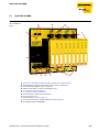
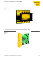
Connections and components of the DPC-49-4RMB
3.3.6
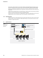
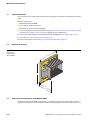
Power supply concept
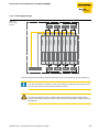
Figure 10:
Power supply
concept
Seg1
ADU
Pwr A
Pwr B
1A
1B
Seg1
Seg2
2A
Host
2B
Seg2
Seg3
3A
Field
3B
Seg3
Seg4
4A
4B
Seg4
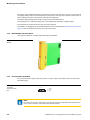
The power supply and the power supply modules DPC-49-IPS are designed for system redundancy.
Note
Each host connection is limited to 21 mA. If your simplex or redundant host requires more
than 21 mA, it must be connected to the field connection.
Attention
The voltage supply Pwr A (here: yellow) supplies the left power supply module of the
segment. The voltage supply Pwr B (here: gray) supplies the right power supply module of
the segment.
D301164 0312 - FF Diagnostic Power Conditioner System
3-7