1
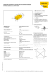
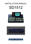
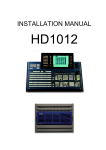
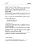
InclinoMeters
with IO-Link
technology
Parametrization
Sense it! Connect it! Bus it! Solve it!
Inclinometers with IO-Link technology –
General information
1 General information
Please read this section carefully. Safety aspects cannot be left to chance when dealing
with electrical equipment.
These instructions contain the necessary
information for the commissioning and
parametrization of the inclinometer series
B2N360 from TURCK. It specifically addresses trained and qualified personnel disposing
of the appropriate technical knowledge.
Prescribed use
The devices described in this manual must
only be used in the prescribed way and only
with certified components and devices from
third party manufacturers.
Appropriate transport, storage, deployment
and mounting as well as careful operating
and thorough maintenance guarantee the
troublefree and safe operation of these devices.
2
Hans Turck GmbH & Co. KG • Tel. +49 208 4952-0 • Fax +49 208 4952-264
Inclinometers with IO-Link technology –
Contents
Inclinometers B2N360 – with IO-Link technology
[email protected] • www.turck.com • 2013/06
1 General information................................................................ 2
2 Description of the IO-Link technology................................. 4
3 Commissioning and parametrization................................... 5
4 Parametrization via teach function...................................... 6
5 Parametrization via PACTware™ and IODD......................... 7
6 General technical data............................................................. 12
7 Technical data IO-Link............................................................. 13
3
Inclinometers with IO-Link technology –
Description of the IO-Link technology
2IO-Link technology
An IO-Link system consists of IO-Link devices (sensors or actuators), a standard sensor/
actuator cable and an IO-Link master. An
IO-Link master can feature one or several ports. Only one IO-Link device can be
connected at each port. IO-Link is therefore
a point-to-point communication and not a
fieldbus.
2.1.1 SIO mode
If the sensor operates in SIO mode it can
be run via a standard input module, for
which an IO-Link master is not required.
Thereby Pin 2 can be used as a switching
output, Pin 5 and Pin 6 as analog outputs.
Pin 4 is configured as a switching output and
can also be used for IO-Link communication.
2.1Operating modes
TURCK inclinometers can be operated
in SIO mode (standard I/O mode) or in
IO-Link communication mode. After
power up the device is always in SIO mode.
2.1.2 IO-Link communication mode
In order to run the sensor in IO-Link mode,
the sensor must be connected to an
IO-Link capable module (master). The sensor operates in COM2 mode at 38.4 Kbaud.
The IO-Link communication between the
sensor and the master is implemented
via Pin 4. The output on pin 2 retains its
functionality. Process data (cyclic), service
data (acyclic) and events are transferred in
communication mode. Furthermore, the
sensor can be parameterized in communication mode via the master.
For detailed information on the sensor parameters see the parameter lists.
4
Hans Turck GmbH & Co. KG • Tel. +49 208 4952-0 • Fax +49 208 4952-264
Inclinometers with IO-Link technology –
Commissioning
3 Commissioning
For the connection of the inclinometer
to the IO-Link master, use the adapter cable RKC 8.4T-1.5-RSC4T/TX320, ident no.
6625002 (sensor side M12, 8-pin, IO-Link
master side M12, 4-pin).
The ports of the IO-Link master can be
configured differently. If a port is set to SIO
mode, the master at this port behaves like
a normal digital input. If the port is set to
communication mode, it tries to find the
connected sensor. This process is called the
wake up process. For this read also the manual for your IO-Link master.
If the sensor is in IO-Link mode, it can be
parameterized via the master. For this read
chapter 7
Parametrization using PACTware™ and
IODD
PACTware™ is an open platform in which
any fieldbus device manufacturer can integrate the operation of their devices.
PACTware™ uses a standard interface between the frame program and the individual software modules for operating devices.
Only in this way can modern user-friendly
operating concepts be implemented.
Parametrization using the teach function
The inclinometer can be set via the teach
function. Pin 8 is used as teach input, whereby
the inclinometer is parametrized by bridging
Pin 8 and Pin 3 (GND) or Pin 8 and Pin 1
(UB). For simple teaching use the optionally
available teach adapter TX3-Q20L60 with
the ident no. 6967118. With the switches
you can activate the teach inputs.
The connection between the sensor and PC
is established via the USB-IO-Link master. In
order to operate the Turck inclinometer via
PACTware™, you also need the IODD interpreter and sensor-specific IODD in addition
to the PACTware™ software. These tools can
be obtained from the TURCK website. The
standard display of PACTware™ enables the
sensor to be read and set easily.
For more details and specific parameter
information see the parameter lists. More
information about the PACTware™ software
is provided at www.turck.com.
[email protected] • www.turck.com • 2013/06
5
Inclinometers with IO-Link technology –
Parametrization via teach function
4Parametrization via teach function
Parameters
Teach input
LED
To adjust the zero point offset and the measuring range, position the sensor accordingly.
Zero point offset (see notes
on p. 7)
bridge Pin 3 (GND) and Pin 8 for 5 s
yellow LED flashes – after 1 s steady – after 3 s flashes – after 5 s
steady
Measuring range start,
x-axis (see notes on page 7)
bridge Pin 1 (UB) and Pin 8 for 1 s
green LED flashes – after 1 s steady
Measuring range end,
x-axis (see notes on page 7)
bridge Pin 1 (UB) and Pin 8 for 3 s
green LED flashes – after 1 s steady – after 3 s flashes
Measuring range start,
y-axis (see notes on page 7)
bridge Pin 3 (GND) and Pin 8 for 1 s
yellow LED flashes – after 1 s steady – after 3 s flashes
Measuring range end,
y-axis (see notes on page 7)
bridge Pin 3 (GND) and Pin 8 for 3 s
yellow LED flashes – after 1 s steady – after 3 s flashes
Preset mode
Preset angular ranges
bridge Pin 1 (UB) and Pin 8 for 10 s
bridge or press the button within 10 s or the device exits
this mode automatically
green LED flashes – after 10 s steady
-10°…+10°
bridge Pin 3 (GND) and Pin 8 once briefly
yellow LED flashes once
-45°…+45°
bridge Pin 3 (GND) and Pin 8 twice briefly
yellow LED flashes twice
-60°…+60°
bridge Pin 3 (GND) and Pin 8 three times briefly
yellow LED flashes three times
-85°… +85°
bridge Pin 3 (GND) and Pin 8 four times briefly
yellow LED flashes four times
Preset mode Functions
bridge Pin 1 (UB) and Pin 8 for 10 s
bridge or press the button within 10 s or the device exits
this mode automatically
green LED steady – after 10 s flashes
Mode 1 "upper hemisphere" ± 90°, default setting
bridge Pin 1 (UB) and Pin 8 once briefly
green LED flashes once
Mode 2 "lower hemisphere" ± 90°
bridge Pin 1 (UB) and Pin 8 twice briefly
green LED flashes twice
Mode 3, 2 × 360°
bridge Pin 1 (UB) and Pin 8 three times briefly
green LED flashes three times
Mode 4, X: 0…360°, Y: off
bridge Pin 1 (UB) and Pin 8 four times briefly
green LED flashes four times
Mode 5, Y: 0…360°, X: off
bridge Pin 1 (UB) and Pin 8 five times briefly
green LED flashes five times
Filter setting mode
bridge Pin 3 (GND) and Pin 8 for 10 s
bridge or press the button within 10 s or the device exits
this mode automatically
yellow LED steady – after 10 s flashes
Filter A, 24 Hz (for programming
adapter Q20L60),
default setting
bridge Pin 3 (GND) and Pin 8 once briefly
yellow LED flashes once
Filter B, 15 Hz
bridge Pin 3 (GND) and Pin 8 twice briefly
yellow LED flashes twice
Filter C, slower but less susceptible Filter
bridge Pin 3 (GND) and Pin 8 three times briefly
yellow LED flashes three times
Default setting
bridge Pin 3 (GND) or Pin 1 (UB) and Pin 8 for 15 s
after 15 s yellow and green LED alternate fast
6
Hans Turck GmbH & Co. KG • Tel. +49 208 4952-0 • Fax +49 208 4952-264
Inclinometers with IO-Link technology –
Parametrization via PACTware™ and IODD
NOTE
Please note that with changing the zero point you also change the start and end point of the measuring range accordingly. In the
"upper hemisphere" and "lower hemisphere" mode the zero-point can only be offset if the measuring range stays within the defined
spreads of 0°…90°, 0°…270°, 180°…90° or rather 180°…270° (see Fig. 2, on page 8).
5Parametrization via PACTware™ and IODD
You can download PACTware™, the IODDinterpreter and the inclinometer IODD-file
from www.turck.com.
Once you have installed PACTware™, activate the "IODD_IOL_B2N360-Q42.zip" file
with the IODD-interpreter and update the
device catalog in PACTware™.
You need the following hardware components:
■■B2N360-Q42… (the sensor to be parametrized)
■■IO-Link master
■■Adapter cable RKC8.4T-1,5-RSC4T/TX320;
Ident no.: 6625002
Depending on the application requirements, you should parametrize and test the
appropriate filter setting using PACTware™.
Three filter settings can be specified (Filter
A, B, C). For each of these settings you can
choose from over 30 different filter values.
Under the menu item "Active filter" you can
finally select the active filter setting.
These three filter settings (Filter A, B, C) can
also be set via teach function (see previous
page 6) without IO-Link communication.
5.1 Configure system
Under the menu item "Operation Mode" you
can either configure the sensor as an inclinometer or as accelerometer (see also page
11). You can set different lowpass filters.
Faults of different frequency ranges can thus
be suppressed.
[email protected] • www.turck.com • 2013/06
7
Inclinometers with IO-Link technology –
Parametrization via PACTware™ and IODD
5.2 Configure angle
Under the menu item "Mounting position"
you can adapt the sensor to the respective
application. In default status (upper hemisphere) the sensor provides output values in
the tilt position of 5 V or 12 mA as the zero
point for the X and the Y axis. All six possible
mounting positions can be configured with
this output behaviour. For example, if the
connector should face upwards, this can be
set under this menu item.
The menu item "Functional area" provides
five possible functions (see also programming via teach function, page 6):
The factory default assignment of the axes is
shown in the following figure:
Upper and lower hemisphere are defined as
follows
1 Upper hemisphere (see fig. 2)
2 Lower hemisphere (see fig. 2)
3 (2 × 360°)
4 (360° X)
5 (360° Y)
2 Lower hemisphere
The sensor provides the possibility to capture all angles from 180°…90° or rather
180°…270° via the X and the Y-axis.
0°
-90
270°
Y
90°
X
180°
Fig. 1: Assignment of axes
1 Upper hemisphere
This function is the default setting.
The sensor provides the possibility to capture all angles from 0°…±90° via the X and
the Y-axis.
NOTE: In PACTware™ , angles are specified
as absolute values between 0°…359.99°.
Entering negative areas is therefore not possible. The following are the standard measuring ranges:
±45° = 315°…45°
±60° = 300°…60°
±30° = 330°…30°
±10° = 350°…10°
Fig. 2: Definition of the upper and lower hemisphere
3 (2 x 360°)
The sensor captures the entire angular range
of 0°…360° via the X and the Y-axis. Please
observe, however, that owing to the principle involved, the analog output signals may
mutually influence each other.
4 (360° X)
The X-axis is output over the entire range
(0°…360°). The Y-axis is turned off.
5 (360° Y)
The Y-axis is output over the entire range
(0°…360°). The X-axis is turned off.
8
Hans Turck GmbH & Co. KG • Tel. +49 208 4952-0 • Fax +49 208 4952-264
Inclinometers with IO-Link technology –
Parametrization via PACTware™ and IODD
5.3 Configure analog outputs
Use the menu item "Output type" to define
the analog output either as current or voltage output.
"Start value" or "End value" are the limit values of the analog output. These can be chosen freely between 0 mA and 20 mA or 0 V
and 10 V. It is also possible for example to
select an output range of 0…10 mA.
In the menu item "Overrange behaviour"
you determine how the sensor behaves in
case of exceeding the set measuring range.
You can adjust that the limiting value is either held or that an error beep is issued.
[email protected] • www.turck.com • 2013/06
In the menu item "Direction of rotation"
you can select between "clockwise CW" and
"counterclockwise CCW" rotation.
The "Lower limit" and "Upper limit" of the
measuring range define the active area of
the sensor. For instance, if you want to parameterize a detection range of ±30°, here
you can set 330° (lower limit) and 30° (upper
limit) in "clockwise direction of rotation.
If the sensor is mounted on a flat surface
where the slope is used as the zero point
(5 V or 12 mA), this can be done by selecting
the menu item "Zero point offset teach".
To enter values for movement of the zero
point select the menu item "Zero point offset" (see also teach function page 6).
You can also use the current tilt position of
the sensor for the upper and lower limit. You
can make these settings in the menu item
"Teach start position of measuring range"
resp. "Teach end position of measuring
range (see also teach function on page 6).
9
Inclinometers with IO-Link technology –
Parametrization via PACTware™ and IODD
5.4 Configure digital outputs
Pin 2 and pin 4 of the inclinometer can be
used as a switching output.
The switchpoint and the hysteresis are defined as follows under "Digital Outputs" as
output 1 (Pin 2) and output 2 (Pin 4).
In "Referring axis" you specify which axis (X
or Y) is used for the determination of the
switchpoint.
10
In "Output type" you can select between
PNP and NPN switching function.
In "Teach switchpoint ON" and "Teach
switchpoint OFF", the current inclined positions are taken to define the hysteresis.
In addition, you can parametrize a "hysteresis" (0.01° or greater) for the switchpoints or
select the switching behaviour in the menu
item "Inverting".
In "Switchpoint ON" or rather "Switchpoint
OFF" you enter the angular range for the
hysteresis in plain text.
Hans Turck GmbH & Co. KG • Tel. +49 208 4952-0 • Fax +49 208 4952-264
Inclinometers with IO-Link technology –
Parametrization via PACTware™ and IODD
5.5 Configure "acceleration"
The operating modes "Inclination" and "Acceleration" are selected in the system configuration (see also page 7).
In the selection "Acceleration X/Y linear" the
acceleration is output as an analog signal
separately in the X and Y-direction. The detectable acceleration values are ±2 g, with
the initial value being 0 V or rather 0 mA
with -2 g, 5 V or rather 10 mA, with 0 g and
10 V or rather 20 mA with 2 g.
The following top view Fig. 3 shows the corresponding acceleration:
In the operating mode "Acceleration 2D" or
"Acceleration 3D" the sensor uses the analog
output (Pin 5). The direction of the acceleration is not taken into account, only the value
is issued. Fig. 4 shows the corresponding acceleration "2D"; Fig. 5 for "3D". The following
values can be determined 0 g = 0 V or rather
0 mA to 2 g = 10 V or rather 20 mA.
In addition, a switching output can be defined as threshold logic, i.e. if the freely selectable threshold value is exceeded, the
output switches through for at least 1 second.
Fig. 4: Directions of acceleration 2D (top view)
x
y
Fig. 5: Directions of acceleration 3D (top view)
Fig. 3: Directions of acceleration X/Y linear (top view)
[email protected] • www.turck.com • 2013/06
11
Inclinometers with IO-Link technology –
Technical data
6Technical data
42,5
42,5
ø 5,3
LED
M12 x 1
52
22,85
2
67,7
Measuring range specifications
Measuring range
Measuring range x-axis
Measuring range y-axis
Wiring diagram
0…360°
0…360°
0…360°
System
Resolution
Repeatability/accurancy
Linearity deviation
Temperature drift
Ambient temperature
16 bit
≤ 0.03 %, depending on filter setting
≤ 0.2 % of full scale
≤ ± 0.015 % / K
B2N360-Q42-E2LiUPN8X2-H1181: -25…+70 °C
B2N360-Q42-E2LiUPN8X2-H1181/S97: -40…+70 °C
Electrical data
Operating voltage
Residual ripple
DC rated operational current
Rated insulation voltage
Short-circuit protection
Wire breakage/reverse polarity protection
Output function
Voltage output
Current output
Load resistance voltage output
Load resistance current output
Sampling rate
1
2
3
4
5
6
7
8
UB
out
GND
out/IO-Link
X-out
Y-out
n.c.
teach
B2N360-Q42-E2LiUPN8X2-H1181: 15…30 VDC
B2N360-Q42-E2LiUPN8X2-H1181/S97: 7…30 VDC
≤ 10 % Upp
≤ 150 mA
≤ 0.5 kV
yes
yes/entirely
8-wire, NO/NC , PNP/NPN, analog output
0…10 V
4…20 mA
parametrizable via IO-Link, e.g. 0…20 mA
ï 4.7 kW
≤ 0.4 kW
500 Hz
Housing
Housing style
Dimensions
Housing material
Connection
Vibration resistance
Shock resistance
Protection class (IEC 60529/EN 60529)
MTTF
rectangular, Q42
67.5 × 42.5 × 42.5 mm
plastic, PA 12-GF30
male, M12 × 1
55 Hz (1 mm)
30 g (11 ms)
IP68/IP69K
159 years acc. to SN 29500 (Ed. 99) 40 °C
LED indication
Power-on indication
Switching status
12
1 × LED green
1 × LED yellow
Hans Turck GmbH & Co. KG • Tel. +49 208 4952-0 • Fax +49 208 4952-264
Inclinometers with IO-Link technology –
Technical data IO-Link
7IO-Link – Technical data
Physics
Physics 2 (3-Wire)
Com-Type
Standard: COM 2 (38400 Baud)
Frametype
Frametype 2.2
7.1 Parameter data
You can read and write to the sensor via the IO-Link parameter dataset.
7.1.1 System parameters (System Command)
Restarting the communication.
Index (hex.)
Index (dez.)
R/W
Function
0x02
2
W
1: restart
7.2.2 Identification
The following parameters can be read out:
■■Manufacturer's name
■■Manufacturer text
■■Product name
■■Product ID
■■Product text
■■Serial number
■■Hardware version
■■Firmware version
The following parameter can be read out and set:
■■Specific name of the application
Index (hex.)
Index (dez.)
R/W
Function
0x10
16
R
Manufacturer's name
0x11
17
R
Manufacturer text
0x12
18
R
Product name
0x13
19
R
Product ID
0x14
20
R
Product text
0x15
21
R
Serial number
0x16
22
R
Hardware version
0x17
23
R
Firmware version
0x18
24
R/W
Specific name of the application
[email protected] • www.turck.com • 2013/06
13
Inclinometers with IO-Link technology –
Technical data I/O-Link
7.1.3 Analog process data
Here, you can read out the angle in X-direction and Y-direction.
Index (hex.)
Index (dez.)
R/W
Function
0x40
64
R
Measuring angle X
0x41
65
R
Measuring angle Y
7.1.4 Teach in
The following teachable parameters can be read or written.
Index (hex.)
Index (dez.)
R/W
Function
0x70
112
R/W
Operation 1: Inclination/(2: Vibration)/3: Acceleration XY/4: Acceleration 2D
0x71
113
R/W
Lowpass filter A, 0…30, 255: Disabled
0x72
114
R/W
Lowpass filter B, 0…30, 255: Disabled
0x73
115
R/W
Lowpass filter C, 0…30, 255: Disabled
0x74
116
R/W
Active filter: 1…3
0x75
117
R/W
Angle compensation 0 OFF; 1 ON
0x80
128
R/W
Configuration analog output X, 1: I/2: U
0x81
129
R/W
Configuration analog output X, "Start value" in mV / 0.001 mA
0x82
130
R/W
Configuration analog output X, "End value" in mV / 0.001 mA
0x83
131
R/W
Overrange behaviour X 1: End value/2: error beep
0x84
132
R/W
Configuration analog output X, rotation direction 1: CW/2: CCW
0x85
133
R/W
Start position measuring range X entry in ° × 100, defined between 0…36000
0x86
134
W
Start position measuring range X measurement of current angle,
1: Recording of measured value
0x87
135
R/W
End position measuring range X entry in ° × 100, defined between 0…36000
0x88
136
W
End position measuring range X measurement of current angle,
0x89
137
R/W
Zero point reference X entry in ° × 100, defined between 0…36000
0x8A
138
W
Zero point reference X measurement of current angle,
0x8B
139
R/W
Zero point reference acceleration XY: X entry
0x8C
140
W
Zero point reference acceleration XY: X measurement of current value,
1: Recording of measured value
1: Recording the measured value
1: Recording of measured value
0x8D
141
W
Zero point reference acceleration XY X, 1: Reset
0x90
144
R/W
Configuration analog output Y, 1: I/2: U
0x91
145
R/W
Configuration analog output Y, "Start value" in mV / 0.001 mA
0x92
146
R/W
Configuration analog output Y, "End value" in mV / 0.001 mA
0x93
147
R/W
Overrange behaviour X 1: End value/2: error beep
0x94
148
R/W
Configuration analog output Y, rotation direction 1: CW/2: CCW
0x95
149
R/W
Start position measuring range Y entry in ° × 100, defined between 0…36000
0x96
150
W
Start position measuring range Y measurement of current angle,
1: Recording of measured value
0x97
151
R/W
End position measuring range Y entry in ° × 100, defined between 0…36000
0x98
152
W
End position measuring range Y measurement of current angle,
1: Recording of measured value
14
Hans Turck GmbH & Co. KG • Tel. +49 208 4952-0 • Fax +49 208 4952-264
Inclinometers with IO-Link technology –
Technical data I/O-Link
continued on next page
Index (hex.)
Index (dez.)
R/W
Function
0xA0
160
R/W
Switching output 1 axis, 1: X/2: Y
0xA1
161
R/W
Switching output 1 type NPN/PNP, 1: PNP/2: NPN
0xA2
162
R/W
Switching output 1 ON entry in ° × 100, defined between 0…36000
0xA3
163
W
Switching output 1 ON measurement of current angle, 1: Recording of measured value
0xA4
164
R/W
Switching output 1 OFF entry in ° × 100, defined between 0…36000
0xA5
165
W
Switching output 1 OFF measurement of current angle, 1: Recording of measured value
0xA6
166
R/W
Switching output 1, hysteresis in ° × 100, defined between 0…36000
0xA7
167
R/W
Switching output 1, inversion of switching range
0xA8
168
R/W
Switching output 1, enter threshold 0 …2000 mg, acceleration XY, X-direction
0xA9
169
R/W
Switching output 1, enter threshold 0 …2000 mg, acceleration 2D
0xAA
170
R/W
Switching output 1, enter threshold 0 …2000 mg, acceleration 3D
0xB0
176
R/W
Switching output 2 axis, 1: X/2: Y
0xB1
177
R/W
Switching output 2 type NPN/PNP, 1: PNP/2: NPN
0xB2
178
R/W
Switching output 2 ON entry in ° × 100, defined between 0…36000
0xB3
179
W
Switching output 2 ON measurement of current angle, 1: Recording of measured value
0xB4
180
R/W
Switching output 2 OFF entry in ° × 100, defined between 0…36000
0xB5
181
W
Switching output 2 OFF measurement of current angle, 1: Recording of measured value
0xB6
182
R/W
Switching output 2, hysteresis in ° × 100, defined between 0…36000
0xB7
183
R/W
Switching output 2, inversion of switching range
0xB8
184
R/W
Switching output 1, enter threshold 0 …2000 mg, acceleration XY, Y-direction
0xC0
192
R/W
Selection of the functions 1: upper hemisphere; 2: lower hemisphere; 3: 2 × 360°; 4: 360° X;
5: 360° Y
0xC1
193
R/W
Mounting position,1: Normal; 2: 90° Y; 3: 180°; 4: 270° Y;5: 90° X; 6: 270° X
7.1.5 Factory reset
Index (hex.)
Index (dez.)
R/W
Function
0xCF
207
W
1: Factory Reset
[email protected] • www.turck.com • 2013/06
15
Hans Turck GmbH & Co. KG
45472 Mülheim an der Ruhr
Germany
Witzlebenstraße 7
Tel. +49 (0) 208 4952-0
Fax +49 (0) 208 4952-264
E-Mail [email protected]
Internet www.turck.com
D102018 2013/06
*DD102018ßß2013/06*
www.turck.com