1
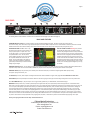
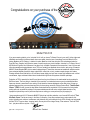
Congratulations on your purchase of the
Model TSC-618
If you are a session guitarist, you’re “not-quite A-List” until you have a Tri-Stereo-Chorus in your rack! It is the single most
identifiable and certainly the lushest stereo chorus ever made, heard on tons of recordings from Joni Mitchell to Don
Henley, Madonna to Eric Clapton...Lukather to Landau. Made for a brief time during the 80's and released under the
Dyno My Piano, Songbird, and Dytronics names, it went through many circuit changes. Just what is a Tri-Stereo-Chorus?
My Electronic Engineer John Greene and I are two of only a handful of people who can answer that. I own 6 of them and
have documented and repaired dozens more. TSC’s are actually three separate chorus circuits, each using a Panasonic
MN3007 Bucket Brigade (BBD) chip to create its delayed signal. These three choruses are treated with multiple modulations and mixed together across the stereo output field in a way that, not only, creates complex images, but creates
Phasing artifacts as well. Add to this a 30 volt internal power supply, and you have a super high-headroom rack unit that
sounds warm, huge, and doesn’t distort when interfaced with high-level rack systems and studio patchbays.
Production of TSC’s ceased in the late 80’s, and since then the price of these on the used market has skyrocketed to
$4000 and more. The funny thing is, almost all of the ones that I’ve checked out were so poorly maintained that often
times one channel or more wasn’t even working! It’s all about the trimmer adjustment on the delay chips..if those are
adjusted improperly they can sound weak and noisy. And now along comes the Fulltone Custom Shop “That 80’s Rack
Chorus” (TERC for short) to save the day. Better constructed than the orginal but 100% the same circuit using better
quality parts such as metal film resistors in the power-related areas for less noise, and gold plated sockets on key
opamps that (should they ever fail) will be as simple as us mailing you a new part and you just popping it in.
I have sourced enough N.O.S. Panasonic MN3007 Delay chips to build a production run of around 3200 units of "That
80's Rack Chorus” and to service any in the future, if necessary. I have also produced many custom parts for this
project, including pots, switches, transformers, and photocells, but just the thought of only 3200 of these ever being made
with the T.E.R.C. logo one them... drawing heavily from my love of the vintage Looney Tunes cartoons "That's all Folks"
font... just puts a smile on my face. Enjoy!
C
2014 FMP Inc. All Rights Reserved
Michael Fuller / President
Page 2
FRONT PANEL
1
2
3
4
5
6
7
8
9
10
11
12
The following features contain references to numbers found on both the Front Panel (Page 2) and Back Panel (Page 3)
FRONT PANEL FEATURES
LINE / INSTRUMENT button (diagram feature #1): Line level devices are items such as amplifier effects loops, recording consoles & patchbays, or other Pro
Audio devices. Push button IN to select LINE LEVEL, which reduces the input 12dB and raises the output 12db. This switch does not change the volume, but you
will notice a serious increase in noise/hiss unless you are interfaced with proper LINE LEVEL devices. If interfacing with line level devices, always leave this
button pushed IN so as to not distort or damage the TERC’s preamp. NOTE: If plugging the guitar directly in to your TERC (jack 21), always have LEVEL switch to
OUT position for INSTRUMENT level operation.
PEAK L.E.D. (#2): This LED will light up if the preamp is overloaded by the incoming signal. It is unlikely that you will ever see this light up, as the TERC has a 30
volt power supply, offering 3.3 times more headroom than any 9 volt powered device.
EFFECT ON/OFF BUTTON (#3): Push button IN for EFFECT-ON, push to OUT for EFFECT OFF. The TERC is not true-bypass and is structured for 1:1 gain,
neither boosting nor cutting the overall volume.
OUTPUTS STEREO / MONO BUTTON (#4): There are 3 analog Chorus Circuits in a TERC: Left (L), Right (R), and Center (C). With this button pushed IN to
STEREO, the L OUTPUT (#17 & 18) emits signal from the L & C Chorus circuits only, and the R OUTPUT (#19 & 20) emits signal from the R & C circuits only.
With this button switched OUT (MONO mode) the L, R, and C Chorus circuits all sum evenly to both the L and R OUTPUTS. NOTE: If you are simply plugging
your guitar in to the TERC and on to only one amp you would use MONO mode (button OUT) and connect the amp cable to either one of the L or R outputs.
PRESET MODE (feature #5): This is the classic Tri-Stereo-Chorus slow chorus sound. PRESET mode only happens when the PRESET button is IN and the
MANUAL button (#6) is OUT. You will notice that the INTENSITY knobs and the SPEED knob do not function when the PRESET is selected. NOTE: make sure
MANUAL button (#6) is OUT or you will hear BOTH the PRESET and the MANUAL sounds at the same time!
MANUAL MODE (#6): MANUAL mode happens when the PRESET button is OUT and MANUAL button is pressed IN. In MANUAL mode the L, R and C
INTENSITY knobs (f#7,8, 9) and the SPEED knob (feature #10) are functional. NOTE: make sure PRESET button is OUT.
Combining PRESET & MANUAL modes: Yes, by pressing IN both PRESET (#5) and MANUAL (#6) mode buttons, you can combine all the different Low
Frequency Oscillators (LFO’s) for all sorts of possibilities. It’s amazing to hear the PRESET mode’s slow swirl with a fast speed selected in the MANUAL mode on
top of that.
INTENSITY knobs (#7, 8, & 9): The knobs ONLY function when the MANUAL knob is pressed IN. Turning these Clockwise (CW) will increase the chorus effect
level, with the deepest chorus being around 12 o’clock to 1 o’clock. Chorus is created by taking the original signal, processing that signal through a delay and
modulating (pitchbending) it, then mixing the original and the processed signals back together. The strongest chorus sounds you can get are when the orginal and
processed signals are mixed together equally with a 50/50 balance, the “chorus” is created by these original and processed signals fighting against each other!
Once you change the balance so that the processed signal gets louder than the original signal, you are only hearing the processed signal... which is what we call
VIBRATO. Therefore, when any of the TERC’s INTENSITY knobs are past 1 o’clock your will be hearing mostly the pitchbend vibrato from those channels,
something Michael Landau made famous during his “Raging Honkies” Band period.
SPEED knob (#10): This knob only operates when the MANUAL mode button is pressed IN. Turn it CW to increase the rate of the modulation, turn it counter
clockwise (CCW) to decrease the modulation rate. It has a ridiculously wide range of available speeds, and you can turn it (CCW) to a point where it is so slow the
entire modulation cycle takes five seconds or more to complete. You will hear both Flange and Phase effects at lower speeds, especially with the INTENSITY
knobs around 12 o’clock.
OUTPUT LED’s (#11): These L & R LED ladders monitor the OUTPUT signal from your TERC. It is not uncommon to see these jump up to the +3 dB area, please
make sure your signals are adjusted so that it only briefly visits the red, otherwise distortion will occur.
POWER switch (#12): Press this IN to turn on the power to your TERC. If it does not light up RED, check if the power cable is plugged snuggly in to the power
cable receptacle (#13) or check the fuse, which is located in the power cable receptacle (#13) on the back of the TERC.
C
2015 FMP Inc. All Rights Reserved
Page 3
BACK PANEL
13
14
15
16
17
18
19
20
21
The following features contain references to numbers found on both the Front Panel (Page 2) and Back Panel (Page 3)
BACK PANEL FEATURES
POWER RECEPTACLE / FUSE (#13): Accepts a standard computer-type IEC detachable Power Cable. The cable is included for US & Canada only.
To access the 0.3amp, 5mm x 20mm fuse, simply unplug the IEC power cord from the TERC’s receptacle and use a small flat blade screwdriver to press down on the tab
located inside the cutout area under the middle pin. Press down on this tab and the fuse door will pop open, then grab it with your fingers and pull out.
OPERATING VOLTAGE: All TERC’s have a 3 tap
transformer primary that can be quickly wired for any
country’s power. Tap #1 is for Japan and is “100”
volt. Tap #2 is marked “115” and can be operated off
of anywhere between 110 to 120 volts, USA &
Canada. Tap#3 is marked “230” and can be operated
off of anywhere between 220 and 240 volts, for
Europe. You will see this listed on the voltage info
area (#14) and there are additional voltage decals
(place at #14) included with your manual should this
voltage ever get changed.
HOW TO CHANGE VOLTAGE: Warning! This procedure
should ONLY be performed by a competent, qualified
technician. Any damage that results from this procedure will
void your warranty and may cause injury. Unplug the power
cable from the wall. Unplug the power cable from the power
receptacle. Open the enclosure by remove all of the small
screws around the sides of the TERC, and the one tiny screw
holding the top section down near the front panel. Inside you
will see a yellow wire (see below diagram), simply unsolder
that wire, move it to the appropriate voltage for you country,
and resolder.
EXTERNAL SPEED JACK (#15): You can attach an external variable speed control pedal to your TERC. This pedal must have a standard 100K B taper potentiometer in it
to operate correctly. NOTE: You must have the TERC’s SPEED knob (#10) set to FULL CW position or the external speed controller will not operate!
EXTERNAL CANCEL (#16): This jack allows you to externally cancel the Chorus effect, but you will still be running through the TERC’s preamp circuitry.
It is a typical “Tip to ground cancels” jack.
1/4” OUTPUTS (#17 and 19): These outputs are configured unbalanced for standard shielded mono (guitar cable) plugs. Do not use TRS balanced cables here!
XLR OUTPUTS (#18 and 20):XLR outputs are “balanced” with Pin2 “Hot” and Pin1 going to chassis ground to avoid the grounding issues found in many other devices.
1/4” / XLR COMBO INPUT (#21): This jack accepts 1/4” mono (guitar cable) (unbalanced), 1/4” Balanced TRS, and XLR Balanced plugs.
WARRANTY: Fulltone products carry a Limited 5 year Warranty to the original owner with proof of purchase the product was bought new from an authorized Fulltone
dealer. There is no need to register your product, simply keep a copy of your original sales receipt. The Warranty covers failure due to manufacturing errors only and is void
if a mod or repair is attempted by anyone other than Fulltone (or an authorized Fulltone Repairman) and/or if we deem that any operator-caused abuse or damage has
occurred. Things that would cause voiding of the Warranty would include: the use of an incorrect power supply, water damage, physical abuse, etc. If you are having
a technical issue please do not call. Instead, email [email protected] to troubleshoot the problem and (only after troubleshooting) for the scheduling of your repair.
After we have decided that a repair is necessary, we will email you an Acrobat PDF copy of our Return Authorization Form. (RA Form) You then print it out, fill out all the
information, and include it in the box with the effect you are sending. Fulltone Musical Products Inc. is not responsible for and injuries and/or damages related to the use of
our products. The Customer is always responsible for any shipping costs, VAT, duties, or Taxes that may result from the international shipping during sale or repair.
Thank you for buying the Fulltone Custom Shop “That 80’s Rack Chorus!”
Fulltone Musical Products Inc.
11018 Washington Blvd.Culver City, CA 90232 USA
Sales: [email protected]
Repairs: [email protected]
website: www.fulltone.com