1
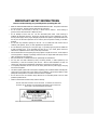
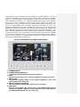
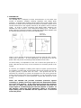
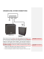
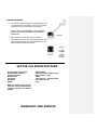
Through my years of playing, experimentation and searching for that great
guitar tone, I pioneered the use of the guitar subwoofer. The VECTOR 210
continues that tradition of an active guitar subwoofer designed to enhance
and expand your guitar tone. The VECTOR 210 is designed to be used with
your existing guitar rig with either a line level input or connected to the
speaker output of your guitar amplifier and add that extra impact and huge
bottom end that you can only get by using a subwoofer. Enjoy this new
dimension of your guitar sound.
Steve Lukather
IMPORTANT SAFTEY INSTRUCTIONS
Please read the following very carefully before operating this unit
•
•
•
•
•
•
•
•
•
•
•
•
READ ALL INSTRUCTIONS CAREFULLY BEFORE OPERATING THIS UNIT. Keep these instructions
for future reference. Heed all warnings and follow all instructions.
Do not use this unit near water, in the rain, or where there is moisture. If this warning is
ignored a serious electrical shock or death may occur.
Do not attempt to service this unit. No user serviceable parts inside. Refer servicing to
qualified, ISP approved personnel. Servicing is required when the unit is damaged in any way,
such as power supply cord or plug is damaged, liquid has been spilled or objects have fallen into
the unit, the unit has been exposed to rain or moisture, does not operate normally, or has been
dropped.
Do not block any ventilation openings on the unit. Do not install near heat sources such as
radiators, heat registers, stoves, or other apparatus that produces heat.
Do not defeat the grounding pin on the power plug. A grounding type plug has two blades and
a third grounding prong. If the grounded plug does not fit in your outlet, please consult an
electrician for replacement of the outlet, which may be obsolete.
Care should be taken to avoid getting any foreign objects or liquid into this unit. Avoid exposure
of this equipment to dripping or splashing and ensure that no objects filled with liquid, such as
vases, are placed on the equipment.
Only use accessories or attachments that are specified by the manufacturer.
Use only with the caster attachment, stand, connecting bracket, or table specified by the
manufacturer, or sold as an accessory with the unit. When a caster attachment is used, use
caution when moving the cart/apparatus combination to avoid injury from tipping over.
To completely disconnect this unit from the AC mains, disconnect the power supply cord plug
from the AC receptacle.
This active speaker system has internal power amplifier(s) and a heatsink located internally with
cooling ports on the back of the unit for airflow over the heatsink. Care should be taken to avoid
placing this active speaker in a location where the airflow is impeded.
Do not drive the unit into excessive heavy distortion for an extended period of time to avoid
premature speaker failure.
Failure to follow these instructions may void the warranty.
THIS UNIT CONTAINS POTENTALLY LETHAL VOLTAGES. TO PREVENT ELECTRIC SHOCK
OR HAZED, DO NOT REMOVE THE POWER AMPLIFIER MODULE, INPUT PANEL OR AC
INPUT PANEL. NO USER SERVICABLE PARTS INSIDE.
REFER SERVICING TO QUALIFIED ISP TECHNOLOGIES SERVICE PERSONNEL.
The lightning bolt triangle is used to alert the user to the risk of electric shock.
The exclamation point
triangle is used to alert the user to
important operating or maintenance instructions.
POWER REQUIREMENTS
This unit requires connection to a 120 volt AC outlet. Do not cut or disconnect the
ground pin on the power cord. Do not attempt to connect this unit to any power
source other than the specified 120VAC. The VECTOR 210 will typically draw
approximately 4 amps of current when driven hard.
CAUTION
Most tube amplifiers require a load on the output to avoid damage to the
amplifiers output transformer. Make sure you connect an external speaker
cabinet load before applying power to any tube amplifier to avoid potential
damage to the tube amplifier. This will ensure a proper load is applied to
the output of the tube amplifier.
ISP will not assume responsibility for
damage to any tube amplifier.
VECTOR 210 CONCEPT
The VECTOR 210 was designed for ease of use. There are two possible ways to
connect and use the VECTOR 210 Powered Subwoofer. You can use the VECTOR
210 at either line level or connected directly to the speaker output of any guitar
amplifier. Make sure to select the correct input attenuator switch setting based on
line level use or speaker level use. In speaker level, connect the speaker output of
the guitar amplifier to the input of the VECTOR 210 like you would any other
speaker cabinet and confirm the correct setting of the input attenuator switch on
the back panel is set for Speaker level. NOTE: As stated above, the VECTOR
210 does not provide any load on the output of the amplifier. It is a very
high impedance load greater than 150,000 ohms. Most Tube amplifiers
require a proper load on the output to avoid damage to the output
transformer. Make sure to connect an appropriate speaker load when
using the VECTOR 210 connected at speaker level output to a Tube
amplifier. The VECTOR 210 can also be used in line level by feeding a line level
input signal to the input of the VECTOR 210 and selecting the line level setting of
the input attenuator switch. This allows the VECTOR 210 to work directly with any
pedal chain or even connected to the send output of a guitar amplifier. The input
signal is attenuated to the correct level, low pass filtered, and then re-amplified
internally. The subwoofer level is adjustable via the sub level control on the back
of the VECTOR 210 cabinet. The internal 400-WATT RMS Active D-CAT amplifier
drives dual 10-inch subwoofer speakers and delivers 120Hz and below sub
frequencies for deep, low end punch. The VECTOR 210 Cabinet is flat all the way
down to approximately 45Hz delivering enough low-end bass to match the
frequency response of even 7 string guitars. Tune down as far as you want and the
VECTOR 210 continues to perform. The VECTOR 210’s internal D-CAT amplifier has
global thermal protection, thermal protection built in the power transformer, and
an on board distortion limiter circuit to eliminate the possibility of feeding square
waves to the woofer. This means that, as long and hard as you drive the VECTOR
210, even to its maximum limits, you never have to worry about failures. Whether
you use a line level input or a guitar amplifier speaker level input, the VECTOR 210
adds that missing bass for the guitar rig.
VECTOR 210 CABINET BACK PANEL CONNECTIONS
1. POWER SWITCH
2. POWER INLET CONNECTOR
Connect the IEC AC power cord to this connector.
3. FUSE
Remove power cord and use a small screwdriver to replace the fuse.
4. INPUT JACK
Connect the speaker output of your guitar amplifier or line level
signal input to this input jack.
5. INPUT ATTENUATOR SWITCH
OUT for Speaker Level signals / IN for line level signals
6. SUB LEVEL
The sub level adjusts the output level of the VECTOR 210 internal
subwoofer amplifier. Adjust to match the level of the VECTOR210 to
provide the desired bass for your guitar rig.
7. GROUND LUG
Grounding Options
The VECTOR 210 is designed to allow interconnection to all makes and
models of amplifiers available including amplifiers with Bridge Mode
operation. A Bridge Mode amplifier design offers higher output signal swing
because one channel drives the positive terminal of a speaker in phase and a
second channel drives the negative terminal of the speaker with an inverted
signal. In order to accept connection with Bridge Mode amplifiers the
VECTOR 210 input circuit is a true differential floating input. The picture
below shows the connection between a differential Bridge Mode amplifier and
the floating Differential Input circuit of the VECTOR 210.
There is not a common ground connection as there would be with a singleended input connection. In most applications, the ground pin on the AC
power cable will provide a common ground between the two units.
To ensure safety, it is important to never cut or remove the ground pin on a
power cable and be sure every unit is connected to a common ground in the
system.
If, however, the amplifier is floating with respect to power ground and the
pre-amplifier or pedals used are also floating and do not provide a connection
to power ground, a ground buzz can occur. This ground buzz can be
eliminated by connecting a ground wire between the rear panel ground tab
and the ground of the input circuit or preamplifier. If you are unclear on how
to make this connection or have questions, contact ISP directly for more
details.
NOTE: The VECTOR 210 provides automatic protection against
connecting a speaker level input signal with the Attenuation Switch
set in line level position. If the input signal exceeds the maximum
line level of +20dbu, the VECTOR 210 will attenuate and mute the
output signal to avoid damaging the internal amplifier or speaker. If
this happens, switch the Input Attenuator switch to the Speaker
Input setting and the VECTOR 210 will operate after a 20 second
mute time period.
LINE LEVEL SYSTEM CONNECTIONS
NOTE: THE VECTOR 210 can also be connected to the send output of a guitar head
for a line level input. Make sure to set the Input Attenuator switch for Line Input
SPEAKER LEVEL SYSTEM CONNECTIONS
When using the Vector 210 with a tube guitar amplifier and connected to the
speaker output, it is possible to have a micro-phonic feedback occur due to the fact
that the 4x12 speaker cabinet can act like a microphone on the input of the Vector
210. This can cause a low frequency howl (feedback) due to the fact that the tube
amplifier has relatively high output impedance. This high output impedance is
because the tube amplifier uses an output-coupling transformer to match the
impedance of the speaker with the correct output tap on the output transformer.
The lower the impedance of the speaker being driven, the less chance for this type
of feedback to occur, but there are a number of things that can be done to
eliminate this problem.
1. Reduce the output level of the Vector 210, which will reduce the gain
between the 4x12 speakers and the output of the Vector 210.
2. Move the location of the subwoofer away from the 4x12 cabinet.
3. Use a lower impedance cabinet to reduce the impedance drive from the head.
Comment [ISP1]: …it is possible to have
micro-phonic feedback occur due to the fact that…
Comment [ISP2]: The lower the impedance of
the speakers being driven, the less likelihood for this
feedback to occur.
FUSE REPLACEMENT
1.
Use a small screwdriver as shown to slide the fuse cover
out from the power inlet module. The fuse can be found
inside the fuse cover module after it is pulled out.
NOTE: A SMALL COMPARTMENT IS ALSO PROVIDED
WITHIN THE FUSE COVER MODULE FOR STORING A
SPARE FUSE.
2. After replacing the fuse with another of identical
specifications, push the fuse cover module fully back into
place, ensuring that the fuse has snapped onto the fuse
holder inside the power inlet module.
VECTOR 210 SPECIFICATIONS
D-CAT amplifier output power
D-CAT amplifier protection
Frequency response
Maximum SPL
Fuse Slo Blo
Dimensions
Weight
400watts RMS
Thermal shutdown, limiter protect
45Hz – 130Hz +/-3dB
128dB
5 amp-120 volt / 2.5 amp-220 volt
20H x 19W x 14.25D
55 lbs
NOTE: This Product may be covered
under one or more of the following
patent(s): 6,831,514, other patents
pending.
WARRANTY AND SERVICE
The Internal Circuitry is fully guaranteed to be free of defects under normal use and service for a period
of three years from the date of purchase. The Speakers and Cabinet that are used in this product are
fully guaranteed to be free of defects under normal use and service for a period of three years.
Any damage resulting from the misuse or the failure to follow the precautions and instructions will void
the warranty.
In the event that the unit needs to be repaired, please return the unit to ISP Technologies directly.
Repack the unit, send a copy of the original receipt, a note stating the problem with a return address
and phone number, and send it to:
ISP Technologies, LLC
5479 Perry Drive Unit B
Waterford, MI 48329
Attn: Repair Dept.
All shipping charges must be fully prepaid.
ISP will not be responsible for any damages incurred in shipping of any unit. Any claim will need to be
settled with the shipping company.
The warranty will be voided if the serial number has been tampered with in any way.
The warranty card must also be filled out and returned in order to activate the warranty.
Should you have any questions for the repair department prior to returning the product, please call 248673-7790
ISP TECHNOLOGIES, LLC
5479 PERRY DRIVE UNIT B
WATERFORD, MI. 48329
248-673-7790
FAX: 248-673-7696
www.isptechnologies.com