1
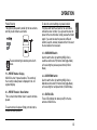
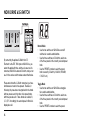
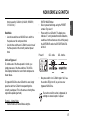
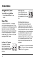
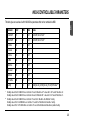
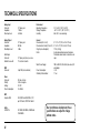
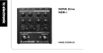
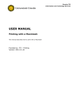
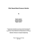
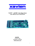
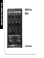
NOVA Drive
NDR-1
USER’S MANUAL
TABLE OF CONTENTS
Table of Contents . . . . . . . . . . . . . . . . . . . . . . . . . . . .3
Introduction . . . . . . . . . . . . . . . . . . . . . . . . . . . . . . . .4
Features . . . . . . . . . . . . . . . . . . . . . . . . . . . . . . . . . . .4
SETUP EXAMPLES
NOVA Drive
NOVA Drive
NOVA Drive
NOVA Drive
& Amp . . . . . . . . . . . . . . . . . . . . . . . . . .6
& G-System . . . . . . . . . . . . . . . . . . . . . .7
& G-Switch . . . . . . . . . . . . . . . . . . . . . . .8
in a MIDI Setup . . . . . . . . . . . . . . . . . . .9
OPERATION
MISCELLANEOUS
EN
INTRODUCTION
Setting the MIDI Channel of NOVA Drive . . . . . . . .18
Bypass Modes . . . . . . . . . . . . . . . . . . . . . . . . . . . . .18
Preset and Banks . . . . . . . . . . . . . . . . . . . . . . . . . . .19
NOVA Drive and G-System . . . . . . . . . . . . . . . . . . .21
NOVA Drive in a MIDI Setup . . . . . . . . . . . . . . . . . .22
MIDI Controllable Parameters . . . . . . . . . . . . . . . . .23
APPENDIX
Technical Specifications . . . . . . . . . . . . . . . . . . . . . .24
Additional Information . . . . . . . . . . . . . . . . . . . . . . .25
Overview . . . . . . . . . . . . . . . . . . . . . . . . . . . . . . . . .10
Connections . . . . . . . . . . . . . . . . . . . . . . . . . . . . . . .11
Switches and Knobs . . . . . . . . . . . . . . . . . . . . . . . . .11
NOVA Drive and G-Switch . . . . . . . . . . . . . . . . . . . .16
TC Electronic, Sindalsvej 34, DK-8240 Risskov – [email protected]
English Version
Manual revision 1.0 – SW – V 1.0
Prod. No: E60510711
3
INTRODUCTION
Introduction
Features
Guitarists everywhere – start your engines, because
your tone is about to take a new turn! Introducing
NOVA Drive, TC Electronic’s new dual engine, digitally
controllable, true bypass overdrive/distortion pedal,
featuring the awesome analogue drive circuit ported
from the acclaimed TC NOVA System.
Programmable All-analog Drive Circuit
Most guitar players know that analog circuits sound far
superior to digital ones – but the control options that
the digital domain brings are just too convenient to
ignore. NOVA Drive brings you the best of both worlds.
NOVA Drive brings you the great sounding analog
circuits from NOVA System, with all the digital control
that modern guitarists demand. The result: a classic
“old-school” sound that will send shivers down your
spine and paint a wide grin on your face at every riff,
lick and face-melter, along with digital control options
that enable you to integrate NOVA Drive into your setup and tailor the sound with total precision, giving you
more control, more confidence, and ultimately a better
performance. Finally, you have a platform to create,
store and recall all the distorted and overdriven sounds
you could ever need: NOVA Drive.
4
True Bypass
The true bypass design of NOVA Drive makes sure the
pedal won’t mess with your tone when you don’t want
it to. You can also select a high-quality buffered
bypass.
Extensive Routing Options
The extensive routing options of NOVA Drive allow for
a wide tonal palette – and a chance to let your aural
imagination run wild! Route the guitar signal through
the engines in any desired order. And even when the
results should be unexpected, they will always sound
great and enhance your music.
INTRODUCTION
EN
Programmable Control
From stomp box to bank mode to full MIDI control:
NOVA Drive ensures that you can program, store and
recall your favorite sounds quickly and without effort.
Integration with G-System
Connect NOVA Drive with G-System and get real-time
control of NOVA Drive’s parameters directly from
G-System.
5
SETUP EXAMPLE: NOVA DRIVE & AMP
This is a basic setup with a NOVA Drive
and a combo.
• Connect your guitar to NOVA Drive’s
input.
• Connect NOVA Drive’s output to the
guitar amp’s input.
• Set the routing and the switch mode.
• Adjust levels.
Read on to explore other configurations and
their advantages.
6
SETUP EXAMPLE: NOVA DRIVE & G-SYSTEM
EN
Combine NOVA Drive with a TC Electronic GSystem. The seamless integration of both units
provides you with new sonic possibilities.
• Start by making all connections according to the
illustration.
Please note that this setup requires an optional
MIDI split cable from TC Electronic.
• NOVA Drive appears in G-System’s menu.
You can now change NOVA Drive’s parameters
directly from G-System.
• Press G-System’s EDIT button and use the PAGE
encoder to select NOVA Drive parameters.
• When you store a preset on a G-System connected
to a NOVA Drive, the current NOVA Drive settings
are automatically stored as well.
NOVA Drive presets and settings are always
stored in NOVA Drive.
For further instructions on setting up G-System, please refer to the GSystem manual.
7
SETUP EXAMPLE: NOVA DRIVE & G-SWITCH
Expanding NOVA Drive with a G-Switch
By connecting the optional G-Switch from TC
Electronic to the EXT. SW. input on NOVA Drive,
you extend the pedal with three switches.
•
Use a TRS/TRS (stereo-jack) cable to connect
G-Switch to NOVA Drive’s EXT. SW. input.
As soon as it is connected, NOVA Drive detects GSwitch, and you can use it in the various switch
modes as described in the chapter “NOVA Drive
and G-Switch”.
Example:
With G-Switch connected and Bank Mode active,
you can select banks A to F using the UP/DOWN
switches on NOVA Drive. You can then choose
one of the three presets in that bank using GSwitch.
8
SETUP EXAMPLE: NOVA DRIVE IN A MIDI SETUP
EN
This is a simple MIDI setup, showing how NOVA
Drive perfectly integrates in setups where a MIDI
pedal is used as main controller. An expression
pedal is connected to the MIDI pedal and can be
used to control NOVA Drive’s various parameters.
9
OVERVIEW
10
Connections
Switches and Knobs
1 - Power
NOVA Drive requires 12V DC / 300 mA. Use the power
supply provided in the product box or a power supply
with identical specifications.
6 – OVERDRIVE Knob
This knob controls the amount of overdrive for the
overdrive section.
2 - Input
1/4" mono jack connector for signal input.
3 - Output
1/4" mono jack connector for signal output.
4 - MIDI
MIDI in/out on a single 5-pin DIN jack for external
control, e.g. from TC’s G-System.
5 - External Switch
For extended control using G-Switch by TC Electronic.
Please read the manual chapter “NOVA Drive & GSwitch” for further information.
EN
OPERATION
7 – LEVEL Knob
Use this knob to control the level of NOVA Drive’s
overdrive section.
8 – TONE Knob
Use this knob to shape the overdrive section’s tone.
Turn the TONE knob to the left for a darker sound and
to the right for a brighter sound.
9 – MIX Knob
With this knob, you can set a mix between the clean
signal and the processed (“driven”) signal. When set
correctly, this will sound as if you played over both a
clean amp and a drive amp simultaneously – a trick
often used in studio recordings for more punch and
transparency. We find it works best with single-coil
pickups for blues/rock.
11
OPERATION
10 – DISTORTION Knob
This knob controls the amount of distortion applied in
the distortion section of NOVA Drive.
11 – LEVEL Knob
Use this knob to control the level of NOVA Drive’s
distortion section.
12 – TREBLE Knob
This knob controls the high-end frequencies for the
distortion section. Turn it clockwise to increase treble
and counterclockwise to reduce it.
13 – BASS Knob
This knob controls the low-end frequencies for the
distortion section. Turn it clockwise to increase bass
and counterclockwise to reduce.
14 – >< LED Arrows
NOVA Drive is 100% analog, but the sound circuits are
digitally controlled. When you switch to a new preset,
the recalled values are most likely not the same as the
values represented by the current knob positions.
12
As soon as you start turning a knob, one of the “><”
arrow LEDs will indicate which way this knob should be
turned to locate the position corresponding to the
current value. The closer you are to the correct
position, the faster the arrow LEDs will blink.
When the knob is in the position that matches the
stored value, both arrow LEDs will be lit for a short
while.
15/16 – SWITCH MODE Button and LEDs
The two big foot switches on NOVA Drive can operate
in three different modes. Press the SWITCH MODE
button to alternate between these modes. The LEDs to
the left of the button indicate whether you are in
Normal, Toggle or Bank Mode.
Normal Mode
In this mode, the two sections of NOVA Drive operate
like two completely separate pedals that are connected
according to the selected routing. Please refer to the
section “ROUTING Mode Button and LEDs” on page
14 for further information on routings.
Press the OVERDRIVE and DISTORTION switches to
OPERATION
Toggle Mode
This is the mode to select if you know that you don’t
want to use both sections of NOVA Drive at the same
time. It allows you to toggle between the two sections
(overdrive and distortion) by tapping the OVERDRIVE
or the DISTORTION switch.
Example:
• You start with NOVA Drive in Bypass Mode.
• Press the DISTORTION switch to activate
distortion.
• Press the OVERDRIVE switch. The distortion
effect is switched off, and the overdrive effect is
activated.
• To bypass NOVA Drive completely, press the
switch corresponding to the currently active effect.
Bank Mode (with no G-Switch connected)
In Bank Mode, you can use NOVA Drive’s PRESET
encoder to select one of 9 banks (A to I), with each
bank holing two presets. In this mode, you use the
OVERDRIVE and DISTORTION switches to switch
between presets 1 and 2 within each bank.
EN
turn the respective section on or off.
Yes, both sections can be active at the same time! This
is excellent if you e.g. use a medium distortion setting
for rhythm parts and – on top of that – want to kick in
the overdrive section to drive the distortion input even
further for sparkling leads.
Example:
• Select bank “A” using the PRESET encoder.
• Press the OVERDRIVE switch. You’ll see that the
display shows “A1”, meaning: Bank A, Preset #1
has been selected.
• Now press the DISTORTION switch. The display
will show “A2” for Bank A, Preset #2.
• To bypass NOVA Drive completely, press the
switch representing the currently selected preset –
in this example, switch #2 (the DISTORTION
switch).
• The display now shows ”A” – indicating that you
are still in bank A, but no preset is selected.
Manual Mode
Manual Mode is a 100% “What you see is what you
13
OPERATION
get” mode (WYSIWYG). In this mode, NOVA Drive can
be used just like two independent pedals, and the
positions of all knobs always represent the respective
values.
To access Manual Mode:
• Select Normal or Toggle Mode (as described on
the previous page).
• Turn the PRESET encoder counter-clockwise until
the display shows:
Manual Mode is a WYSIWYG mode – but of
course, you can still store the current settings in
any of the 18 preset locations following the
standard store procedure: Press and hold the
PRESET encoder to enter Store Mode, select a
preset location and press the encoder once
more to finalize the store procedure (see also
“20 – PRESET Encoder / Store Button” on the
following page).
14
17/18 – ROUTING Mode Button and LEDs
NOVA Drive allows you to choose between three
different signal routings. A routing defines how the
signal runs through the unit. To switch between
routings, press the ROUTING switch.
Serial Routing (a):
The signal is going through the overdrive section first
and then to the distortion section. This is ideal if you
e.g. use the overdrive section to push the distortion
section (as many guitar players do with a boost pedal).
Serial Routing (b):
The signal is going through the distortion section first
and then to the overdrive section.
Parallel Routing:
The signal is processed in parallel by the two sections,
and they do not influence each other.
The selected routing is stored as part of each
preset.
19 – PRESET Number Display
NOVA Drive has 18 preset locations. The number of
the currently recalled preset is displayed in the 2x7segment display.
20 – PRESET Encoder / Store Button
This is a two-function button: Use it to select and store
presets.
To store the current settings at a preset location:
First press and hold the encoder for two seconds to
activate the store function. If you just want to store the
preset at the current location, simply release the button
again. If you want to store the preset at a different
location, keep the encoder pressed and turn it to select
the new location, then release it.
21 – OVERDRIVE Switch
Use this switch either for switching NOVA Drive’s
overdrive section on/off (in Normal and Toggle Mode)
or for selecting the previous preset bank (in Bank
Mode).
22 – DISTORTION Switch
Use this switch either for switching NOVA Drive’s
distortion section on/off (in Normal and Toggle Mode)
or for selecting the next preset bank (in Bank Mode).
23 – STATUS LEDs
These LEDs indicate the status (on/off) for the two
sections of NOVA Drive.
To select and recall a preset: Simply turn the knob to
browse and select presets.
15
EN
OPERATION
NOVA DRIVE & G-SWITCH
By connecting the optional G-Switch from TC
Electronic to the EXT. SW. input on NOVA Drive, you
extend the pedal with three switches. As soon as it is
connected, NOVA Drive detects G-Switch, and you can
use it in the various switch modes as described below.
Please note that with a G-Switch connected, you have
simultaneous access to three presets. Therefore, in
this setup, the presets are not organized in nine banks
with two presets each, but rather in six preset banks
with three presets each. These banks are called A, B,
C, D, E, F. Accordingly, the second preset in Bank A is
displayed as A2.
16
Normal Mode
• Use the two switches on NOVA Drive as on/off
switches for overdrive and distortion.
• Use the three switches on G-Switch to select one
of the three presets in the currently selected preset
bank.
• Use the PRESET encoder to select the preset
bank covered by G-Switch (A1/A2/A3; B1/B2/B3;
C1/C2/C3 etc.)
Toggle Mode
• Use the two switches on NOVA Drive as toggles
for overdrive and distortion.
• Use the three switches on G-Switch to select one
of the three presets in the currently selected preset
bank.
• Use the PRESET encoder to select the preset
bank covered by G-Switch (A1/A2/A3; B1/B2/B3;
C1/C2/C3 etc.)
Bank Mode
• Use the two switches on NOVA Drive to switch to
the previous or the next preset bank.
• Use the three switches on G-Switch to select one of
the three presets in the currently selected preset
bank.
•
•
SWITCH MODE button.
Select a preset bank/range using the PRESET
encoder. E.g. select 1.
Press switch 2 on G-Switch. The display now
indicates “2”, and ( provided that either distortion,
overdrive or both sections are active in this preset)
the OVERDRIVE and/or the DISTORTION LEDs
will be lit.
Preset #
OD - active
OD - inactive
Active or Bypassed
To activate one of the three presets in a bank, you
simply press one of the three switches. The NOVA
Drive display indicates the current bank and preset as
shown above.
•
To bypass NOVA Drive when G-Switch is used, simply
press the switch on G-Switch corresponding to the
currently used preset. This is the same as having three
regular drive pedals (per bank).
Now press switch 2 on G-Switch again. You’ll see
the section LED(s) turn off, as you have now
bypassed NOVA Drive.
Even when an effect section is bypassed, its
settings are stored as part of a preset.
Example – Normal Mode:
• Set NOVA Drive to Normal Mode using the
17
EN
NOVA DRIVE & G-SWITCH
MISCELLANEOUS
Setting the MIDI Channel
To set the MIDI channel on NOVA Drive:
• Press and hold the MODE switch for three
seconds.
Bypass Modes
As explained earlier, NOVA Drive is a true analog
design effect with digital parameter control. This allows
for selecting between two different bypass modes: Hard
Bypass Mode (“true bypass“) and Buffered Bypass
Mode. To select between these modes, press and hold
the ROUTING Mode button for three seconds. Once
the display shows “Hb” or “bb”, you can set the bypass
mode using the PRESET encoder.
Hard Bypass (Hb) – True Bypass
In the sought-after True Bypass
Mode, the input signal is going
directly to the output when in Bypass
Mode.This is the default setting for
NOVA Drive.
18
Buffered Bypass (bb)
In Buffered Bypass Mode, NOVA
Drive can drive long cables placed
after the pedal perfectly with no signal
loss.
Which Bypass Mode should you use?
Many sound aficionados discuss this topic with
religious fervor, and there is no definite answer. True
bypass equals removing the pedal from the board, so
in theory, this would be the natural choice, ensuring the
best signal quality. However, if no other component on
you pedal board buffers the signal and you use long
cables after the pedal board, you may experience a
significant loss of signal. This is even more likely when
you are using passive single coil pick-ups. The best
advice is to try out both bypass modes and let your
ears decide.
Depending on the equipment connected to NOVA
Drive, you may hear a click when switching NOVA
Drive in/out in True Bypass Mode.
PRESETS & BANKS
NO G-SWITCH
EN
All in all, NOVA Drive holds 18 presets. Depending on which switch mode you have selected and whether
NOVA Drive is used in conjunction with a G-Switch or G-System, these 18 presets are organized and
controlled in the following way.
SW 1
SW 2
ENCODER
NORMAL MODE
OVERDRIVE
On/Off
DISTORTION
On/Off
PRESET SELECT
1-18
TOGGLE MODE
Toggle to OVERDRIVE
or bypass
Toggle to DISTORTION
or bypass
PRESET SELECT
1-18
BANK MODE
Preset
Preset
BANK SELECT
9 banks of two presets,
labeled A to I
1
3
17
Bank A
Bank B
Bank I
2
4
18
Bank A
Bank B
Bank I
19
WITH G-SWITCH
PRESETS & BANKS
20
SW 1
SW 2
ENCODER
G-SWITCH
NORMAL
MODE
OVERDRIVE
On/Off
DISTORTION
On/Off
PRESET RANGE
1-3, 4-6, 7-9, etc.
PRESET SELECT
1-3, 4-6, 7-9, etc.
TOGGLE
MODE
Toggle to
OVERDRIVE
Toggle to
DIST
PRESET RANGE
1-3, 4-6, 7-9, etc.
PRESET SELECT
1-3, 4-6, 7-9, etc.
BANK
MODE
BANK DOWN
6 banks of three
presets available.
A-F
BANK UP
6 banks of three
presets available.
A-F
BANK SELECT
6 banks of three
A to F
PRESET SELECT
1-3, 4-6, 7-9, etc.
NOVA DRIVE & G-SYSTEM
To access NOVA Drive’s parameters from G-System:
• Press G-System’s EDIT button and turn the PAGE
encoder to select between the various NOVA Drive
parameter pages.
Example:
With the two units connected by means of the MIDI split
cable, you can edit the parameters either by using the
knobs and buttons on NOVA Drive pedal itself or by
using the PAGE and A, B, C encoders on G-System.
EN
NOVA Drive integrates perfectly with a TC
Electronic G-System.
First of all you should make the connections according
to the illustration on page 7 of this manual. Please note
that this setup requires an optional MIDI split cable
from TC Electronic.
As soon as the MIDI split-cable is plugged in, NOVA
Drive appears in G-System as an integrated effect, and
all its parameters can be adjusted just as any other set
of effect parameters in G-System.
Please note that even when you control NOVA
Drive from G-System, presets and settings are
always stored in NOVA Drive itself.
Connecting an expression pedal to G-System allows
you to control various NOVA Drive effect parameters in
real-time. The following NOVA Drive parameters can be
assigned for external control via G-System:
• Overdrive Amount
• Overdrive Level
• Distortion Amount
• Distortion Level
A typical way of using NOVA Drive with GSystem would be letting your G-System presets
handle whether NOVA Drive is engaged or not.
Also, you can have G-System recall a specific
NOVA Drive preset during preset changes – thereby
reducing the time required to get the desired sound in a
live situation.
It is worth noticing that when the pedal is placed on the
floor next to G-System, you can still use the two
switches on NOVA Drive to activate or deactivate the
drive and distortion sections.
21
NOVA DRIVE IN A MIDI SETUP
NOVA Drive integrates perfectly in a MIDI system.
Presets can be changed via MIDI program changes,
and certain parameters can be controlled in real-time
via MIDI CC’s.
For basic information of MIDI, please browse reference
sites on the Internet such as www.wikipedia.org
Provided your MIDI pedal can send MIDI CC and MIDI
Prg. Change messages, you have a number of
interesting options for “remote-controlling” NOVA Drive.
Here are some ideas:
• Mount NOVA Drive in a rack (see illustration) and
use two MIDI CC switches on your board for
switching OVERDRIVE and DISTORTION on and
off.
• Select NOVA Drive presets by sending program
change messages from your MIDI board to NOVA
Drive.
• Use an expression pedal to control e.g. the amount
of overdrive in real-time.
MIDI Channel
Per default, NOVA Drive sends and receives MIDI
messages on MIDI channel 2.
To change the MIDI channel:
• Press and hold the SWITCH MODE button for
three seconds.
• Turn the PRESET encoder until the desired MIDI
channel is shown in the display.
• Release the SWITCH MODE button.
22
MIDI-CONTROLLABLE PARAMETERS
*
**
Parameter
CC#
Min
Max
Notes
OD On/Off
21
0
127
0-63=Off, 64-127=On *
Dist On/Off
22
0
127
0-63=Off, 64-127=On *
OD Drive
23
0
127
OD Level
24
0
127
OD Tone
25
0
127
OD Mix
26
0
127
Dist Drive
27
0
127
Dist Level
28
0
127
Dist Bass
29
0
127
Dist Treble
30
0
127
Routing
31
0
127
Sending
Sending
Sending
Sending
Sending
values
values
values
values
values
EN
This table gives an overview of which NOVA Drive parameters that can be controlled via MIDI.
[0;42]=O->D, [43;84]=D->O, [85;127]=Parallel **
0 to 63 to NOVA Drive on controller 21 selects “Overdrive off” - values 64 to 127 selects “Overdrive on”.
0 to 63 to NOVA Drive on controller 22 selects “Distortion off” - values 64 to 127 selects “Distortion on”.
0 to 42 to NOVA Drive on controller 31 selects the “Overdrive into Distortion” routing.
43 to 84 to NOVA Drive on controller 31 selects the “Distortion into Overdrive” routing.
85 to 127 to NOVA Drive on controller 31 selects the Distortion and Overdrive in parallel routing.
23
TECHNICAL SPECIFICATIONS
Analog Input
Connector:
Impedance:
Max. Input Level:
1/4" phone jack
1 Mohm
6.25 dBu
Analog Output
Connector:
Impedance:
Max. Output Level:
1/4" phone jack
40 Ohm
8 dBu
Switch Input
Connector:
Suitable for use with:
1/4" phone jack (stereo) w. sense
TC electronic G-switch
Environment
Operating Temperature:
Storage Temperature:
Humidity:
General
Dimensions (W x H x D):
Dimensions incl. knobs (W x H x D):
Weight (excl. wall adapter):
Finish:
Mains Power Supply:
MIDI
Connector:
5-pin DIN (in/out combined)
Power
Connector:
Polarity:
Voltage:
Power Consumption:
DC-jack, ø6.4mm
Center is negative
12V DC
Ca. 380mA
EMC
Complies With:
Safety
Certified To:
24
Power Consumption:
Warranty Parts and labor:
32° F to 122° F (0° C to 50° C)
-22° F to 167° F (-30° C to 70° C)
Max. 90 % non-condensing
5" x 1.6" x 5" (127,5 x 41.4 x 131 mm)
5" x 2.2" x 5" (127,5 x 56.5 x 131 mm)
1.76 lb. (0.8 kg)
Acrylic and anodized aluminum front panel.
Plated and coated chassis. Coated steel endcaps
100 to 240 VAC, 50 to 60 Hz (auto-select) AC
wall adapter
<5W
1 Year
EN 55103-1 and EN 55103-2, FCC
part 15 Class B, CISPR 22 Class B
IEC 60065, EN 60065, UL60065 and
CSA E60065
Due to continuous development, these
specifications are subject to change
without notice.
ADDITIONAL INFORMATION
EN
Should this manual leave any of your questions unanswered, please use the TC
Support service, accessed via our website www.tcelectronic.com. Over a period
of time, we will collect the most frequently asked questions and update the
manual accordingly. Manual updates are available for download on our website in
PDF format.
We would also like to draw your attention to TC Electronics Youtube channel: www.youtube.com/tcelectronic, where
we continuously add instructional and promotional videos on TC Electronic products.
25