1
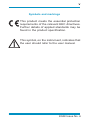
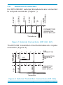
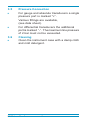
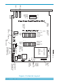
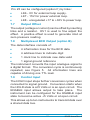
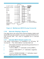
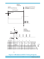
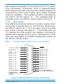
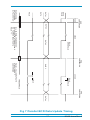
i
Druck DPI 260 Series
Digital Pressure Indicator
User Manual
K048
© Druck Limited 1995
This document is the property of Druck Limited and may not be
copied or otherwise reproduced, communicated in any way to third
parties, nor stored in any Data Processing System without the
express written authorisation of Druck Limited.
K048 Issue No. 6
ii
K048 Issue No. 6
iii
Contents
Section
1
2
3
Page
Introduction ................................................. 1
Specification ................................................ 2
Installation ................................................... 3
Panel Cut-out ................................................................. 3
Power Supply ................................................................ 3
D.C. Power Option ........................................................ 4
Electrical connection ..................................................... 5
Pressure connection ..................................................... 6
Cleaning ......................................................................... 6
4
Operation ...................................................... 7
5
Calibration .................................................... 7
Zero ................................................................................ 7
Span ............................................................................... 7
6
Setting-up ..................................................... 9
Coarse zero adjustment ................................................ 9
Coarse span adjustment ............................................... 9
Display over-range setting .......................................... 10
Linearity ....................................................................... 10
Decimal point position ................................................. 10
Bridge supply ............................................................... 11
DPI 262 Pre-amplifier .................................................. 11
Remote power supply sense ....................................... 11
7
Options ....................................................... 12
12 V d.c.power supply ................................................. 12
28 V d.c. power supply ................................................ 12
Analogue Output ......................................................... 12
Buffered Output ................................................... 12
Voltage Output ..................................................... 12
Current Output ..................................................... 12
Output Offset ....................................................... 12
Multiplexed BCD output .............................................. 13
Control Input ................................................................ 13
Remote Displays ......................................................... 14
Parallel BCD output ..................................................... 14
Hold Input .................................................................... 16
8
Fault Finding .............................................. 20
K048 Issue No. 6
iv
Safety
The manufacturer has designed this equipment to be
safe when operated using the procedures detailed in
this manual. The user must not use this equipment for
any other purpose than that stated. Do not apply
values greater than the maximum value stated.
This manual contains operating and safety instructions
which must be followed to ensure the safe operation
and to maintain the equipment in a safe condition. The
safety instructions are either warnings or cautions
issued to protect the user and the equipment from
injury or damage. Use qualified* personnel and good
engineering practice for all procedures in this manual.
*A qualified person must have attended a product
training course given by the manufacturer or appointed
agent and successfully completed the training course
on this equipment.
K048 Issue No. 6
v
Symbols and markings
This product meets the essential protection
requirements of the relevant EEC directives.
Further details of applied standards may be
found in the product specification.
This symbol, on the instrument, indicates that
the user should refer to the user manual.
K048 Issue No. 6
vi
Abbreviations
The following abbreviations are used in this manual.
Note:
Abbreviations are the same in the singular and the plural.
ac
alternating current
BCD
binary coded decimal
°C
degrees Celsius
dc
direct current
DIN
Deutsche Industrie Norm
EOC
end of conversion
FS
full-scale
FSD
full-scale deflection
HBC
high breaking current
Hz
Hertz
LK
link
mA
milli Ampere
max
maximum
min
minimum/minute
mm
millimetre
MΩ
mega Ohm
MSB
most significant bit
mV
millivolt
-ve
negative
Ω
Ohm
PCB
printed circuit board
+ve
positive
rms
root mean square
RV
potentiometer (variable resistor)
sec
second
SW
switch
TTL
transistor/transistor logic
V
Volt
VA
Volt Ampere
K048 Issue No. 6
1
Introduction
The Druck DPI 260 Series of instruments are generalpurpose pressure indicators that measure and display
pressure in specific pressure units with accuracies of
±0.1% FS or ±0.04% FS. The pressure sensor can be
an internally or externally fitted transducer or an
externally fitted transmitter.
Internal switches allow for 10 to 200 mV FSD input,
zero adjustment of ±19999 and decimal point selection.
The transducer excitation voltage of either -5 V or -10 V
can be selected by links on the bridge supply circuit
with a maximum load of 350 Ω. The transmitter supply
is also selected by links to an unregulated +20 Volts
(17.5 to 30 Volts) with a maximum current of 20 mA.
Linearization for square law is incorporated via the
supply. An over-range warning can be set to any
pressure.
A range of plug-in, retrofit digital and analogue output
options are available. The power supply can be 120 or
240 V a.c. (selected by link) or an option of 28 V d.c.
or 12 V d.c.
1
K048 Issue No. 6
2
Specification
Electrical safety
................... meets EN61010-1 as applicable
Power supply
................................................... 110 or 240 V
................................................... 50 to 400 Hz
............................................ 3 VA (maximum)
Electromagnetic compatibility
...................... meets EN50081-1 (emissions)
........................ meets EN50082-1 (immunity)
Operating temperature range .................
Combined non-linearity,
repeatability
°0 to 50°C
hysteresis
and
DPI 260 ±0.1% F.S., ±0.5% TEB ............ (to 60 bar)
DPI 261 ±0.04% F.S., ±0.005%/°C/TC ....... (to 35 bar)
DPI 262 ±0.1% F.S. ................................. (to 700 bar)
See data sheet for full details
K048 Issue No. 6
2
3
Installation
3.1
Panel Cutout
To fit the unit in a panel requires a mounted DIN
standard 92 x 45 mm cut-out. Locate the instrument in
the panel and secure with the case fixings from the
front panel screws.
3.2
Power Supply
WARNING
Voltages in excess of 30 V (RMS) a.c. or 50 V d.c.
can, in certain circumstances, be lethal. Care must
be taken when working on live, exposed
conductors.
CAUTION:
Identify the operating Voltage before connecting
the instrument.
AC powered instruments have black 3-core cables
that must be connected:
Brown
Blue
Green/Yellow
-
Live
Neutral
Earth
WARNING
Disconnect the power supply before removing the
instrument covers, live Voltages are present.
3
K048 Issue No. 6
An internal link selects a nominal 120 or 240 V a.c. the
operating limits are:
200-260 V a.c. 50-400Hz (Link P6/P7)
100-130 V a.c. 50-400Hz (Link P4/P7,P5/P6)
Electrical safety
To comply with electrical safety standards, the label
showing the operating Voltage MUST be changed
when the Voltage setting is changed.
An internal 500 mA 20 mm fuse is fitted in the live
circuit.
3.3
DC Power Option
DC powered instruments have white 2-core cables
that must be connected:
Brown
Blue
The operating limits are:
+12V or +28V
0V
10 - 14V d.c. at 300 mA (G option)
20 - 32V d.c. at 150 mA (H option)
An internal 500 mA 20 mm fuse is fitted in the positive
circuit.
Fuse replacement
Only replace the internal fuse (a.c. or d.c.) with a
ceramic HBC, F type fuse.
K048 Issue No. 6
4
3.4
Electrical Connection
1
2
3
4
SENSE
(OPTIONAL)
0V
SCREEN
- SUPPLY
- SIGNAL
+ SUPPLY
+ SIGNAL
For DPI 260/261 external transducers are connected
to a 6-pole connector (Figure 1).
5
6
CONNECTOR
GREENPAR
RM12 BPG-6P
Transducer
Figure 1 External Connections (DPI 260, 261)
The DPI 262 transmitter circuit terminates at a 6-pole
connector (Figure 2).
6
1
3
PCB
CONNECTOR
TRANSMITTER
INTERFACE
PCB
0va
2
BLUE
5
100Ω
⊗
1
RED
3
⊗
4
5
SCREEN
⊗
2
SIGNAL
(20 V)
SUPPLY
4
6
CONNECTOR
GREENPAR
RM12 BPG-6P
Transmitter
Figure 2 External Transmitter Connections (DPI 262)
5
K048 Issue No. 6
3.5
Pressure Connection
!
For gauge and absolute transducers a single
pressure port is marked "+".
Various fittings are available,
(see data sheet).
!
For differential transducers the additional
port is marked “-”. The maximum line pressure
of 2 bar must not be exceeded.
3.6
Cleaning
!
Clean the instrument case with a damp cloth
and mild detergent.
K048 Issue No. 6
6
4
Operation
The display shows the pressure applied to the sensor
(transducer or transmitter) in the units of pressure
measurement shown on the front panel. The zero
pressure setting can adjusted to increase or decrease
the reading. If the pressure reading exceeds the
preset maximum value (setting from 1999 to 19999)
the display shows a flashing 0000.
5
Calibration
Routine calibration adjustments should be made at
periods of 6 months, this period may be changed
depending on the frequency of use. Use an accurate
pressure standard to apply pressure and, if necessary,
adjust the instrument. Allow a warm-up time of
approximately 1 hour.
5.1
Zero
The zero adjustment is made using the 20-turn
potentiometer accessed through the front panel. For
gauge instruments make sure no pressure is applied.
For absolute instruments, apply a vacuum to the
transducer before adjustment.
To prevent
unauthorised adjustments fit a sealing label over the
potentiometer access on the front panel.
5.2
Span
The span adjustment for the full-scale pressure value
is made using the 20-turn span potentiometer accessed
through the front panel. Connect the pressure standard
to the instrument and adjust to the full-scale value. To
prevent unauthorised adjustments fit a sealing label
over the potentiometer access on the front panel.
7
K048 Issue No. 6
OFF
DIGITAL
OPTION
NO OPTION
LINK LK1
RV3
R3
SET
ZERO
SWZ
LK4 (5V)
+
PRESS TO
OPEN
SET
OVER-RANGE
P5 P6 P7 P8
OR
120V a.c.
LK2
L
N
E
240V a.c.
TRANSFORMER
IC1
RV2
R1
R4
6 5 4 3 2 1
12V DC - DC
CONVERTER
REPLACED
BY R2
FOR DPI 262
LK7 LK6 LK3
(20V)(10V)
SENSE
SUPPLY SELECT
(LK7 FOR DPI 262)
500 mA
20mm
FUSE
POWER
SUPPLY
LEAD
EARTH/
GROUND
TRANSDUCER
OR
TRANSMITTER
PCB (DPI 262)
Figure 3 Internal Layout
ANALOGUE
OPTION
SET
SPAN
SWS
-
ON
DECIMAL
POINT
SELECT
SWD
RV6
RV7
LK5
PRESS TO
OPEN
SET
LINEARITY
R2
8
K048 Issue No. 6
ZERO
SPAN
LK8
X10 GAIN
SELECT
SET
SUPPLY
RV5
PRESS TO
CLOSE
5 6 7 8
1 2 3 4
PRESS TO
CLOSE
1 2 3 4 5 6 7 8
RV4
6 5 4 3 2 1
6
Setting-up (Figure 3)
The DPI 260 Series of instruments can be configured
for other applications including zero and span settings.
6.1
Coarse Zero Adjustment
If a zero display is required for applied pressure other
than zero pressure an offset of ±19999 can be selected
by using the set zero switches SWZ on the PCB. Apply
the required pressure for zero and when stable select
open all the SWZ switches. If the pressure reading is
positive close switch 1, if negative close switch 2.
Close, in turn, switches 3 to 8 open the switch if the
reading overshoots zero. Using the zero calibration
procedure adjust the reading to read exactly zero.
The suppression of 4mA in the DPI 262 instrument is
achieved by this method by closing switches 1 to 7.
Using the zero calibration procedure, adjust the reading
to exactly zero.
6.2
Coarse Span Adjustment
The instrument can be set to read a "full-scale" reading
value up to 19999 for a transducer input of the range
10 to 200mV. Set the zero adjustment first, then using
the span set switches SWS set the required full-scale
value. Close all the SWS switches and apply the
required full-scale pressure.
If the reading is too high, remove link LK8. Open, in
turn, the switches 1 to 8, close a switch again if the
reading over-shoots the required reading. Using the
routine span procedure, adjust the reading to the exact
full-scale value.
9
K048 Issue No. 6
6.3
Display Over-Range Setting
The over-range condition (flashing 0000) can be set to
occur at any reading in the range 1999 to 19999. To
avoid this setting conflicting with the span setting, turn
potentiometer RV3 fully anti-clockwise (20 turns). Apply
the required over-range pressure or temporarily close
switches on SWZ. Adjust the potentiometer RV3
clockwise until the display flashes. Reduce the pressure
or reset the switches on SWZ.
6.4
Linearity
RV4 controls feedback between the amplified
transducer signal and the bridge excitation supply and
affects the correction for square law non-linearity.
Removing LK5 stops linearization feedback.
The following procedure only applies to transducers
where zero pressure equates to zero nominal output
from the transducer.
Note:
For other applications refer to Druck.
!
Remove LK5, carry out a zero and span
calibration.
!
Apply half-scale pressure and note the error.
!
Apply full-scale pressure and insert LK5.
!
Adjust potentiometer RV4 until the reading
equals full-scale plus 4 times the error
(e.g., if the midpoint is 3 counts low then adjust
the reading to [full-scale - 12 counts]).
6.5
Decimal Point Selection
SWD is used to select the position of the displayed
decimal point
K048 Issue No. 6
10
6.6
Bridge Supply
The supply is nominally -10V at zero pressure or -5V
if LK4 is inserted. Potentiometer RV5 adjusts the
voltage ±5%. In the DPI 262 instrument LK6 is
removed and LK7 inserted, this changes the supply to
an unregulated +20V (17.5 to 30V) for loop power.
6.7
DPI 262 Pre-amplifier
IC1 and the matched resistors R1, R2, R3 and R4
provide a high-accuracy, differential pre-amplifier with
a gain of 50 for transducers. Resistor R3 is replaced
by R2 creating a single-ended, unity gain amplifier. A
small plug-in PCB in the transducer connector contains
a 100Ω sense resistor which is connected between
SIGNAL+ and 0V. This provides a signal of 0.4 to 2V
for 4 to 20mA. The 0.4V is adjusted by SWZ (see
coarse zero adjustment) the span is adjusted by SWS
(see coarse span adjustment).
6.8
Remote Power Supply Sense
By removing LK3 the sensing circuit for the bridge
supply can be remotely connected via the transducer
external connector pin 6. The sense input impedance
is 20kΩ.
11
K048 Issue No. 6
7
OPTIONS
7.1
12V D.C. Power Supply (option G)
The a.c. power supply circuit is replaced by a DC to DC
convertor that generates ±20V, the 12V supply is
regulated providing a +5V supply. To identify the
option a white supply cable is fitted.
7.2
28V D.C. Power Supply (option H)
The a.c. power supply circuit is replaced by a DC to DC
convertor that generates ±28V, the 28V supply is
regulated providing a +5V supply. To identify the
option a white supply cable is fitted.
7.3
Analogue Output
This option is normally installed at manufacture but
can be retro-fitted by Druck or by the user. A plug-in
PCB assembly can be configured to produce, via a 25way connector (Figures 4 and 6) one of the following:
7.4
Buffered Output (option C)
A unity gain buffer produces the instrument reading as
a voltage with minimum errors (19999 = 2V).
7.5
Voltage Output (option D)
This amplifies the display voltage to an output voltage
10V max.
7.6
Current Output (option E and F)
The plug-in PCB can be configured so that Pin 13 and
Pin 25 on the 25-way connector (Figure 4 or 6) sinks
current (option E). The sink current depends on the
output voltage established by the buffered or Voltage
output options (maximum 16 mA or 80 mA
respectively).
K048 Issue No. 6
12
Pin 25 can be configured (option F) by links:
!
LK6 - 0V for external loop supply.
!
LK7 - 15V for power external loop.
!
LK8 - unregulated +17 to +30V to power loop.
7.7
Output Offset
The output (voltage or current) can be offset by inserting
links and a resistor. RV1 is used to fine adjust the
offset. A positive offset is used to generate 4mA at
zero pressure reading.
7.8
Multiplexed BCD Output (option B)
The data interface consists of:
!
4 information lines for the BCD data
!
4 address lines to indicate digit
!
1 clock line to indicate new data valid
!
1 signal ground reference
The instrument converts the input analogue signal to
a digital format. The conversion cycle is continuously
repeated, see Figure 5. All information lines are
capable of driving one TTL load.
7.9
Control Input
The HOLD input stops further conversion cycles when
connected to signal ground. Conversion starts when
the HOLD state is at 5 Volts or is an open circuit. The
ENABLE input allows output to take place. The
instrument can be configured for the ENABLE input
state to become active +5 Volts or at open circuit.
This allows up to ten instruments to transmit data over
a shared data bus.
13
K048 Issue No. 6
0 VOLT LOGIC
EOC/DATA CLOCK
BCD1
BCD4
1
2
3
4
5
D1
6
D3
SPARE
7
8
SPARE
SPARE
SPARE
9
10
11
SPARE
SPARE
12
13
ANALOGUE
SIGNAL 4 - 20 mA
(SINK)
14
ENABLE
15
HOLD
16
BCD2
17
BCD8
18
D2
19
D4
20
SPARE
21
SPARE
22
SPARE
23
SPARE
24
SPARE
25
0V ANALOGUE/
4 - 20 mA (POWER)
Figure 4 Multiplexed BCD 25-way Connector
7.10
Remote Displays (figure 5)
The digit lines can select the remote display digits and
the BCD lines decoded to a seven-segment drive form.
The Druck DPI 110 unit is supplied as a remote
display.
7.11
Parallel BCD Output (option A)
The BCD information is available on 25-way “D”
connector. The information is presented as:
!
!
4 decades of 4 bits (representing values 8,4,2,1
in positive logic).
1 bit for MSD (`1' indicates active MSD ).
!
1 bit for POLARITY (`1' indicates negative
value).
!
1 bit for OVER RANGE (`1' indicates input
signal greater than 19999).
K048 Issue No. 6
14
DATA
CLOCK
HOLD
(ON CONVERSION)
X
NEXT CONVERSION
STARTS
(IF FREE RUNNING)
0.45S approx
300nS MIN
X
X
DATA
CLOCK
EXPANDED
20mS
4µS
approx
1.0mS
OUTPUT
1
2
3
4
5
BCD8
BCD4
BCD2
BCD1
DIGIT 1
DIGIT 2
DIGIT 3
DIGIT 4
1
1
THOUSANDS
HUNDREDS
TENS
UNITS
approx
0
1
0
0
0
0
1
0
0
0
0
1
0=+
0=-
MSD
0
0
0
0
1
0
0
0
1
1
0=+
0=-
ETC
0
0
0
0
X
Figure 5 Multiplexed BCD Timing diagram
15
K048 Issue No. 6
Each signal is capable of driving up to five TTL loads.
The information conversion cycle is approximately
400 milliseconds with a short period, approximately 10
milliseconds at the end of each cycle, when the data
output is updated. This update period is indicated by
the DATA VALID signal `0'. The updated data is
available when the DATA VALID signal returns to `1'.
7.12
Hold Input
The HOLD input stops further conversion cycles when
connected to signal ground. Conversion starts when
the HOLD state is at `1' or is an open circuit; the data
flow is free running, see figure 7. The HOLD input (at
`0') latches the data output, the display continues to
update each measurement cycle. A short pulse (>300
nano second) starts an update indicated by a pulse of
the DATA VALID output.
Note:
A single trigger mode is not recommended.
0 VOLT LOGIC
POLARITY
BCD1 x 100
BCD4 x 100
1
1
2
3
4
5
BCD1 x 10
BCD4 x 101
2
BCD1 x 10
BCD4 x 102
BCD1 x 103
3
BCD4 x 10
MSD1 x 104
OVER-RANGE
6
7
8
9
10
11
12
13
ANALOGUE
SIGNAL 4 - 20 mA
(SINK)
14
HOLD
15
DATA VALID
16
BCD2 x 100
17
BCD8 x 100
18
BCD2 x 101
19
BCD8 x 101
20
BCD2 x 10
21
BCD8 x 102
22
BCD2 x 103
23
BCD8 x 10
24
MSD2 x 104
25
0V ANALOGUE/
4 - 20 mA (POWER)
2
3
Figure 6 Parallel BCD 25-way Connector
K048 Issue No. 6
16
DATA
VALID
DATA
DATA 1
HOLD
400mS
DATA 3
END
CONVERSION
HOLD
400mS
DV = 0
WHEN HOLD
>300nS
TRIGGER/HOLD
HOLD = ‘1’ ALLOWS UPDATE
AT NEXT END OF
CONVERSION
END
CONVERSION
DATA 4
K048 Issue No. 6
17
END
CONVERSION
10 mS
DV = 0
WHEN HOLD
DATA 2
Dv = AS HOLD CHANGED TO ‘0’
DATA UPDATED AT END OF 400mS
NO FURTHER UPDATE UNTIL
HOLD = ‘1’
DATA 2
FREE RUNNING
EACH 400mS
DATA UPDATED
Dv PULSES TO‘0’
Fig 7 Parallel BCD Data Update Timing
8
FAULT FINDING
In the event of a malfunction instruments can be
returned to the Druck Service Department or Druck
agent for rectification.
The following fault finding procedures in Table 1 must
be carried out by qualified* personnel using good
engineering practise. Make sure power supply is
disconnected from the instrument before accessing
internal components.
* see the safety page (i)
Table 1 Fault Finding
FAULT
ACTION/CAUSE
No display
1. CHECK power supply switched on.
2. CHECK power supply fuse.
3. CHECK power cable.
4. CHECK internal 500mA fuse.
5. REPLACE power supply module.
6. REPLACE display PCB failure.
Flashing display
OVER-RANGE CONDITION
1. REDUCE applied pressure.
2. CHANGE over-range setting.
Unstable display 1. CHECK applied pressure.
2. CHECK stability of power supply.
3. CHECK for electromagnetic
interference near the instrument and
power supply.
4. CHECK cable on external sensors.
5. CALIBRATE instrument.
6. REPLACE pressure sensor.
K048 Issue No. 6
18