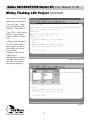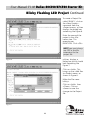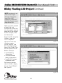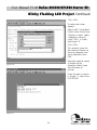
1
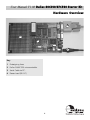
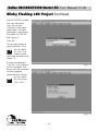
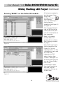
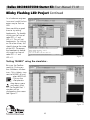
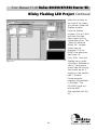
USER
GUIDE
(Version 1.00)
Dallas 80C320/87C520 Starter Kit User Manual V1.00
Copyright Information
Equinox guarantees that its products will be
free from defects of material and
workmanship under normal use and service,
and these products will perform to current
specifications in accordance with, and subject
to, the Company’s standard warranty which is
detailed in Equinox’s Purchase Order
Acknowledgment.
or copied only in accordance with the terms of
the agreement.
It is against the law to copy the software on any
medium except as specifically allowed in the
license or non-disclosure agreement.
The purchaser may make one copy of the
software for backup purposes. No part of this
manual may be reproduced or transmitted in any
form or by any means, electronic, mechanical,
including photocopying, recording, or
information retrieval systems, for any purpose
other than for the purchaser’s personal use,
without written permission.
Equinox reserves the right to change
specifications detailed in this document
without notice and does not represent a
commitment on the part of the manufacturer.
The software described in this document is
furnished under license agreement or
non-disclosure agreement and may be used
© 1999 Copyright Equinox Technologies UK Limited. All rights reserved.
Dallas Semiconductors™ is a trademark of the Dallas Semiconductor Corporation
Microsoft, MS-DOS, Windows™ and Windows 95™ Windows NT™ are registered
trademarks of the Microsoft Corporation
IBM, PC and PS/2 are registered trademarks of International Business Machines
Corporation
Every effort was made to ensure accuracy in this manual and to give appropriate credit to
persons, companies and trademarks referenced herein.
i
User Manual V1.00 Dallas 80C320/87C520 Starter Kit
Electromagnetic Compatibility (EMC) Compliance
The Dallas 87C520/80C320 Programmer is a CE Approved Product. It is designed only for
use in a development environment only. This means that the user must ensure that there is
no possibility of damage from electrostatic discharge (ESD). Since the devices and equipment
to which this product is likely to be connected may well themselves be susceptible to ESD,
this should not pose any difficulty.
For example, if you are handling microcontrollers and EEPROMS etc. then you will already be
used to appropriate precautions, such as the use of anti-static mats, wrist straps and so on.
You should treat your Dallas 87C520/80C320 with the same care as you would these type of
device. Always ensure that you are not yourself carrying a static charge before handling the
product. Wearing an earthed anti-static wrist strap is recommended.
Equinox have taken great care in designing this product to be compliant with the European
EMC directive. When using the equipment be sure to follow the instructions provided.
Although RF emissions are within prescribed limits, care should be taken if you are using the
product near to sensitive apparatus. If you experience any difficulty please refer to Equinox
technical support.
ESD Points to remember
●
Work in a static-free environment.
●
Wear an earthed wrist strap when handling either the programmer
and/or any programmable device.
Please Note:
This equipment is NOT designed to be used in a production environment.
ii
Dallas 80C320/87C520 Starter Kit User Manual V1.00
Technical Support
It is often the case that users experience problems when installing or using a product for the first time.
Due to the low-cost nature of this product, Equinox are unable to answer technical support questions
about this product or its use by telephone.
If you have a technical support problem, please consult the following list for help:
1 This manual
2 Troubleshooting Guide (see page 17)
3 On-line help
The Keil PK51-2K IDE (µVision and dScope) feature on-line context sensitive help. Press <F1> for
help at any time.
Simply press <F1> on any error message and the possible causes of the error should be listed. This
help system is updated on a regular basis. Please see software update details for information on
keeping up-to-date with software revisions.
4 Internet Web Site
i Equinox Web site
The microcontroller support page can be found at: www.equinox-tech.com or
ii Keil On-Line Technical Support Database
Keil operate a ‘Technical Support Database’ on their website which provides up-to-date answers
to real technical support questions: www.keil.com
5 E-mail
Please e-mail any technical support questions about this product to: [email protected]
Equinox will try our best to answer your questions about this product as quickly as possible.
However, we can not promise an immediate reply. Please consult our web site for new software
updates as the problem that you are enquiring about may have already been fixed in a new version.
6 Fax
Please fax any technical support questions about this product to: +44 (0) 1204 535555
Equinox will try our best to answer your questions about this product as quickly as possible.
However, we can not promise an immediate reply. Please consult our web site for new software
updates as the problem that you are enquiring about may have already been fixed in a new version.
iii
User Manual V1.00 Dallas 80C320/87C520 Starter Kit
Contacts
Equinox Technologies UK Limited
3 Atlas House, St Georges Square, Bolton, England BL1 2HB
Telephone Sales ....................... : +44 (0) 1204 529000
Fax .............................................. : +44 (0) 1204 535555
E-mail ......................................... : [email protected]
Web site .................................... : www.equinox-tech.com
For technical support on this product please e-mail us at:
[email protected]
iv
Dallas 80C320/87C520 Starter Kit User Manual V1.00
About Dallas Microcontrollers
Dallas Semiconductors™ High speed microcontroller is an 8051-compatable device that
provides improved performance and power consumption. The fundamental innovation of the
high speed microcontroller is the use of four clocks per instruction as compared to twelve
with the original 8051, This results in an up to three times improvement in performance.
Recommended Reading
1 Keil Reference Manual Set
Set of manuals for the PK51 (C51, A51 & Utilities)
Order Code: PK51-MANUALS
2 Equinox Guide to C and the 8051
Order Code: BK-C51-1
3 Dallas 520 Microcontroller Data Book
(Included with kit)
v
User Manual V1.00 Dallas 80C320/87C520 Starter Kit
Contents
Introduction.........................................................................1
Device Support....................................................................2
System Specifications .........................................................3
Hardware Overview ...........................................................4
Software Overview.............................................................5
Hardware Installation Instructions ....................................6
‘Blinky’ Flashing LED Project ..............................................7
Troubleshooting Guide .....................................................17
Upgrades/Associated Products ........................................18
Dallas 80C320/87C520 Starter Kit User Manual V1.00
Introduction
This CE compliant starter kit provides a
suite of development tools for the DALLAS
DS87C520 and DS80C320 microcontrollers.
These microcontrollers support the standard
8051 instruction set but provides the speed
of a 16 bit processor. They feature 2
full-duplex hardware serial ports and four
8-bit I/O ports. Also included in the kit is
the powerful KEIL PK51-2K Integrated
Development Environment (IDE) featuring
an Editor, Macro assembler, C Compiler,
Linker, software simulator and Hex creator.
DALLAS DS80C320/DS87C520
PROGRAMMER HIGHLIGHTS
• State-of-the-art Device Programmer
• Supports
Dallas 80C320 microcontroller
Dallas 87C520 microcontroller
• Connects to spare PC Serial Port
• Straightforward hardware/software
installation
This toolset allows up to 2K of program
code to be written for a Dallas 320/520
derivative. The development board allows
this code to be downloaded in ‘real-time’
from the IDE into external memory and run
‘live’ on the board. It is possible to set
breakpoints and single-step the user
program using this system.
• Code can be downloaded from PC to
Target System in Real Time
• Break points can be set
• Can be single stepped
NOTE a copy of “BLINKY” is now supplied
on floppy disk with the kit if you don’t feel
like keying it in for yourself.
1
User Manual V1.00 Dallas 80C320/87C520 Starter Kit
Device Support
DALLAS Microcontrollers
DS80C320
High speed microcontroller with the following features:
• Standard 8051 Instruction Set
• Four 8-bit I/O ports
• Three 16-bit timer/counters
• 256 bytes scratchpad RAM
• Multiplexed address/data bus
• Addresses 64KB ROM and 64KB RAM
DS87C520
High speed microcontroller with the following features:
• Standard 8051 Instruction Set
• 4 8-bit I/O Ports
• 3 16-bit timer/counters
• 256 bytes scratchpad RAM
• 16KB on-chip EPROM (OTP)
• 1KB extra on-chip RAM for MOVX
ROMSIZE™ Feature
• Selects effective on-chip ROM size from 0 to 16KB
• Allows access to entire external memory map
• Dynamically adjustable by software
• Useful as boot block for external FLASH
Please Note: The PK51-2K Toolset is also capable of generating up to 2K of code which
can be placed in internal code memory of the microcontroller. A separate ‘parallel’
programmer and the use of the 87C520 EPROM/OTP device would be required. (Not
supplied with the system).
2
Dallas 80C320/87C520 Starter Kit User Manual V1.00
System Specifications
DALLAS STARTER KIT
SPECIFICATIONS
Programmer Size
: 170 x 100 x 15mm
Shipped Weight
: Approx 0.50kg
MINIMUM PC REQUIREMENTS
The minimum hardware and software
requirements to ensure that the
programmer operates correctly are as
follows:
Shipped Size (Box) : 315 x 205 x 115mm
PC Connection
: Serial Port 9-pin
female D Connector
or 25-pin adaptor
supplied
Power Supply
: 9V DC supplied
with kit. Lead centre
+VC
100% IBM compatible 386+
Windows 3.1 or higher
Minimum 4MB RAM
Minimum 1MB free hard disk space
Spare PC serial port
KIT CONTENTS
• MCB251 Board
(8051 Monitor Module)
• Keil PK51-2K Software (2 Floppies)
• Serial Cable
• 9-25way adaptor
• Power Supply
• 1 Keil Evaluation Board Manual
• 1 Keil Evaluation Kit Manual
• 1 Dallas High-Speed Microcontroller
Data book
• 1 Dallas Data Book and CD-ROM
• Keil CD-ROM
• 1 Floppy containing ‘BLINKY’ project
• 1 User Guide
• 1 Registration Card
• 1 PK51 Product Overview
3
User Manual V1.00 Dallas 80C320/87C520 Starter Kit
Hardware Overview
3
1
2
4
Key
1
Prototyping Area
2
Dallas DS80C320 microcontroller
3
Serial Cable to P.C.
4
Power Lead (9V DC)
4
Dallas 80C320/87C520 Starter Kit User Manual V1.00
Software Overview
The KEIL PK52-2K software supplied with
this kit contains powerful development
tools to program test and debug DALLAS
microcontrollers.
Please consult the KEIL evaluation manual
supplied with this kit.
5
User Manual V1.00 Dallas 80C320/87C520 Starter Kit
Hardware Installation Instructions
OVERVIEW
The Dallas programmer connects to any spare PC serial (COM) port. If you only have one
serial port and this is in use for eg. a modem, it may be possible to add another serial port to
your machine by inserting a new I/O card.
For further hardware installation help, please refer to the: Installation Troubleshooting
Guide.
Connect the programmer to the PC as follows:
1 Plug Dallas Development Module into spare PC serial port.
2 Apply power to the target board.
Dallas Development Module
Serial Cable
POWER
SUPPLY
UNIT
OFF
Users PC
(Not Supplied)
ON
Power Supply Unit (PSU)
6
Dallas 80C320/87C520 Starter Kit User Manual V1.00
Blinky Flashing LED Project
Introduction
Software Installation
In order to help you become familliar with
this product the following project guides
you through the installation of the Keil
PK51-2K software and the steps needed to
generate a working program.
With Windows loaded, insert PK51-2K disk
1 and from the RUN menu type a:\setup
click O.K. Follow the on-screen instructions.
Before re-starting the computer remove the
floppy disk. The Keil installation program
creates a ‘Program Group’ as shown in
Figure 2. The software should also be
installed on the ‘Start’ menu.
Blinky Example Program
The following simple program “BLINKY” is
an exercise you may use to test the kit and
verify that you can use the tools provided.
Figure 1 Connections.
Hardware Requirements
• DALLAS 87C320 starter kit.
• A PC with Windows 3.1, Windows
95 or Windows 98 with an available
RS-232 port.
• If the port has a 25 pin connector an
adapter is supplied with the kit.
Connect the board as shown in Fig 1.
Jumper Settings
As shown in Figure 1.
DIP Switch Settings
Set the DIP switch settings to:
1,3,5,6,7,8 & 9
ON
2,4 & 10
OFF
Figure 2
Start up
screen.
7
User Manual V1.00 Dallas 80C320/87C520 Starter Kit
Blinky Flashing LED Project Continued
Creating your first project
Start
Double Click on µVision-51
or select <Start><Program>
<Keil PK51-2KB><µVision-51>
Switch
OFF
LED
Delay (waste time)
for 10,000 counts
F
(<10,000)
When µVision starts, select the <NEW>
command from the
drop down File menu. µVision opens a new
test window in which you may create the
“BLINKY” program.
cntr
<10,000
P
Enter the “BLINKY” program as shown in
Figure 3b.
Switch
ON
LED
The LED Illuminates
NOTE to save you time the program is
a supplied on a floppy disk.
Delay (waste time)
for 10,000 counts
cntr
<10,000
F
Figure 3a. flowchart for program
P
// blinky.c led flasher
#include <reg320.h>
//Includes register declarations for the Dallas DS320/520 microcontrollers
sbit LED = P1^3;
//Assigns the label ‘LED’ to Port 1 bit 3
unsigned int cntr;
//counter variable
void main (void)
{
while(1)
{
LED = 1;
//Declares start of
for
{;}
//Start of
‘main’ function
‘while’ loop
(cntr=0; cntr<10000; cntr++)
//Delays for 10000 counts
LED = 0;
for
{;}
}
(cntr=0; cntr<10000; cntr++)
}
// End of
//Delays for 10000 counts
‘while’ loop ñ jumps to start of ‘while loop
// End of ‘main’ function
Figure 3b program text.
8
Dallas 80C320/87C520 Starter Kit User Manual V1.00
Blinky Flashing LED Project Continued
Your screen should look
something like Figure 4.
Click on <File>, <Save
as> and name the file
BLINKY.C see Figure 5.
Click <OK>. After saving
BLINKY.C you should
create a BLINKY Project
File.
A Project File contains a
list of all source files in
your project as well as
the options to use for
the compiler,
assembler, linker and
make facility.
Additionally the Project
Manager helps you to
compile, link and test
your target program.
Figure 4 entered text.
Figure 5
9
User Manual V1.00 Dallas 80C320/87C520 Starter Kit
Blinky Flashing LED Project Continued
To create a Project File
called ‘BLINKY’, click on
the <New Project>...
command from the
<Project menu>, µVision
displays the dialog box
something like Figure 6.
Enter the name of the
project in the <File
name> box. This
example uses
BLINKY.PRJ. Click <OK>.
NOTE you must always
use .PRJ as the file
extensions for the
project file.
µVision displays a
dialog box which should
look something like
Figure 7.
Figure 6
Click on <Add>. This
brings up the <Add file>
to <Project menu> as
shown in Figure 8.
Make the File name
blinky.c
Click on <Add> then
<Close>. Click on
<Save> to save the
changes to the Project
file.
Figure 7
10
Dallas 80C320/87C520 Starter Kit User Manual V1.00
Blinky Flashing LED Project Continued
NOTE to return at any
time to the Project
Manager dialog box
select the <Edit
Program> command
from the Project menu
drop down box.
When you have created
a Project file and
inserted the source files
into the project, you are
ready to set the options
for the compiler, linker
and other tools.
To set the C51 Compiler
Options, select the
<C51 Compiler>
command from the
<Options menu>
µVision displays the
C51 Compiler options.
Select the <Object Tab>.
Set the options for the
BLINKY example:
Figure 8
• Include debug
information
• Include extended
debug information
• Enable ANSI integer
promotion rules.
For Interrupt vectors
select Include in object,
Interval 8 and Offset 0.
See Figure 9.
Figure 9
11
User Manual V1.00 Dallas 80C320/87C520 Starter Kit
Blinky Flashing LED Project Continued
Click <OK>.
To select the Linker
options:
Select <BL51 Code Bank
Linker> from the µVision
<Options> menu. Select
<Segment> tab and
insert “30h” in Code.
See Figure 10.
Click <OK>.
This reserves space for
the interrupt vectors so
the user program now
starts execution from
30h.
Next you need to create
a dScope file by
selecting <New> from
the File menu of
µVision.
Figure 10
Enter the text as shown
in Figure 11. Save file as
DSCOPE.INI.
Figure 11
12
Dallas 80C320/87C520 Starter Kit User Manual V1.00
Blinky Flashing LED Project Continued
The DSCOPE.INI window
can now be closed.
From the µVision
<Options> drop down
menu select <dscope
Debugger>. Now enter
the name DSCOPE.INI.
See Figure 12.
Click OK.
You are now ready to
compile BLINKY. Click
on the <Build
all> icon. The
screen should
now look something like
Figure 13.
If errors are detected
Click OK, a list of errors
will be displayed. The
errors must be corrected
and the program
recompiled by clicking
on the <build
all> icon again.
Figure 12
Click <OK>.
Figure 13
13
User Manual V1.00 Dallas 80C320/87C520 Starter Kit
Blinky Flashing LED Project Continued
Running ‘BLINKY’ on the Dallas 320 module...
At last you are ready to
test the project. From
the µVision
window click on
the <Debug>
icon. You should get a
display looking
something like Figure 14
or Figure 15.
You must set the baud
rate to 19200 and the
comm port to the port
you are connected to on
your computer.
Note. If the debug
window does not
appear click on <View>
then <Debug window>.
Try again.
Figure 14
You should now have a
display something like
Figure 15. Click on
<Configuration> on the
<Peripherals> menu and
set <Use serial
interrupt> to ‘ON’,
select <Apply> then
<Close>. See Figure 16.
To display the dialog bar
turn on <Show Dialog
bar> in the
<Commands> menu.
You should be able to
start and stop the
program by clicking on
Go and Stop.
Figure 15
14
Dallas 80C320/87C520 Starter Kit User Manual V1.00
Blinky Flashing LED Project Continued
As a hardware engineer
I am sure I could find an
easier way to flash an
LED!
Now would be a good
time to try setting
breakpoints. Try double
clicking on the lines of
code LED = 1 and
LED = 0. This will set
breakpoints. Try clicking
on Go a few times, this
should change the state
of the LED. To remove
the breakpoints double
click again on lines of
code LED = 1 and
LED = 0.
Figure 16
Testing ‘BLINKY’ using the simulator...
Bring up the Toolbox
menu by Clicking on
the <Toolbox> window
icon. Click <Select> icon
next to MON51.dll and
select 80320.dll.
Click on the
<Peripherals>
drop down menu
and select <Port
1>. The Parallel Port 1
window will be
displayed on the screen.
See Figure 17.
Figure 17
15
User Manual V1.00 Dallas 80C320/87C520 Starter Kit
Blinky Flashing LED Project Continued
Move this window to
the right of the screen
to a position under the
Toolbox window.
From the Toolbox
window, Click on <File>
and from the drop
down menu click on
<Load object file>. The
“Select an absolute
Object file” window
should now be
displayed. Click on
BLINKY (no extension).
See Figure 18.
Click <OK>. From the
Toolbox menu, select
<Go Main> followed by
<Run>. The program
should now be running.
You should see bit 3
toggling in the parallel
port 1 window.
Figure 18
Further example
programs are available
in the book “The
EQUINOX Guide to C
and the 8051”
(Not supplied with this
kit)
16
Dallas 80C320/87C520 Starter Kit User Manual V1.00
Troubleshooting Guide
1 Installation problems
• Does your PC meet the minimum PC requirements of this product?
• Do you have spare PC serial port?
• Have you connected the serial cable from the PC COM port to the Dallas programmer?
• Have you selected the correct COM port?
• Is the serial port already in use by another application?
• Have you applied power to the Dallas programmer?
17
User Manual V1.00 Dallas 80C320/87C520 Starter Kit
Upgrades/Associated Products
1 A software upgrade is available from Equinox Technologies to upgrade from the PK51-2K
to the PK51-8K (More information about the 8K package can be found in the PK51 user
manual)
Order Code: ................................................................................................ PK51-8K-UPG
2 The Micro-PRO-Plus is available from Equinox Technologies, which allows downloading of
the user program code into internal code memory.
Order Code: .................................................................................................... MPW-PLUS
18
Equinox Technologies UK Limited reserves the right to change any information contained within
this manual without prior notice. E&OE
Terms and product names contained in this document may be trademarks of others.