1
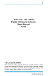
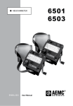
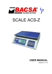
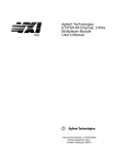
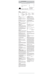
Ohmmeter Replacement Guide
(From 3540 to RM3544)
1. Measurement
2. Functionality
3. External Control (EXT I/O)
4. Commands
Please prepare copies of the user manuals for the old and new instruments and review the applicable sections of each.
If you do not have access to these manuals, they can be downloaded in PDF format from your myHIOKI website.
http://www.hioki.com/
Please note that this guide may be revised or up dated without notice.
1. Measurement
(1) Range structure comparison
3540
Range
30mΩ
300mΩ
3Ω
30Ω
300Ω
3kΩ
30kΩ
RM3544
Display
range
30.00mΩ
300.0mΩ
3.000Ω
30.00Ω
300.0Ω
3.000kΩ
30.00kΩ
Measurement
current
100mA
100mA
1mA
1mA
1mA
10μA
10μA
Open
terminal
voltage
4.0V max
Range
30mΩ
300mΩ
3Ω
30Ω
300Ω
3kΩ
30kΩ
300kΩ
3MΩ
Display
range
35.000mΩ
350.00mΩ
3.5000Ω
35.000Ω
350.00Ω
3.5000kΩ
35.000kΩ
350.00kΩ
3.5000MΩ
Measurement
current
300mA
300mA
30mA
10mA
1mA
1mA
100μA
5μA
500nA
Open
terminal
voltage
5.5V max
The RM3544 has a five-digit display.
○ How to set the number of display digits
Menu [P.2/2] Setting screen (SETTING) → Measurement Setting screen (MEAS) → Number of measurement digits (Ω DIGITS)
(2) Temperature sensor
Use of the 9451 Temperature Sensor that came with the 3540 is not recommended. Doing so will cause completely different
temperature measured values (around 70°C) to be displayed.
Only use the optional, Hioki-specified Z2001 Temperature Sensor. Please note that the Z2001 is not a standard accessory of
the RM3544.
(3) Measurement leads
Use of 3540 measurement leads (9287-10, etc.) with the RM3544 is not recommended (and doing so will place the
performance of the instrument outside the accuracy guarantee). The leads that come with the RM3544 and optional
measurement leads (L2101, etc.) include a guard terminal in order to reduce the effects of external noise. Although there is
no difference in the leads’ center value (average value), use of the 3540 measurement leads with the new instrument will
make measurement more susceptible to the effects of noise, so their performance should be verified in the environment in
which they are to be used first.
If you plan to make your own measurement leads, refers to “10: Making Your Own Measurement Leads” in the RM3544 User
Manual.
1
Jan. 14, 2014
users_guide_RM3544_fr_3540-E1-41M
2. Functionality
(1) Hold function
The RM3544 incorporates an auto-hold function. Please note that the manner in which this function operates differs from the
3540’s hold function. If you have been using the 3540’s hold function in combination with its EXT I/O functionality, change the
RM3544’s trigger source to external trigger [EXT].
○ How to change the trigger source setting
Menu [P.2/2] Setting screen (SETTING) → EXT I/O Setting screen (I/O) → Set the trigger source (TRIG SOURCE) to
external trigger (EXT).
(2) Manual comparator
The RM3544 does not provide functionality that corresponds to the 3540’s manual comparator function (MANU signal).
(3) Comparator table
The RM3544’s panel load function corresponds to the 3540’s comparator table.
○ Panel data saved
Resistance measurement range, measurement speed, zero-adjustment, averaging, comparator, judgment tone, scaling,
temperature correction (TC), auto-hold
2
Jan. 14, 2014
users_guide_RM3544_fr_3540-E1-41M
3. External Control (EXT I/O)
The timing of some aspects of the RM3544’s operation differs from that of the 3540. Be sure to review the timing charts in the
RM3544’s User Manual.
(1) Switching between current sink (NPN) and current source (PNP)
The RM3544 allows you to switch between NPN and PNP operation. To control the instrument in the same way as the 3540,
set the NPN/PNP switch to NPN. The instrument ships with the switch in the NPN position. The EXT I/O mode cannot be
changed using commands.
Left: Current sink (NPN)
Right: Current source (PNP)
(2) Connector
The RM3544 connector is configured as follows:
8
7
TRIG, IN0
BCD_LOW
KEY_LOCK
LOAD1
LOAD3
(Reserved)
(Reserved)
ISO_5V
ISO_COM
ERR
19 18 17 16 15 14 13 12 11 10 9
6
5
4
3
2
1
37 36 35 34 33 32 31 30 29 28 27 26 25 24 23 22 21 20
0ADJ
(Reserved)
LOAD0
LOAD2
(Reserved)
(Reserved)
PRINT, IN1
ISO_COM
EOM
INDEX, BCD2-0, RNG_OUT0
3
IN
BCD2-2, RNG_OUT2
BCD3-0
BCD3-2
BCD4-0
BCD4-2
BCD5-0, BCD1-0
OUT1, BCD5-2, BCD1-2
Mating Connectors:
DC-37P-ULR (solder type) /
DCSP-JB37PR (pressure weld type)
Japan Aviation Electronics Industry Ltd.
HI, HILO
LO, BCD2-1, RNG_OUT1
BCD2-3, RNG_OUT3
BCD3-1
BCD3-3
BCD4-1
BCD4-3
OUT0, BCD5-1, BCD1-1
OUT2, BCD5-3, BCD1-3
Connector: (Instrument Side)
37-pin D-sub female with #4-40 screws
Jan. 14, 2014
users_guide_RM3544_fr_3540-E1-41M
(3) Signal table
Power
Description
Power
Ground/common
Input
Description
TRIG
(measurement start)
Manual mode
Output
3540
5V
GND
RM3544
ISO_5V
ISO_COM
3540
RM3544
TRIG
TRIG
MANU
-
Range setting
RANGE
-
Zero adjustment
Printer output
Table/panel
BCD low-order byte
output*
Key lock
General-purpose input
0ADJ
PRINT
COMP0 to 3
0ADJ
PRINT
LOAD0 to 4
-
Description
Comparator Hi
Comparator IN
Comparator Lo
Comparator HiLo
Measurement current
error
Measurement complete
Analog measurement
complete
Range data output
3540
Hi
IN
Lo
-
RM3544
HI
IN
LO
HILO
CCERR
ERR
EOC
EOM
-
INDEX
DPO to 2
BCD (digit 103) – bit 3
BCD (digit 103) – bit 2
RNG_OUT0 to 3
BCD5-3
BCD5-2
BCD_LOW
BCD (digit103) – bit 1
BCD5-1
KEY_LOCK
IN
BCD (digit103) – bit 0
BCD (digit102) – bit 3
BCD (digit102) – bit 2
BCD (digit 102) – bit 1
BCD (digit102) – bit 0
BCD (digit 101) – bit 3
BCD (digit 101) – bit 2
BCD output *
BCD (digit 101) – bit 1
BCD (digit101) – bit 0
BCD (digit 100) – bit 3
BCD (digit 100) – bit 2
BCD (digit 100) – bit 1
BCD (digit 100) – bit 0
General-purpose output
-
BCD5-0
BCD4-3
BCD4-2
BCD4-1
BCD4-0
BCD3-3
BCD3-2
BCD3-1
BCD3-0
BCD2-3
BCD2-2
BCD2-1
BCD2-0
BCD1-3
BCD1-2
BCD1-1
BCD1-0
OUT0 to 2
* BCDm-n: Outputs the nth bit of digit m. (BCD1-x is the lowermost digit, while BCDx-0 is the LSB.)
The 3540’s external connector (BCD, CCERR, and ECO signals) generates TTL output, but the RM3544 generates all opencollector output.
(4) BCD and DP (RNG_OUT) signals
When only using the uppermost four digits as with the 3540, use the instrument with the BCD_LOW signal set to off. To acquire
the first digit of the measured value and range information, it is necessary to control the BCD_LOW signal.
(5) Measurement range setting
The RM3544 does not have a range setting signal. Instead, you should save range information on each panel and then switch
ranges using the panel load function. (For example, PANEL1: 30 mΩ range, PANEL2: 300 mΩ range)
4
Jan. 14, 2014
users_guide_RM3544_fr_3540-E1-41M
(6) Acquiring judgment results
The RM3544 does not provide any functionality that corresponds to the 3540’s manual comparator function (MANU signal).
The judgment result and BCD signals are cleared at different times on the two instruments. As with the 3540’s EOC signal,
judgment results should be acquired while the RM3544’s EOM signal is on.
3540: Hold state timing chart
TRIG
ON
EOC
OFF
OFF
Judgement
ON
OFF
ON/OFF
result/BCD
ON/OFF
○ When the EOC signal turns on, the judgment result and BCD signals change.
RM3544: Timing chart when using the external trigger [EXT] setting
TRIG
EOM
Judgement
result/BCD
ON
OFF
OFF
ON
OFF
OFF
ON/OFF
OFF
○ When the TRIG signal turns on, the judgment result and BCD signals are cleared.
○ When the EOM signal turns on, the judgment result and BCD signals change
5
Jan. 14, 2014
users_guide_RM3544_fr_3540-E1-41M
4. Commands
Most 3540 commands can be used with the RM3544, but some must be changed due to differences in display resolution and
other aspects of instrument operation. Be sure to read over the following before using 3540 commands with the RM3544.
(1) Command correspondence chart
○ Set the number of measurement digits to 4 to accommodate the 3540.
○ If replacing 3540 commands with RM3544 commands, see the corresponding commands.
RM3544
Operation when using 3540 commands and associated operating
Command
precautions
RESET
Corresponding RM3544 command
This command changes the instrument to the settings listed below. It *RST
configures the instrument to reflect the 3540’s initial state. Please note
that the resulting reset operation differs from a normal reset.
*This command differs from RST as follows:
○ Number of measurement digits setting: 4 digits
○ Auto-range operation: On
○ Measurement range: 30 mΩ range
○ Number of measurement digits setting: 5 digits
○ Measurement speed: Slow
○ Trigger source: Internal trigger
○ Comparator: Off
○ Comparator mode: ABS
○ Comparator upper and lower limits: 0
○ Judgment tone (Hi, IN, Lo): Off
○ Temperature correction function (TC): Off
○ Zero-adjustment data: Off
○ Line frequency: Auto
RMES
○ This command configures the number of measurement digits setting to :FETCh?
reflect the 3540’s setting of 4 digits. The response will indicate the
In the response, digits that are not displayed due to
number of digits selected with the number of measurement digits
the number of measured digits setting are replaced
setting.
with the numeral 0.
○ If the measured value is negative, it will begin will a minus sign (-)
rather than a space.
Example: If the display indicates -20.00 mΩ, the response will be
-20.00E-03. If the display indicates -2.00 mΩ, the response will be
-2.00E-03.
○ If the comparator is set to REF%, the following formula is used as with
the 3540, yielding a value that differs from the display:
TMES
Absolute value = Measured value / Reference value × 100 [%]
This command can be used just as with the 3540.
TRG
This command produces the following operation, depending on the trigger ○ When acquiring the most recent measured value
:FETCh:TEMPerature?
:FETCh?
source setting:
○ When applying the trigger by command and
○ Internal trigger
acquiring the measured value
Returns the current measured value.
:READ?
○ External trigger
Applies the trigger and returns the measured value after measurement
completes.
The response will be the same as the RMES command.
EOC
This command can be used just as with the 3540.
Use the event status register.
ADJ
This command can be used just as with the 3540.
:ADJust?
For more information about the zero-adjustment range, see the User
Manual. If zero-adjustment results in a warning and then execution
completes, the response will be “OK.”
FUNC
The RM3544 does not provide this function, but the command will always
yield a response of “OK.”
6
Jan. 14, 2014
users_guide_RM3544_fr_3540-E1-41M
RM3544
Operation when using 3540 commands and associated operating
Command
precautions
RNG
This command makes the following setting depending on the data portion:
Corresponding RM3544 command
:SENSe:RESistance:RANGe
0:30mΩ range
1:300mΩ range
2:3Ω range
3:30Ω range
4:300Ω range
5:3kΩrange
6:30kΩrange
Calling the RNG command after the CHI or CLO command causes the
comparator setting value to be converted to a resistance value based on
the RNG command’s range.
SMP
This command makes the following setting depending on the data portion:
:SAMPle:RATE
0: Sets the measurement speed to slow.
1: Sets the measurement speed to fast.
HZ
This command can be used in the same manner as on the 3540. However, :SYSTem:LFRequency
the RM3544 provides an automatic frequency detection function, and it is
recommended to use that function.
HOLD
The RM3544’s trigger source setting provides functionality equivalent to the When inputting the trigger signal using EXT I/O
3540’s hold setting. This command makes the following setting depending :TRIGger:SOURce
When applying the trigger with a command
on the data portion:
:INITiate:CONTinuous
0: Internal trigger
1: External trigger
AUTO
This command can be used in the same manner as on the 3540. However, :SENSe:RESistance:RANGe:AUTO
specifying auto-range operation when the comparator function is on will
result in an execution error.
TC
This command can be used in the same manner as on the 3540.
:CALCulate:TCORrect:STATe
COMP
This command can be used in the same manner as on the 3540.
:CALCulate:LIMit:STATe
Turning on the comparator function during auto-range operation will cause
auto-range operation to be canceled.
CNO
This command is invalid and will result in a command error.
CMD
This command makes the following setting depending on the data portion:
: CALCulate:LIMit:MODE
0:ABS mode
1:REF% mode
It can be executed even when the comparator is off and will not result in an
execution error.
BUZ
This command makes the following setting depending on the data portion:
:CALCulate:LIMit:BEEPer
0: Turns all judgment tones off.
1: Turns the judgment tone for IN to off, for Hi and Lo to on, and for type 2
to 2 tones.
2: Turns the judgment tone for IN to on, for type 2 to 2 tones, and for Hi
and Lo to off.
CHI
This command converts the count value in the data portion to a resistance :CALCulate:LIMit:UPPer
value based on the current range and sets it. Calling the RNG command :CALCulate:LIMit:LOWer
after the CHI command converts the value to a resistance value based on
the RNG command’s range and sets it. It can be executed even when the
comparator is off and will not result in an execution error.
7
Jan. 14, 2014
users_guide_RM3544_fr_3540-E1-41M
RM3544
Operation when using 3540 commands and associated operating
Command
precautions
CLO
Corresponding RM3544 command
This command converts the count value in the data portion to a resistance :CALCulate:LIMit:REFerence
value based on the current range and sets it. Calling the RNG command :CALCulate:LIMit:PERCent
after the CLO command converts the value to a resistance value based on
the RNG command’s range and sets it. It can be executed even when the
comparator is off and will not result in an execution error.
CCC
This command is invalid and will result in a command error.
LOCK
This command can be used in the same manner as on the 3540.
:SYSTem:KLOCk
(2) Measured value format comparison chart
The plus sign for measured values has been replaced with the space character (ASCII code 20h).
Resistance measured values
Range
30.00 mΩ
300.0 mΩ
3.000 Ω
30.00 Ω
300.0 Ω
3.000 kΩ
30.00 kΩ
3540 (RMES command)
Current
Measured
OF
fault
values
+□□.□□E-03
OF
CC ERR
+□□□.□E-03
OF
CC ERR
+□.□□□E-00
OF
CC ERR
+□□.□□E-00
OF
CC ERR
+□□□.□E-00
OF
CC ERR
+□.□□□E+03
OF
CC ERR
+□□.□□E+03
OF
CC ERR
RM3544
Range
Measured values *
±OvrRng
BAD DATA
BAD DATA
BAD DATA
BAD DATA
BAD DATA
BAD DATA
BAD DATA
30.000 mΩ
300.00 mΩ
3.0000 Ω
30.000 Ω
300.00 Ω
3.0000 kΩ
30.000 kΩ
300.00 kΩ
3.0000 MΩ
±□□.□□□E-03
±□□□.□□E-03
±□.□□□□E+00
±□□.□□□E+00
±□□□.□□E+00
±□.□□□□E+03
±□□.□□□E+03
±□□□.□□E+03
±□.□□□□E+06
±10.000E+19
±100.00E+18
±1.0000E+20
±10.000E+19
±100.00E+18
±1.0000E+20
±10.000E+19
±100.00E+18
±1.0000E+20
Comparator REF% mode
3540 (RMES command)
Measured
OF
Current fault
values
□□□.□
OF
CC ERR
fault
+10.000E+29
+100.00E+28
+1.0000E+30
+10.000E+29
+100.00E+28
+1.0000E+30
+10.000E+29
+100.00E+28
+1.0000E+30
RM3544
TC error
Measured values
±OvrRng
BAD DATA
±□□□.□□E+00
±100.00E+18
Temperature measured values
3540 (TMES command)
Measured
OF
values
+□□.□
Measurement
TC error
Measurement
fault
+100.00E+28
RM3544
OF
8
Measured values
±OvrRng
±□□.□ E+00
±10. 0E+19
Measurement
fault
±10. 0E+20
Jan. 14, 2014
users_guide_RM3544_fr_3540-E1-41M
Note: Company names and Product names appearing in this catalog are trademarks or registered trademarks of various companies.
HIOKI (Shanghai) SALES & TRADING CO., LTD.:
TEL +86-21-63910090 FAX +86-21-63910360
http://www.hioki.cn / E-mail: [email protected]
DISTRIBUTED BY
HIOKI INDIA PRIVATE LIMITED:
TEL +91-124-6590210 FAX +91-124-6460113
HEADQUARTERS:
E-mail: [email protected]
81 Koizumi, Ueda, Nagano, 386-1192, Japan
TEL +81-268-28-0562 FAX +81-268-28-0568 HIOKI SINGAPORE PTE. LTD.:
http://www.hioki.com / E-mail: [email protected] TEL +65-6634-7677 FAX +65-6634-7477
E-mail: [email protected]
HIOKI USA CORPORATION:
HIOKI KOREA CO., LTD.:
TEL +1-609-409-9109 FAX +1-609-409-9108 TEL +82-42-936-1281 FAX +82-42-936-1284
http://www.hiokiusa.com / E-mail: [email protected] E-mail: [email protected]
All information correct as of Jan. 14, 2014. All specifications are subject to change without notice.
users_guide_RM3544_fr_3540-E1-41M
Printed in Japan