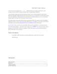
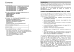
1
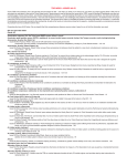
Harrison R&D
www.obdscan.net
Houston, TX
OBDScan Manual Version
March 22, 2005
Congratulations for choosing the Harrison R&D OBDScan. We have made every
attempt to insure your success with this product. Please take time to read
through these operating instructions and become familiar with the operating
procedure.
The OBDScan Tool, enables access to your vehicle’s diagnostic
information. Read and clear Diagnostic Trouble Codes from the vehicle’s
memory, turn off the “Check Engine” light, and read real-time sensor
measurements are just some of the features offered by the OBDScan Tool.
What is a Scan Tool?
In today’s cars the microcomputer is used extensively for engine control, antilock
brakes, air bag control, active suspension and many other applications.
Microcomputers communicate with the outside world through a ‘user interface’,
which could be a keyboard, mouse and CRT as on your home computer or a Scan
Tool in the case of the OBD-II computer. Imagine trying to communicate with
your home computer without a keyboard and CRT. Humans cannot
communicate directly with a computer so a ‘user interface’ is required. The Scan
Tool is the keyboard-CRT equivalent for your vehicle computer.
As mandated by U.S. law, the OBD-II Scan Tool has a single, standard interface
connector used to mate with the vehicle. This connector has been defined by the
standard SAE-J1962 and MUST be located within 1 meter of the steering wheel
and must not require any tools to access.
Using the Scan Tool
The Scan Tool provides access to the vehicle sensor readings, emission system
status and trouble codes. Many mechanics make use of a scan tool to assist in
diagnosing and repairing problems. Repair shops charge $80 or more to read the
Diagnostic Trouble Code one time. Purchasing a OBDScan can pay for it’s self in
as little as two uses! Even if you don’t do your own repair work, the knowledge
you gain from reading the trouble codes yourself can keep the repair shop honest
and demonstrate to the shop that they are not dealing with an uninformed
customer.
The OBDScan can clear the trouble code and turn off the Check Engine light after
the repair has been made.
Supported Vehicles:
The OBDScan will support all OBD-II compliant vehicles. This means all cars
and light truck sold in North America beginning with the 1996 model year.
1
Harrison R&D
www.obdscan.net
Houston, TX
There are a few known OBD-II problems on certain vehicles, the 2000 Nissan
Maxima and Altima, some 2000 Suzuki’s, 1996-1997 Hyundai and 1996-2000
Daewoo. We do not support the 1996-1999 Ford F-250/350 Diesel engine vehicles
at this time.
OBDScan for Windows Software
The OBDScan application is a fully Windows 95/98/ME/2000/XP compliant
program, written in Microsoft Visual Basic 6.0. To install OBDScan, follow
directions on the CD or download from the web site at
www.ghg.net/dharrison/software.htm. We recommend getting the latest
software from our web site. The install program will install the executable file
and all required DLL’s. In some instances you may receive a warning message,
if so it is usually safe to choose to ignore the warning.
Getting Started with OBDScan Version 3.XX
Before connecting the protocol converter, launch OBDScan by either double
clicking the icon or selecting it from the PROGRAMS menu. You should see the
screen shown in Fig1.
2
Harrison R&D
www.obdscan.net
Houston, TX
Figure 1. OBDScan Display Screen
Select the COM port or USB that will be used communication by clicking on the
Connection menu bar item as shown above. Select the desired COM port from
the drop down menu. If the selected port is not available or being used by
another program then you will get an error. A common source of this error is the
Palm HotSync program. The Windows operating system only allows one
program at a time to control any individual COM port, so be sure to quit any
other applications that may use the COM port to be used by OBDScan. Once you
have successfully selected a COM port, the “ECU Status” box will change from
red to yellow with the message “ECU Init”, meaning that it’s waiting on the
protocol converter to initialize the ECU. By completing this phase, you're ready
to go on to actual communication with a vehicle. Connecting to a Vehicle - Please
check to be sure that your vehicle is 1996 or newer and is compatible with the
interface type purchased. If you purchased the OBDScan-universal model then
3
Harrison R&D
www.obdscan.net
Houston, TX
all 1996-2002 cars and light duty trucks with will work. The CANScan will work
with 2003 and later vehicles with CAN bus. Cars between 2003 and 2007 model
year can be either CAN bus or the older OBD-II interface types, call or email us
to be sure you have the correct interface type if in question. Locate the OBD-II
connector, it’s required by U.S. law to be within 1 meter of the steering wheel.
It’s usually located under the dash, but if not there then check behind ashtrays
and in any console compartments. Be sure your computer is within cable reach
of the OBD-II connector. You can use up to 50ft of RS232 extender if required.
With the ignition off, plug in the OBD connecter on the protocol converter to the
mate in the vehicle. Start the vehicle engine and the ECU Status indicator will
change green when the ECU has been initialized. Once it’s green, select “Request
Diagnostic Trouble Codes” by clicking the mouse with the cursor over the
button. You should get a display in the vehicle status window like: MIL is OFF,
There are no trouble codes set. If your MIL light is ON and/or you have trouble
codes set, then your display should indicate so. You can find the definitions for
the SAE trouble codes on the Harrison R&D web site. As defined by SAE-2012,
diagnostic trouble codes (DTC) consist of a three digit numeric code preceded by
an alphanumeric designator. If the alphanumeric designator is ‘P0’ then the
trouble code is SAE defined, however if the alphanumeric designator is ‘P1’ then
the DTC is manufacturer defined and you will need a shop manual for the
vehicle to decode the DTC. For example, if a trouble code of P0150 was
displayed, then it is SAEcontrolled and would indicate a problem in the O2
sensor. If the DTC was P1298 then you would have to consult the shop manual
for an explanation. To clear any trouble codes and turn off the MIL, select the
function “Clear/Reset Diagnostic Trouble Codes”. This clears all trouble codes
and turns off the MIL. Now select “Request Current Power Train Diagnostic
Data”. You will see data appear in both the Vehicle Status Window and Vehicle
Data Window. The data appearing at this time is mostly optional and varies
from vehicle to vehicle. Any data appearing the Vehicle Data Window can be
selected for real time display by double clicking the item. For example, to see
throttle position move the cursor to the line in the Vehicle Data Window where
throttle position is displayed and click twice. A window will pop up like the one
shown in Fig. 2. This window will continuously display throttle position until
you press the Stop button on the Fast Data Display window. The Fast Data
Display provides a real troubleshooting benefit with the large characters for easy
viewing and rapid update rate for fast changing data and the new strip chart
recorder so that your data is available in graphic form. You can print data from
the main screen by selecting the Print button. OBDScan always uses the system
default printer.
4
Harrison R&D
www.obdscan.net
Houston, TX
Figure 2. Fast Data Display Window
Logging Data to Disk
It’s now possible to save selected data to disk using the data log screen. You get
to this screen by clicking the Data Log on the menu bar. A drop down menu will
appear with a single item, MultiView. You can only select the log function if you
have previously selected the ‘Request Current Powertrain Diagnostic Data’from
the startup window. The data log screen looks like figure 3.
5
Harrison R&D
www.obdscan.net
Houston, TX
Figure 3. Data Log Screen
To log data, you first select the numberso of items you wish to log in the bottom
box, 'Number of Parameters', then select the actual parameters that will be
logged by holding the mouse over the down arrow at the right side of the ‘Select
Up To Six Parameters to Record’ box. A drop down menu will pop down and
then you move the mouse to the selected parameter, as shown in figure 4. You
must make sure the value selected in the Number of Parameters box equals the
number of parameters you have actually selected.
After the parameters have been selected click ‘Start Log’ and you will be asked
for a file name to save the data in and then the data logging will begin. The four
Display boxes on the right side of the window will display the selected
parameters in real time while the data is being logged. To end the data log
operation, click the red ‘Stop Log’ button. The data is saved in a text format in
the file you selected.
Import a data lof file into Excel
Open Excel, select Data > Get External Data > Import Text File. Select the log file
using the File Open dialog box. When the log file loads, Excel will open a Text
Import Wizard. On the first window select Delimited then Next. The next
window will open. In the Delimiters box select 'Comma' then click Next. In the
6
Harrison R&D
www.obdscan.net
Houston, TX
next window, Step 3, click General in the Column Data Format as shown below.
Click Finish then OK on the next window which asks where to put the data, it
will go in the default location.
7
Harrison R&D
www.obdscan.net
Houston, TX
When the log file imports the Excel window should look similar to the figure
below. The column on the far right is a relitive time from the start of the log.
OBDScan Users Guide
Using OBDScan
A scan tool is one of the most important tools a mechanic can have today. With
virtually all engine control under the guidance of a computer the need for
visibility into the vehicle control system is absolute. OBDScan provides the data
required to diagnose and repair engine problems quickly and efficiently.
1. Connecting OBDScan to a vehicle
Be sure that the OBDScan software was installed from the disks supplied per the
instructions before proceeding. Locate the OBDII connector in the vehicle (The
connector must be located within one meter of the steering wheel and must not
require any tools to be revealed. Look under the dash and behind ashtrays) and
connect the mating OBDScan connector to it. It will look like the figure below:
8
Harrison R&D
www.obdscan.net
Houston, TX
Helpful link for finding the connector:
http://www.epa.gov/otaq/cert/dearmfr/vpcd9814.pdf
Next connect the RS-232 cable with the DB9 connector to the serial port of either
a laptop or desktop computer. You will need to know if the serial port you’re
using is COM1, 2 or 3. Consult your user manual for the computer to find out. If
more cable length is needed you can use a standard RS-232 extension cable which
has a 9 pin male on one end and a 9 pin female on the other, the extension cable
can be up to 50 feet if needed.
2. Operation
Run the OBDScan executable program. When the screen shown in figure 1
appears, click in the appropriate COM port to start. The ECU status indicator
should be yellow and say “ECU Init”. Now either start the vehicle or switch the
ignition to the ‘On’ position. The ECU status should turn green if the vehicle is
OBD-II and the correct COM port was selected. Allow 4-5 seconds for
communication to begin. Click on “Request Current Power train Diagnostic
Data” and a screen similar to Figure 1 should appear. NOTE: In some cars,
Chrysler, Mitsubishi, Volvo and KIA, the transmission controller will respond
before the engine controller and will only provide 2-3 engine parameters and test
results. If this is the case then click on “Change ECU” and retry “Request
Current Power train Diagnostic Data”. You should get most OBD-II mandated
test results and most of the data parameters shown in Table 1. The exact data will
vary from car to car. Next click on “Request Diagnostic Trouble Codes” and you
should normally get a message that indicates that the MIL is not on and there are
no trouble codes. If the MIL is on, then the message will indicate so and list the
trouble codes, which caused the MIL to illuminate. If trouble codes were present
and the problem has been fixed, you can click on “Clear/Reset Diagnostic
Trouble Codes” to clear trouble codes and turn off the MIL. Only use the clear
trouble codes function with the engine off and the ignition switch in the ‘on’
position.
3. What does the data mean?
9
Harrison R&D
www.obdscan.net
Houston, TX
The OBD II specification requires onboard diagnostic software that looks at
system efficiency, and system failures. The ECU does this with very
sophisticated software monitors, which are constantly evaluating the health of
the vehicle emissions system. To the professional or shadetree mechanic, it’s like
having an expert mechanic living under the hood.
As you use the scan tool to read test status and diagnostic data, you may find
some of the tests are complete and others not complete. A test which is not
complete does not necessarily indicate a problem, the ECU may be evaluating an
OBD trip or drive cycle. To complete an OBD trip the vehicle must reach at least
160 deg F., the conditions for the monitoring tests must be met, and the tests
completed to a pass/fail point. Remember, not all OBD-II vehicles support all
possible status and data items.
OBD Status Items:
A. Misfire Monitoring
The diagnostic monitor must determine if there is single or multiple cylinder
misfires. This test measures flywheel acceleration after firing each spark plug to
determine if there was a misfire or not. If misfires exceed 2% then an error
condition exists
B. Number Of Oxygen Sensors
Number of O2 sensors on the vehicle. Since OBD-II mandates two O2 sensors
per catalytic converter, the number should always be even.
C. Component Monitoring
A comprehensive test of the emissions related sensors and effectors to validate
their operation.
D. Catalytic Converter Monitor
A test to determine the efficiency of the catalytic converter. The OBD software
compares the O2 sensors pre and post catalytic converter. The post converter
sensor should show very little change in output voltage over time with respect to
the pre converter O2 sensor.
E. Heated Catalytic Converter Monitor
Measure the length of time it takes for the catalyst to begin operation after a cold
start. If the time exceed a manufacture set limit an error condition is set.
F. Evaporative System Monitor
Amount other things, will detect a missing or loose gas cap and leaks in the
unpressurized fuel system
G. Secondary Air System Monitor
Monitors the performance of the secondary air system by evaluating the catalytic
converter performance when the secondary air is engaged.
10
Harrison R&D
www.obdscan.net
Houston, TX
H. A/C Refrigerant Monitor
Monitors the pressure of the refrigerant
I. Oxygen Sensor Monitor
This test monitor the operation of the O2 sensor as the fuel/air mixture is
adjusted between rich and lean. The time needed to make the transition from rich
to lean cannot surpass 100ms on the pre-catalytic converter O2 sensor.
J. Oxygen Sensor Heater Monitor
This test monitors the length of time it takes for the O2 sensor to begin operation.
The turn-on time varies with the vehicle and O2 sensor and is set by the
manufacturer.
K. EGR Monitor
A change in MAP is used to determine the status of the EGR system. The EGR
valve will be forced open during closed throttle deceleration and a change in
MAP is used to determine proper operation.
L. Fuel Trim Monitor
Fuel trim monitoring looks at the average short- or long-term correction needed
to bring the air/fuel ratio into line. If these fuel trim values reach and stay at their
limits for a period of time, a malfunction is indicated.
M. Commanded Secondary Air Status
Indication of secondary air engaged or not.
Emissions Related Engine Data
The next set of data consists of mostly sensor data and two calculated values,
Calculated load and Short and Long Term Fuel Trim. The calculated load is a
relative number estimating engine load (torque) for the given RPM. The fuel
trim numbers represent the average short- or long-term correction needed to
bring the air/fuel ratio into stoichiometry. If these fuel trim values reach and stay
at their limits for a period of time, a malfunction is indicated. The ignition timing
is the value set by the ECU and does not include any mechanical advance,
however most of today’s engines are totally electronic and have no mechanical
advance.
Table 1. OBD Data Items:
A. Calculated Load
B. Coolant Temp.
C. Short and Long term Fuel Trim
D. Fuel Pressure
E. Intake Manifold Pressure
11
Harrison R&D
www.obdscan.net
Houston, TX
F. RPM
G. Vehicle Speed
H. Ignition Timing
J. Intake Air Temp
K. Air Flow
L. Throttle Position
M. Oxygen Sensor Voltage
The remainder of the data consists of the various sensor readings which will vary
from vehicle to vehicle.
Coolant Temp. - Represents the temperature of the engines coolant. Normally
about 180-190 Deg. F. on most cars
Fuel Pressure - Represents the regulated pressure on the fuel rail. This is a very
important value; the fuel/air ratio is determined by length of time the fuel
injector is pulsed on. If the fuel pressure is not constant, then the ECU cannot
maintain the correct fuel/air ratio, causing emissions or performance problems.
Intake Manifold Pressure - This sensor creates a signal that is proportional to the
average pressure in the intake manifold. The pressure should be low and fairly
steady at idle and light loads and will go higher as the load increases, up to
atmospheric pressure.
Intake Air Temp - Usually a resistive device (thermistor) which is placed in the
intake air stream, and provides a voltage proportional to temperature.
Air Flow - This sensor provides a voltage which is representative of the airflow
into the intake manifold. Most newer vehicles us a ‘hot wire anemometer” type
sensor for this measurement.
Throttle Position Sensor - This sensor generates a voltage proportional to
instantaneous throttle position (0-100%).
Oxygen Sensor Voltage - This sensor is much more complicated than the other
sensors and deserves a more detailed explanation. Basically, the O2 sensor
indicates the presence or absence of oxygen in the exhaust stream. The ECU, in
order to keep emissions low, adjusts the fuel/air ratio at stoichiometry, the exact
mixture which will completely burn all fuel with the oxygen present in the
cylinder, leaving no fuel or oxygen in the exhaust. As the fuel/air ratio deviates
from stoichiometry, then either oxygen or hydrocarbons (unburnt fuel) will be
present in the exhaust. The oxygen sensor produces a low voltage, <0.1v, when
oxygen is present in the exhaust and produces a high voltage, >0.8v, when there
is no oxygen in the exhaust. The ECU uses the voltage output from the oxygen
sensor to make slight adjustments to the amount of fuel injected to keep the
fuel/air ratio near stoichiometry. It does this by increasing the fuel to get a high
reading, meaning that there is no oxygen in the exhaust, the slightly decreasing
12
Harrison R&D
www.obdscan.net
Houston, TX
the amount of fuel until the oxygen sensor reading drops low. This process goes
on continuously to keep the average fuel/air ratio as close to stoichiometry as
possible. One last thing to know about oxygen sensors, they only operate reliably
after being heated to 350 deg. C and higher.
4. Trouble Shooting Problems
A.
B.
C.
D.
E.
Errors or warnings during the installation – It is generally safe to
ignore these messages. Some of the very old versions of Windows 95
are not compatible with the OBDScan software. Try to upgrade your
OS to the latest version which your computer will support.
The ECU status turns yellow when the com port is selected but never
turns green - This could be due to several problems. First be sure that
the com port you have selected is really available on your computer.
Be sure that the OBDScan converter is plugged in the vehicle, the key
is in the ON position or the engine is running, and the RS-232 is
securely connected to the OBDScan unit and the com port on the
computer. Try unplugging the OBD-II connecter for 10 seconds then
reconnecting it. Sometimes this is needed to get the system
synchronized.
When trying to select a com port, you get an error message that the
port is unavailable or already open – This means the you have tried to
connect to a non-existent com device or the port is being tied up by
another application.
The data values are not correct or vary widely – Use the OBDScan
with the engine running. Some cars won’t respond correctly unless
the engine is running and, in some cases, the engine is at operating
temp.
The Gas Mileage numbers look wrong – The OBDScan program does
a calculation based on sensor data from the vehicle. If the vehicle
sensors are not calibrated then the reading will be wrong. You can
still use the function to show where the mileage peaks in relative
terms.
Contact Information:
Harrison R&D
9802 Sagequeen
Houston Tx. 77089
13
Harrison R&D
www.obdscan.net
Houston, TX
In conclusion, the OBDScan is designed to be both a useful vehicle repair tool
and an aid in learning about and exploring the ODB-II Diagnostic Interface.
Demystifying the OBD-II port and putting vehicle owners back in control of
there
property is important, after all, you paid a handsome price for that late model
car or truck, don’t let the automakers ‘virtually weld the hood’ on yours.
Phone 281-485-7107
email: [email protected]
internet www.obdscan.net
Please use the internet to get the latest information on the OBDScan products.
All software updates and help are free as long as you own the product. If
firmware changes o the protocol converter are required, there will be a small
charge for the IC replacement.
14