1
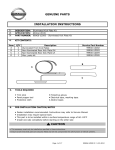
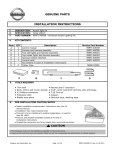
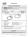
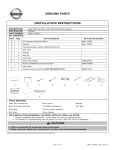
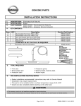
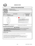
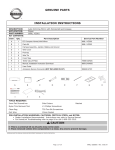
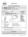
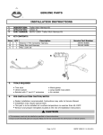
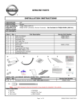
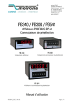
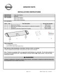
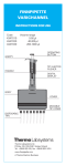
GENUINE PARTS
INSTALLATION INSTRUCTIONS
1.
2.
3.
DESCRIPTION: Accent light Kit
APPLICATION: Altima (2013)
PART NUMBER: 999F3 UZ000 - Accent Lighting Kit.
4.
KIT CONTENTS:
Item
A
B
C
D
QTY
1
1
1
1
Description
Control module
LED Lamp and harness assembly
Vehicle Interface Harness
Miscellaneous Parts Kit
Service Part Number
999F3 VZ000
999F3 UZ010
999F3 UZ020
999F3 UZ030
B
C
A
5.
TOOLS REQUIRED
●
●
●
●
6.
Trim stick
Needle nose pliers
#2 Phillips screwdriver
Drill Motor
●
●
●
●
3/16" drill bit
Electrical tape, masking tape.
Scissors
Protective cloth
PRE-INSTALLATION CAUTION/NOTES
● Dealer installation recommended. Instructions may refer to Service Manual
● Installation may require special tools
● This part is to be installed within a surface temperature range of 65-100ºF
CAUTION
● This accessory must only be installed as specified in these instructions.
● Ensure at all times that parts are securely fitted and will not compromise the safe function of vehicle systems.
Page 1 of 15
999F3 UZ000 II Rev. 4-5-2012
INSTALLATION INSTRUCTIONS - Accent lighting Kit
7. INSTALLATION OVERVIEW
8. CRITICAL STEPS
The following steps are critical and must be performed EXACTLY as specified to ensure
proper installation:
- Location of the lights must be followed exactly as described in this instruction.
- Posi-Tap™ instructions must be specifically followed as described.
Page 2 of 15
999F3 UZ000 II Rev. 4-5-2012
INSTALLATION INSTRUCTIONS - Accent Lighting Kit
9. VEHICLE PREPARATION
1)
2)
Apply parking brake
Confirm the vehicle is no longer in the default shipping state (Extended Storage Switch Pulled Up and BCM
in Transit Mode). Failure to confirm the vehicle has been removed from this state will result in the loss of
normal vehicle operation. The confirmation requires two checks:
2a) Locate the Extended Storage Switch
2b) Turn the ignition switch from "OFF" to "ON" position. If
in the cabin fuse block. Once located,
turn indicators illuminate for approx. 1 minute, the
check that it is in the "Customer"
vehicle is in shipping mode. To exit shipping mode,
position. See below for reference.
return the ignition switch to "OFF" position.
Simultaneously push the wiper and turn signal stalks
downward and hold for 2 seconds.
INVENTORY - UP
CUSTOMER - DOWN
NOTE: Typical vehicle
condition shown here.
Switch is easily identifiable
by the permanent, pushpull fuse holder.
Actual position on the fuse
block may vary, vehicle to
vehicle.
3) Record customer
radio presets.
NOTE: USE CAUTION WHEN REMOVING / RE-INSTALLING TRIM COMPONENTS TO AVOID
DAMAGE, SCRATCHES, BREAKING OF CLIPS AND / OR INTERIOR TRIM PANELS.
MOVE ALL TRIM COMPONENTS TO A PROTECTED AREA.
WARNING
Turn ignition switch to "ACC" position and move shift lever to full back (L)
position. Disconnect negative battery terminal before proceeding.
10.
Order of Installation
a. Interior preparation - remove panels.
b. Install - Passenger Footwell light.
c. Install - Driver Footwell light.
Page 3 of 15
d. Install - Vehicle interface.
e. System check.
f. Reinstall - Panels.
999F3 UZ000 II Rev. 4-5-2012
INSTALLATION INSTRUCTIONS - Accent Lighting Kit
11.
INTERIOR PREPARATION
Fig. 1
1. Carefully pry out center footwell panel
from the passenger side of the center stack.
NOTE: Be sure the front retainer clip stays
with the panel.
Fig. 2
2. Carefully pry off the dash side mask
by the passenger door.
Fig. 3
3. Remove three (3) phillips head screws
from the underside of the glovebox.
Page 4 of 15
999F3 UZ000 II Rev. 4-5-2012
INSTALLATION INSTRUCTIONS - Accent Lighting Kit
11.
INTERIOR PREPARATION
Fig. 4
4. Open the glovebox door. Remove five (5)
phillips head screws from inside the
glovebox compartment.
Fig. 5
5. Carefully pull out the glovebox assembly.
Disconnect the harness retaining clip.
Carefully unplug and remove the
harness connector and the glovebox lamp.
Disconnect the retractor cable. Fully remove
the glovebox assembly and set aside.
Note: Place glovebox assembly on a
protected work surface to avoid any
scratches or damage.
6. Trim out template "A" and tape into place inside center of panel as shown. The template should
be positioned along the left edge with the letter "A" in the lower left hand corner.
Mark and drill one (2) 3/16 inch holes at the locations indicated on the template. Remove the
template. Clean any flashing from the hole.
Fig. 6
Page 5 of 15
999F3 UZ000 II Rev. 4-5-2012
INSTALLATION INSTRUCTIONS - Accent Lighting Kit
12.
POSI TAP INSTRUCTIONS
Fig. 1
b)
a)
1) Tap vehicle wire.
a) Remove grey cap (slot side) from tap body.
b) Slide cap around vehicle wire.
c) Tighten the tap TIGHT with finger
pressure.
NOTE: Do not re-use the tap for subsequent
re-installation. Figures are not to scale
Grey Cap
Fig. 2
2) Inspect the tap to ensure correct installation.
NOTE: Avoid putting pressure on the vehicle
wire and tap for the remainder of the
installation.
i. Straight and evenly spaced all the way around
ii. Tight and minimize gap (wire jacket should
be crushed)
Fig. 3
e) Insert wire to here
Red C ap
c)
a)
d)
f) Tighten
Fig. 4
3) Inspect the tap to ensure correct installation.
a) Remove red cap (non-pierce) side from tap.
b) Remove the protective stub from the wire.
c) Insert wire through the non-pierce side
opening.
d) Spread the individual strands into fan
shape.
e) Insert wire into the tap body and ensure
that it is all the way in.
f) Tighten the tap TIGHT with finger
pressure.
4) Confirm the tapped accessory wire.
a) Inspect the tap to ensure correct
installation.
b) Test the signal to ensure that it is
working properly.
i. Straight and evenly spaced all around
ii. Tight and no gap and test the signal
...
Vehicle Harness
Fig. 5
b)
a)
5) Secure the tap.
a) Secure the tapped wire on the non-pierce
side to the body of the tap with electrical
tape (≥ 2 revolutions).
b) Secure the body to harness where vehicle
wire is being tapped with electrical tape
(≥ 2 revolutions).
Accessory
harness
Page 6 of 15
999F3 UZ000 II Rev. 4-5-2012
INSTALLATION INSTRUCTIONS - Accent Lighting Kit
13.
INSTALLATION
7. Using two (2) phillips screws from the inside of the glovebox cavity, securely attach the
two (2) "L" brackets with U nuts to the rear of the glovebox.
Fig. 7a
Fig. 7b
Fig. 8
8. Secure the harness the the back of the
glovebox with foam tape as shown.
Fig. 9
9. Locate the glovebox lamp. Strip away approx.
3/4" of insulation from the base of the lamp
connector.
Page 7 of 15
999F3 UZ000 II Rev. 4-5-2012
INSTALLATION INSTRUCTIONS - Accent Lighting Kit
13.
INSTALLATION
CAUTION
●
If a vehicle wire is being used by another accessory and a posi-Tap is present, tap
the accessory wire NOT the vehicle wire.
Fig. 10
Fig. 11
10. Looking at the rear of the connector, locate
the left wire. Using a posi-tap, connect the
blue wire from the power harness to the
left wire at the back of the glovebox lamp
connector.
11. Follow this finishing procedure on all
posi-taps. Leave a short length of
wire extended past the posi-tap and
bend down as shown. Use electrical
tape to secure the extra wire against the
posi-tap with at least two revolutions.
Note: Make sure that the end of the wire is
completely covered by the tape.
Fig. 12
12. Locate the passenger side Accessory
Connector plug. It will be behind the
glovebox on the right side.
Note: A previously installed accessory may
be present. If so, carefully remove the
accessory connector harness from the
accessory connector plug before
posi-tapping. It is recommended that
all posi-tapping be completed before
reattaching the accessory connector
harness to the plug.
Page 8 of 15
999F3 UZ000 II Rev. 4-5-2012
INSTALLATION INSTRUCTIONS - Accent Lighting Kit
13.
INSTALLATION
Fig. 13
13. Using a posi-tap, connect the Black wire
from the power harness to the Black wire
on the Accessory Connector Harness.
Using a posi-tap, connect the Green wire
from the power harness to the Pink
wire on the Accessory Connector Harness.
Using a posi-tap, connect the Brown wire
from the power harness to the Yellow
wire on the Accessory Connector Harness.
Note: Be sure NOT to posi-tap through
the shrink wrap tubing.
Fig. 14
HARNESS NOT INCLUDED IN KIT.
REFERENCE PART NUMBER
999Q9 AY000.
14. Wrap the posi-taps with foam tape to
prevent rattle.
Plug the Accessory Connector Harness into
the vehicle connector plug on the
passenger side.
Fig. 15
15. Place the glovebox assembly back into
the passenger footwell. Reconnect the
valet wiring connector and the glovebox
lamp connector. Secure the power harness
to the back of the glovebox with a cable tie
as shown.
Page 9 of 15
999F3 UZ000 II Rev. 4-5-2012
INSTALLATION INSTRUCTIONS - Accent Lighting Kit
13.
INSTALLATION
Fig. 16
16. Reinstall the glovebox. Reinstall five (5)
phillips head screws from inside the
glovebox compartment.
Fig. 17
17. Reinstall three (3) phillips head screws
from the underside of the glovebox.
Fig. 18
18. Reinstall the dash side mask.
Page 10 of 15
999F3 UZ000 II Rev. 4-5-2012
INSTALLATION INSTRUCTIONS - Accent Lighting Kit
13.
INSTALLATION
DRIVER SIDE LED MODULE INSTALLATION
Fig. 19
19. Carefully pry out center footwell panel
from the driver side of the center stack.
NOTE: Be sure the front retainer clip stays
with the panel.
20. Feed the driver side LED module through behind
the center stack to the driver side footwell.
Fig. 21
21. Prepare to mark and drill locations for the driver side LED Module. Measure and mark 25mm over
from the right edge of the diagnostic port. Measure and mark 15mm in from the bottom edge
of the steering finisher.
22. Carefully drill a 3/16 inch hole at this first location.
23. Place the driver side LED module in the inside of the panel with the LED facing downward.
Use one (1) phillips screw from the outside of the panel to mount the driver side LED module
as shown at the first hole. Rotate the module into position, making sure the LED is not
covered by the edge of the panel. Use the bracket on the LED module to mark and drill the
second hole location. Insert the second phillips screw and securely fasten the module.
Page 11 of 15
999F3 UZ000 II Rev. 4-5-2012
INSTALLATION INSTRUCTIONS - Accent Lighting Kit
13.
INSTALLATION
Fig. 24
24. Route driver side harness under the
dashboard towards the center stack.
Secure to the knee bolster with a cable
tie as shown.
Note: The view shown here is looking up
under the dash from behind, near the
center stack.
Fig. 25
25. Route driver side harness through
the center stack and out towards the
passenger footwell. Secure the harness
the the HVAC duct with foam tape as shown.
Note: A section of corrugated flex tubing is
included on the harness. This tubing
should be positioned behind the center
stack to protect the wiring from any
metal edges.
Fig. 26
Note: Attach one (1) 58mm x 82mm
foam tape to the underside of the
accessory control module, covering
the screw in the center.
26. Place one (1) piece of foam tape over
the top of the accessory controller.
It should be on the opposite side of the
sticky foam tape covering the screw.
Note: Do NOT pull cover off tape on
controller at this time.
Page 12 of 15
999F3 UZ000 II Rev. 4-5-2012
INSTALLATION INSTRUCTIONS - Accent Lighting Kit
13.
INSTALLATION
Fig. 27
27. Route harnesses under the center stack.
Plug the harnesses into the control module.
Fig. 28
28. Peel the cover off the tape on the controller
and securely place the controller on the
metal bracket under the center stack.
Fig. 29
29. Carefully peel back the passenger side
carpet. Route the wiring that leads to the
Accessory Connector along the top of the
styrofoam filler panel. Secure the wiring with
foam tape in three (3) places and tuck it
behind the styrofoam as shown. Secure the
wiring along the exisiting harness on the
right side with cable ties.
Note: Do NOT secure the wiring to the
drain tube in any way.
Page 13 of 15
999F3 UZ000 II Rev. 4-5-2012
INSTALLATION INSTRUCTIONS - Accent Lighting Kit
13.
INSTALLATION
Fig. 30
30. Bundle any exess wiring and secure with
a cable tie under the center stack at the
module as shown.
Secure the wiring from the glovebox lamp
to the underside of the vent ducting with
foam tape as shown.
Note: Be sure cables do not touch footwell
panel, to prevent rattling.
31. Reinstall the driver side footwell panel (see Fig. 18).
32. Reinstall the passenger side footwell panel. (see Fig. 1).
NOTE: Trim all cable ties. Check installation.
Page 14 of 15
999F3 UZ000 II Rev. 4-5-2012
INSTALLATION INSTRUCTIONS - Accent Lighting Kit
14.
CHECK OUT
(1) Shut all doors on the vehicle.
(2) Wait untill all interior lamps go out.
(3) Turn on the headlamps.
(4) Verify that both LEDS come on.
(5) Check the trim for a proper, flush fit after re-installing the interior components.
(6) Clean the interior of the vehicle.
(7) Inspect the vehicle interior and exterior for damage.
(8) Check and clear trouble codes (DTC).
(9) If this vehicle will be returned to a dealer lot or showroom for an extended period
of time, be sure the extended storage switch is placed in the "inventory" position.
(Refer to section 9 - Vehicle Preparation)
(10) If vehicle is NOT going into storage, reset the radio presets to the recorded settings.
Page 15 of 15
999F3 UZ000 II Rev. 4-5-2012
INSTALLATION INSTRUCTIONS - Accent Lighting Kit
15.
BILL OF MATERIALS
Nissan Universal Accent Lighting Kit - 999F3 UZ000
Qty
Part Number
1 Accent Lighting Controller (Single Color - White)
Parts Contained in Bag Labelled 'Installation Kit'.
1
999F3 VZ000
2 LED Lamp Assembly (w/Harness)
1
999F3 UZ010
3 Vehicle Interface Harness
1
999F3 UZ020
4 Miscellaneous Parts Kit
1
999F3 UZ030
5
CABLE TIE 4" BLACK
5
6
80 X 30 X 5MM THICK FOAM
8
7
POSI-TAP (20AWG/0.5mm2 TYPE)
4
8
SCREW N8, 1/2" LG HEAD, BLACK
4
9
MODULE ADHESIVE PAD 53MM X 33MM
1
10
WHITE PAPER LABEL 14MM X 33MM
1
11
POLYTHENE 8" X 12" BAG
3
12
POLYTHENE 102" X 140" BAG
1
13
PACKING ID LABEL
1
14
CABLE TIE 15" BLACK
3
15 Website Instructions w/Parts List
1
999V2 AW000
16 Installation Instructions (Website)
0
999F3 UZ000 II
BOM
999F3 UZ000 II Rev. 4-5-2012
INSTALLATION INSTRUCTIONS - Accent Lighting Kit
16.
MECHANIZATION
Mechanization
999F3 UZ000 II Rev. 4-5-2012
INSTALLATION INSTRUCTIONS - Accent Lighting Kit
17.
TEMPLATE A
Template
999F3 UZ000 II Rev. 4-5-2012