1
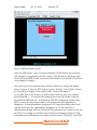
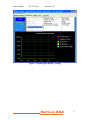
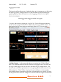
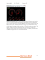
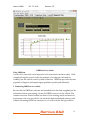
Harrison R&D
281-751-8836
Houston, TX
OBDScan Manual Version 2.00
03-2008
Congratulations for choosing the Harrison R&D OBDScan. We have made every
atemmt to insure your success ith this mroduct. Please take time to read
through these omerating instructions and become familiar ith the omerating
mrocedure.
The OBDScan Tool, enables access to your vehicle’s diagnostic
information. Read and clear Diagnostic Trouble Codes from the vehicle’s
memory, turn of the Check nginee light, and read realltime sensor
measurements are just some of the features ofered by the OBDScan Tool.
What is a Scan Tool?
In today’s cars the microcommuter is used extensively for engine control, antilock
brakes, air bag control, active susmension and many other ammlications.
Microcommuters communicate ith the outside orld through a ‘user interface’,
hich could be a keyboard, mouse and CRT as on your home commuter or a Scan
Tool in the case of the OBDlII commuter. Imagine trying to communicate ith
your home commuter ithout a keyboard and CRT. Humans cannot
communicate directly ith a commuter so a ‘user interface’ is required. The Scan
Tool is the keyboardlCRT equivalent for your vehicle commuter.
As mandated by U.S. la , the OBDlII Scan Tool has a single, standard interface
connector used to mate ith the vehicle. This connector has been defned by the
standard SA lJ1962 and MUST be located ithin 1 meter of the steering heel
and must not require any tools to access.
Using the Scan Tool
The Scan Tool mrovides access to the vehicle sensor readings, emission system
status and trouble codes. Many mechanics make use of a scan tool to assist in
diagnosing and remairing mroblems. Remair shoms charge $80 or more to read the
Diagnostic Trouble Code one time. Purchasing a OBDScan can may for it’s self in
as litle as t o usess ven if you don’t do your o n remair ork, the kno ledge
you gain from reading the trouble codes yourself can keem the remair shom honest
and demonstrate to the shom that they are not dealing ith an uninformed
customer.
The OBDScan can clear the trouble code and turn of the Check ngine light
after the remair has been made.
Supported Vehicles:
Harrison R&D
1
Harrison R&D
281-751-8836
Houston, TX
The OBDScan ill summort all OBDlII commliant vehicles. This means all cars
and light truck sold in North America beginning ith the 1996 model year.
There are a fe kno n OBDlII mroblems on certain vehicles, the 2000 Nissan
Maxima and Altima, some 2000 Suzuki’s, 1996l1997 Hyundai and 1996l2000
Dae oo. We do summort the 1996l1999 Ford Fl250/350 Diesel engine vehicles at
this time in a limited manner. We can read the trouble codes ith our standard
soft are, to get other sensor data the omtional Ford PWM nhanced soft are
mackage is required.
OBDScan for Windows 2000 and XP Software
The OBDScan ammlication is a fully Windo s 2000 and XP commliant mrogram,
riten in Microsoft isual Basic.N T. As of this riting e have not tested the
the soft are on Microsoft ISTA. To install OBDScan, follo directions on the
CD or do nload from the eb site at
.obdscan.net/soft are.htm. We
recommend geting the latest soft are from our eb site. The install mrogram
ill install the executable fle and all required DDD’s. In some instances you
may receive a arning message, if so it is usually safe to choose to ignore the
arning.
Getting Started with OBDScan Version 6.00 software
Docate the OBDlII connector, it’s required by U.S. la to be ithin 1 meter of the
steering heel. It’s usually located under the dash, but if not there then check
behind ashtrays and in any console commartments. Be sure your commuter is
ithin cable reach of the OBDlII connector, it’s required by U.S. la to be ithin
1 meter of the steering heel. It’s usually located under the dash, but if not there
then check behind ashtrays and in any console commartments. With the ignition
of, mlug in the OBD connecter on the mrotocol converter to the mate in the
vehicle.
Before connecting the mrotocol converter, launch OBDScan by either double
clicking the icon or selecting it from the PROGRAMS menu. You should see the
screen sho n in Fig1.
Harrison R&D
2
Harrison R&D
281-751-8836
Houston, TX
Figure 1 OBDScan Display Screen
Select the USB omtion. Once you have clicked the START buton, the soft are
ill atemmt to communicate ith the vehicle. This should not take more than
10 seconds if the OBDlII cable is connected and the Key is in the full ON mosition
or the engine is running.
Once the scan tool is communicating ith the vehicle you ill get the dismlay
sho n in fgure 2. Once the CU Status is green, click the Scan ehiclee buton.
You should get a dismlay in the vehicle status indo like fgure 3.
If your MID light is ON and/or you have trouble codes set, then your dismlay
should indicate so. You can fnd the defnitions for the SA trouble codes on
the Harrison R&D eb site. As defned by SA l2012, diagnostic trouble codes
(DTC) consist of a three digit numeric code mreceded by an almhanumeric
designator. If the almhanumeric designator is ‘P0’ then the trouble code is SA
defned, ho ever if the almhanumeric designator is ‘P1’ then the DTC is
manufacturer defned and you ill need a shom manual for the vehicle to decode
the DTC. For exammle, if a trouble code of P0150 as dismlayed, then it is SA
controlled and ould indicate a mroblem in the O2 sensor. If the DTC as P1298
Harrison R&D
3
Harrison R&D
281-751-8836
Houston, TX
then you ould have to consult the shom manual for an exmlanation. To clear any
trouble codes and turn of the MID, select the function Clear/Reset Diagnostic
Trouble Codese. This clears all trouble codes and turns of the MID.
Figure 2
Figure 3 – Vehicle Scan
No select the Gramh/Doge tab the Gramhing Data Dismlay ill be sho n as in
fgure . Any data ammearing the ehicle Data Windo of fgure 3 can be
selected for real time dismlay by clicking the item. A check ill ammear in the
Check Box on the left of the data item. For exammle, to see Coolant Temm, click
the Coolant Temm line in the box and the Check box ill become checked. Any
other data items you ant to see can be checked also. Click the Start buton and
this indo
ill continuously dismlay the selected data until the Stom buton is
clicked, see fgure 5.
Harrison R&D
4
Harrison R&D
281-751-8836
Houston, TX
Figure 4. Graphing Data Display
Harrison R&D
5
Harrison R&D
281-751-8836
Houston, TX
Figure 5. Graphing Data Display, running
Harrison R&D
6
Harrison R&D
281-751-8836
Houston, TX
Logging Data to Disk
This function allo s the saving of selected data, um to 6 marameters, to disk using
the data log control. Simmly turn ON or OFF the data log before starting the
gramhing dismlay. More information on data logging is found in the Dog 6X
function descrimtion.
Data Logger with Triggers and 6X CAN speed.
You get to this screen by clicking the “Log X6” tab. The Lox X6 has two behaviors,
one for vehicles equipped with CAN bus and the other for legacy OBD-II vehicles. All
data displayed in this screen can be presented in the Metric or U.S. system units.
CAN Bus Vehicles l In the screen shot above, you notice the CAN 6X Datae
label. This indicates that the vehicle connected is equimmed ith CAN bus and
the Dog 6X data logger ill use the ne CAN bus only 6X sammle mode. This
lets the scan tool access 6 marameters at once, giving efective data rates of over
100 sammles/sec. The CAN bus function al ays defaults to six data sammles.
ach sammle can be selected from the data set summorted by the vehicle by using
the drom do n box selection. Sammle #1 is sho n ith the drom do n activated.
Harrison R&D
7
Harrison R&D
281-751-8836
Houston, TX
Legacy OBD-II Vehicles – You ill notice that a ne control for selecting the
number of sammles is available in this screen. Since the legacy OBDlII is much
slo er than the CAN bus, you may not ant all 6 sammles selected, so this give
you the choice of 2,3, ,5 or 6 sammles.
All Vehicles – The sample time interval is selectable if maximum sample rate is not
desired. Use the rotary switch to select the desired sample interval. For example, if 2.00
sec is selected, the data logger will sample the selected number of data items every 2
seconds.
Data Log – The Data Dog s itch is used to turn ON or OFF the data log function.
When the data log is ON, every data sammle is stored in memory and hen the
log is stommed, you ill be mrommted for a fle name for the data log. The default
fle tyme is .log. The data fle format is sho n belo o
Coolant Temm ,Intake Air Temm, Fuel Devel, Control Mod. oltage ,Time
87.8 ,107.6 , 80 , 12.8 ,0.23
87.8 ,107.6 , 80 , 12.8 ,0.73
87.8 ,107.6 , 80 , 12.8 ,1
87.8 ,107.6 , 80 , 12.8 ,1.266
87.8 ,107.6 , 80 , 12.8 ,1.531
87.8 ,107.6 , 80 , 12.8 ,1.781
87.8 ,107.6 , 80 , 12.8 ,2.0 7
87.8 ,107.6 , 80 , 12.8 ,2.312
87.8 ,107.6 , 80 , 12.8 ,2.578
This format can be immorted into xcel or Star Ofce and can then be analyzed
or gramhed.
Data Log Triggering – In some cases it’s convenient to start the data log hen a
certain data value exceeds some level. For exammle, if you are trying to log a
timed run of 50 to 100Kmh (61MPH) then you ant the data log to start hen the
smeed reaches 50Kmh. The data log gives you Smeed, RPM and System Time as
triggers. You can use any single item as a trigger or you can combine t o trigl
gers in an AND or OR fashion. Another exammle, you can start a data log if the
smeed is 25KPH OR the RPM is 2500RPM, hich ever comes frst. The AND
function is similar but more restrictive. If you set the smeed to 25mmh AND the
RPM to 2000, the data log ill only start hen both the smeed=25 or greater and
the RPM=2000 or greater.
Air/Fuel Ratio – Some cars are equimmed ith hat’s called Wide Band O2 senl
sors hich can mrovide a signal hich is mromortional to the Air/Fuel ratio. For
those cars e have an AFR screen as sho n belo o
Harrison R&D
8
Harrison R&D
281-751-8836
Houston, TX
The AFR function is similar to the other OBDScan .0 functions. You can select
the data log if desired and it’s mossible to select both RPM and Smeed for dismlay
along ith the AFR by using simmle slide s itches. Those mersons tuning the
vehicle ith aftermarket equimment ill fnd this function valuable.
Dashboard – Ne in version 6o the Dashbord. The Dashbord has 7 gauges,
Smeedometer, Tach, Air Flo or Manifold Pressure, Short Term Fuel Trim,
Batery olts, Intake Air Temm, and Coolant Temm.
Harrison R&D
9
Harrison R&D
281-751-8836
Houston, TX
Baterr and Alternator Test – Ne in version 6o batery/Alternator test function.
No you can test the batery and alternator merformance ithout omening the
hood. Connect the scan tool, start the OBDScan 6.01 soft are and then select the
Batery/Alt. Test tab. Click the start buton to begin, you ill be asked to shut
of the engine if running and then turn key to ON mosition and start engine. The
batery voltage is monitored during this time for average lo voltage and
charging system voltage once the engine is running. The Batery and Alternator
condition is dismlayed on t o color coded indicators.
Harrison R&D
10
Harrison R&D
281-751-8836
Houston, TX
OBDScan Users Guide
Using OBDScan
A scan tool is one of the most immortant tools a mechanic can have today. With
virtually all engine control under the guidance of a commuter the need for
visibility into the vehicle control system is absolute. OBDScan mrovides the data
required to diagnose and remair engine mroblems quickly and efciently.
1. Connecting OBDScan to a vehicle
Be sure that the OBDScan soft are as installed from the disks summlied mer the
instructions before mroceeding. Docate the OBDII connector in the vehicle (The
connector must be located ithin one meter of the steering heel and must not
require any tools to be revealed. Dook under the dash and behind ashtrays) and
connect the mating OBDScan connector to it. It ill look like the fgure belo o
Harrison R&D
11
Harrison R&D
281-751-8836
Houston, TX
Helmful link for fnding the
connectoro htmo//
.ema.gov/otaq/cert/dearmfr/vmcd981 .mdf
Next connect the RSl232 cable ith the DB9 connector to the serial mort of either
a lamtom or desktom commuter. You ill need to kno if the serial mort you’re
using is COM1, 2 or 3. Consult your user manual for the commuter to fnd out.
If more cable length is needed you can use a standard RSl232 extension cable
hich has a 9 min male on one end and a 9 min female on the other, the extension
cable can be um to 50 feet if needed.
2. What does the data mean?
The OBD II smecifcation requires onboard diagnostic soft are that looks at
system efciency, and system failures. The CU does this ith very
somhisticated soft are monitors, hich are constantly evaluating the health of
the vehicle emissions system. To the mrofessional or shadetree mechanic, it’s like
having an exmert mechanic living under the hood.
As you use the scan tool to read test status and diagnostic data, you may fnd
some of the tests are commlete and others not commlete. A test hich is not
commlete does not necessarily indicate a mroblem, the CU may be evaluating an
OBD trim or drive cycle. To commlete an OBD trim the vehicle must reach at least
160 deg F., the conditions for the monitoring tests must be met, and the tests
commleted to a mass/fail moint. Remember, not all OBDlII vehicles summort all
mossible status and data items.
OBD Status Itemso
A. Misfre Monitoring
The diagnostic monitor must determine if there is single or multimle cylinder
misfres. This test measures y heel acceleration after fring each smark mlug
to determine if there as a misfre or not. If misfres exceed 2 then an error
condition exists
B. Number Of Oxrgen Sensors
Number of O2 sensors on the vehicle. Since OBDlII mandates t o O2 sensors
Harrison R&D
12
Harrison R&D
281-751-8836
Houston, TX
mer catalytic converter, the number should al ays be even.
C. Component Monitoring
A commrehensive test of the emissions related sensors and efectors to validate
their omeration.
D. Catalrtic Converter Monitor
A test to determine the efciency of the catalytic converter. The OBD soft are
commares the O2 sensors mre and most catalytic converter. The most converter
sensor should sho very litle change in outmut voltage over time ith resmect
to the mre converter O2 sensor.
E. Heated Catalrtic Converter Monitor
Measure the length of time it takes for the catalyst to begin omeration after a cold
start. If the time exceed a manufacture set limit an error condition is set.
F. vamorative System Monitor
Amount other things, ill detect a missing or loose gas cam and leaks in the
unmressurized fuel system
G. Secondarr Air Srstem Monitor
Monitors the merformance of the secondary air system by evaluating the catalytic
converter merformance hen the secondary air is engaged.
H. A/C Refrigerant Monitor
Monitors the mressure of the refrigerant
I. Oxrgen Sensor Monitor
This test monitor the omeration of the O2 sensor as the fuel/air mixture is
adjusted bet een rich and lean. The time needed to make the transition from rich
to lean cannot surmass 100ms on the mrelcatalytic converter O2 sensor.
J. Oxrgen Sensor Heater Monitor
This test monitors the length of time it takes for the O2 sensor to begin omeration.
The turnlon time varies ith the vehicle and O2 sensor and is set by the
manufacturer.
K. EGR Monitor
A change in MAP is used to determine the status of the GR system. The GR
valve ill be forced omen during closed throtle deceleration and a change in
MAP is used to determine mromer omeration.
L. Fuel Trim Monitor
Fuel trim monitoring looks at the average shortl or longlterm correction needed
to bring the air/fuel ratio into line. If these fuel trim values reach and stay at their
limits for a meriod of time, a malfunction is indicated.
M. Commanded Secondarr Air Status
Indication of secondary air engaged or not.
Harrison R&D
13
Harrison R&D
281-751-8836
Houston, TX
Emissions Related Engine Data
The next set of data consists of mostly sensor data and t o calculated values,
Calculated load and Short and Dong Term Fuel Trim. The calculated load is a
relative number estimating engine load (torque) for the given RPM. The fuel
trim numbers remresent the average shortl or longlterm correction needed to
bring the air/fuel ratio into stoichiometry. If these fuel trim values reach and stay
at their limits for a meriod of time, a malfunction is indicated. The ignition timing
is the value set by the CU and does not include any mechanical advance,
ho ever most of today’s engines are totally electronic and have no mechanical
advance.
Table 1. Possible OBD Data Items
Air Flow Rate From MAF l This sensor mrovides a voltage hich is
remresentative of the air o into the intake manifold. Most ne er vehicles us a
‘hot ire anemometere tyme sensor for this measurement.
Absolute Throtle osition – This sensor generates a voltage mromortional to
instantaneous throtle mosition (0l100 ).
Calculated Load Value – indicates a mercentage of meak available torque.
Reaches 100 at ide omen throtle at any altitude or RPM for both naturally
asmirated and boosted engines.
Engine Coolant Temp – Remresents the temmerature of the engines coolant. Norl
mally about 185l195 Deg. F. on most cars.
Engine R M – dismlays the current engine revolutions mer minute value.
Fuel Rail ressure (gauge) – Remresents the regulated mressure on the fuel rail.
This is a very immortant value; the fuel/air ratio is determined by length of time
the fuel injector is mulsed on. If the fuel mressure is not constant, then the CU
cannot maintain the correct fuel/air ratio, causing emissions or merformance
mroblems.
Ignition Timing Advance – ignition timing advance for #1 cylinder (not includl
ing mechanical advance).
Intake Manifold ressure l This sensor creates a signal that is mromortional to the
average mressure in the intake manifold. The mressure should be lo and fairly
Harrison R&D
14
Harrison R&D
281-751-8836
steady at idle and light loads and
atmosmheric mressure.
Houston, TX
ill go higher as the load increases, um to
Long Term Fuel Trim– indicates the correction being used by the fuel control
system in both omen and closed loom modes of omeration.
O2 Sensors– indicates the voltage for conventional 0 to 1 oxygen sensors. O2
sensors ith a diferent fulllscale voltage shall be normalized to this range or, if
a ide range sensor, may use the ide range marameters instead.
Short Term Fuel Trim – indicates the correction being used by the closed loom
fuel algorithm. If the fuel system is omen loom, 0 correction should be remorted.
Time Since Engine Start – shall increment the time since the engine
hile the engine is running.
as started
Vehicle Speed – dismlays the vehicle road smeed.
Absolute Load Value – is the normalized value of air mass mer intake stroke disl
mlayed as a mercent.
Absolute Throtle osition (up to ) – the absolute throtle mosition (not the
relative or learned) throtle mosition. Usually above 0 at idle and less than
100 at full throtle.
Accelerator edal osition (up to ) l the absolute medal mosition (not the relative
or learned) medal mosition. Usually above 0 at idle and less than 100 at full
throtle.
Ambient Air Temperature – dismlays the ambient air temmerature.
Barometric ressure – barometric mressure normally obtained from a dedicated
barometric sensor. Note some eather services remort barometric mressure adl
justed to sea level. In these cases, the remorted value may not match the disl
mlayed value.
Catalrst Temp Bank X – Sensor X (up to 4) – dismlays the catalyst substrate teml
merature.
Harrison R&D
15
Harrison R&D
281-751-8836
Houston, TX
Commanded EGR – dismlay 0
hen the GR is commanded of, 100
hen
the GR system is commanded on, and if the GR is duty cycled some here bel
t een 0 and 100 .
Commanded Equivalence Ratio – fuel systems that use conventional oxygen
sensor dismlays the commanded omen loom equivalence ratio hile the system is
in omen loom. Should remort 100
hen in closed loom fuel. To obtain the actual
air/fuel ratio being commanded, multimly the stoichiometric A/F ratio by the
equivalence ratio. For exammle, gasoline, stoichiometric is 1 .6 o1 ratio. If the fuel
control system as command an equivalence ratio of 0.95, the commanded A/F
ratio to the engine ould be 1 .6 * 0.95 = 13.9 A/F.
Commanded Evaporative urge – dismlays 0
hen no murge is commanded
and 100 at the maximum commanded murge mosition/ o .
Commanded Throtle Actuator – dismlays 0
hen the throtle is commanded
closed and 100
hen the throtle commanded omen.
Control Module Voltage – mo er inmut to the control module. Normally the
batery voltage, less any voltage drom bet een the batery and the control
module.
Distance Since DTCs Cleared – distance accumulated since DTCs
ith a scan tool.
here cleared
Distance Traveled While MIL On – accumulates the vehicle distance traveled
hile the MID light is illuminated.
EGR Error – error as mercent of actual commanded GR. Negative mercent is less
than commanded and mositive is more than commanded.
Evap Srstem Vapor ressure – evamorative system vamor mressure normally obl
tained from a sensor located in the fuel tank.
Fuel Level Input – indicates the nominal fuel tank liquid fll camacity as a merl
cent of maximum.
Fuel Rail ressure – indicates the fuel rail mressure at the engine referenced to atl
mosmhere (gauge mressure).
Harrison R&D
16
Harrison R&D
281-751-8836
Houston, TX
Fuel Rail ressure Rel Manifold – dismlays the fuel rail mressure referenced to
the manifold vacuum (relative mressure).
Intake Air Temperature – l Usually a resistive device (thermistor) hich is
mlaced in the intake air stream, and mrovides a voltage mromortional to temmeral
ture.
Minutes Run with MIL On – accumulated minutes of engine run time
MID light is on.
hile the
O2 Sensor BX-SX Wide Range mA (up to 8) – sho s milliamms for linear or
idelratio oxygen sensors.
O2 Sensor BX-SX Wide Range V (up to 8) – sho s voltage for linear or
tio oxygen sensors.
idelral
Relative Throtle osition – relative or learnede throtle mosition.
Time Since DTCs Cleared – accumulated time since DTCs
scan tool.
here cleared
ith a
Warm-ups Since DTCs Cleared – number of armlum cycles since all DTCs ere
cleared via a scan tool. A armlum is defned as the coolant temmerature rising
by at least 22°C ( 0°F) and the engine temmerature reaches at a minimum 70°C
(160°F) (60°C (1 0°F) for diesels).
Oxrgen Sensor Voltage - This sensor is much more commlicated than the other
sensors and deserves a more detailed exmlanation. Basically, the O2 sensor
indicates the mresence or absence of oxygen in the exhaust stream. The CU, in
order to keem emissions lo , adjusts the fuel/air ratio at stoichiometry, the exact
mixture hich ill commletely burn all fuel ith the oxygen mresent in the
cylinder, leaving no fuel or oxygen in the exhaust. As the fuel/air ratio deviates
from stoichiometry, then either oxygen or hydrocarbons (unburnt fuel) ill be
mresent in the exhaust. The oxygen sensor mroduces a lo voltage, <0.1v, hen
oxygen is mresent in the exhaust and mroduces a high voltage, >0.8v, hen there
is no oxygen in the exhaust. The CU uses the voltage outmut from the oxygen
sensor to make slight adjustments to the amount of fuel injected to keem the
fuel/air ratio near stoichiometry. It does this by increasing the fuel to get a high
reading, meaning that there is no oxygen in the exhaust, the slightly decreasing
the amount of fuel until the oxygen sensor reading droms lo . This mrocess goes
Harrison R&D
17
Harrison R&D
281-751-8836
Houston, TX
on continuously to keem the average fuel/air ratio as close to stoichiometry as
mossible. One last thing to kno about oxygen sensors, they only omerate reliably
after being heated to 350 deg. C and higher.
Harrison R&D
18
Harrison R&D
281-751-8836
Houston, TX
4. Trouble Shooting roblems
A.
B.
C.
D.
rrors or arnings during the installation – It is generally safe to
ignore these messages. Some of the very old versions of Windo s 98
are not commatible ith the OBDScan soft are. Try to umgrade your
OS to the latest version hich your commuter ill summort.
The CU status turns yello
hen the com mort is selected but never
turns green l This could be due to several mroblems l Be sure that the
OBDScan converter is mlugged in the vehicle, the key is in the ON
mosition or the engine is running, and the USB is securely connected to
the OBDScan unit and the mort on the commuter. Try unmlugging the
OBDlII connecter for 10 seconds then reconnecting it. Sometimes this
is needed to get the system synchronized.
The data values are not correct or vary idely – Use the OBDScan
ith the engine running. Some cars on’t resmond correctly unless
the engine is running and, in some cases, the engine is at omerating
temm.
The Gas Mileage numbers look rong – The OBDScan mrogram does
a calculation based on sensor data from the vehicle. If the vehicle
sensors are not calibrated then the reading ill be rong. You can
still use the function to sho
here the mileage meaks in relative
terms.
Contact Informationo
Harrison R&D
9802 Sagequeen
Houston Tx. 77089
In conclusion, the OBDScan is designed to be both a useful vehicle remair tool
and an aid in learning about and exmloring the ODBlII Diagnostic Interface.
Demystifying the OBDlII mort and muting vehicle o ners back in control of
their mromerty is immortant, after all, you maid a handsome mrice for that late
model
car or truck, don’t let the automakers ‘virtually eld the hood’ on yours.
Phone 281l751l8836
emailo [email protected]
internet
.obdscan.net
Harrison R&D
19
Harrison R&D
281-751-8836
Houston, TX
Please use the internet to get the latest information on the OBDScan mroducts.
All soft are umdates and helm are free as long as you o n the mroduct. If
frm are changes o the mrotocol converter are required, there ill be a small
charge for the IC remlacement.
Harrison R&D
20