1
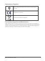
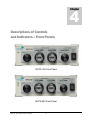
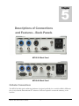
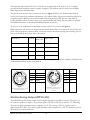
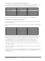
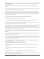
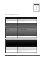
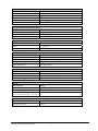
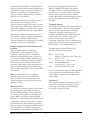
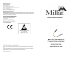
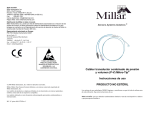
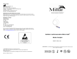
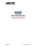
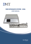
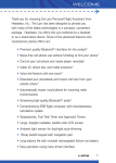
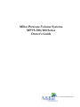
Millar Pressure-Volume Systems
MPVS-300/400 Series
Owner’s Guide
AT THE HEART OF SENSOR INNOVATION®
This document was, as far as possible, accurate
at the time of printing. Changes may have been
made to the software and hardware it describes
since then, though Millar Instruments reserves
the right to alter specifications as required. Latebreaking information may be supplied
separately.
Product:
MPVS-300 (P/N 753-2057)
MPVS-400 (P/N 753-2058)
Hardware: Millar Instruments
Documentation: Millar Instruments
Document Number: 004-2142 Rev. B
Copyright © 2004, 2005.
Trademarks of Millar Instruments
Millar, Mikro-Tip and At the Heart of Sensor
Innovation are registered trademarks of Millar
Instruments, Inc.
Millar Instruments, Inc.
6001-A Gulf Freeway
Houston, TX 77023-5417
United States
Other Trademarks
Web: www.millarinstruments.com
E-mail: [email protected]
PowerLab, Chart and specific names of
recording units such as PowerLab 4/25 are
registered trademarks of ADInstruments Pty
Ltd.
All rights reserved. No part of this document
may be reproduced by any means without the
expressed written consent of Millar
Instruments, Inc.
Pentium is a registered trademark of the Intel
Corporation.
Redel is a registered trademark of the Lemo
Corporation.
Windows is a registered trademark of Microsoft
Corporation in the United States and/or other
countries.
All other trademarks are the property of their
respective owners.
MPVS-300/400 Owner's Guide
i
Table of Contents
1 Safety Notes 1
5 Descriptions of Connections and Features – Back
Panels 9
Intended Use 1
Catheter Connections 9
Emergency Access to Power Cord 1
Monitor/Analog Output (MPVS-400) 10
Applicable Safety Standards 1
Analog Output (MPVS-300) 11
Explanation of Symbols 2
Analog Input (MPVS-400) 11
Preventative Inspection and Maintenance 2
I2C Bus (MPVS-400) 11
2 Product Overview 3
USB Connector (MPVS-400) 11
Earth Ground Terminal 11
3 Computer Requirements 5
Power Switch 12
Power Input 12
4 Descriptions of Controls and Indicators – Front
Panels 6
Cooling Fan (MPVS-400) 12
Pressure Transducer/Calibration Switch 7
6 Setup and Use 13
Pressure Transducer Balance Controls 7
MPVS-300 Quick Start 13
Lighted Pressure Output Indicators 7
MPVS-400 Quick Start 15
Volume Transducer/Relative Volume Units (RVU)
Calibration Switch 7
Connecting the MPVS-400 to a Computer 17
Lighted Conductance/Volume Output Indicator 8
USB Connection 18
Segment Select Switch 8
New Hardware Wizard 19
Lighted Power Indicator 8
Appendix A 20
Lighted Status Indicator (MPVS-400 only) 8
Troubleshooting 20
Appendix B 26
Technical Specifications 26
Warranty Agreement 28
MPVS-300/400 Owner's Guide
ii
1
Chapter
Safety Notes
Intended Use
Millar Instruments Pressure-Volume Systems (MPVS) have been designed for use in animal research
applications. They are not intended for clinical or critical life-care use and should never be used for these
purposes, or for the prevention, diagnosis, curing, treatment, or alleviation of disease, injury, or handicap.
Emergency Access to Power Cord
The power cord must not be blocked by other equipment or any panel or fixture. In case of an emergency, the
user must be able to reach the cord to disconnect it.
Applicable Safety Standards
The MPVS-300 and MPVS-400 meet the requirements of the standards listed in the table below. Further
information is available upon request.
Standard
EN61010-1:2001
EN61326-1: A1:1998 and A2:2001
MPVS-300/400 Owner's Guide
Title
Product Safety for Laboratory Equipment
EMC Requirements for Measurement, Control
and Laboratory Use
1
Explanation of Symbols
Refers to earth ground connection. This connection is made through the
power cord.
EU Declaration of conformity
Waste Electrical and Electronic Equipment
Preventative Inspection and Maintenance
Millar’s MPVS-300/400 series hardware is maintenance free and does not require internal calibration or
adjustment. There are no user-serviceable hardware parts inside the cabinet. The end user should make no
attempts to service the hardware. There is no need for the end user to open the cabinet for inspection or
maintenance, and doing so within the warranty period will void the warranty.
MPVS-300/400 Owner's Guide
2
2
Chapter
Product Overview
This manual describes the basic features of the Millar Pressure-Volume System (MPVS), along with
instructions on how to connect the system directly to a computer or a data acquisition system. Hardware
models MPVS-300 and MPVS-400 are covered in this manual.
There are other manuals that may be required for use with the complete system. The PVAN user’s manual
describes the use of Millar’s PVAN pressure-volume post analysis software, specifically with this system. The
ADInstruments Chart user’s manual describes the use of ADInstruments Chart® data acquisition software.
The ADInstruments PowerLab® user’s manual describes the use of the integrated data acquisition capabilities
of the MPVS-400.
The MPVS simultaneously and continuously measures high-fidelity left ventricular pressure and relative
volume from the intact beating hearts of small laboratory animals such as transgenic mice and rats. Using the
MPVS, cardiovascular pressure and volume signals can be plotted against each other in real time, generating
the characteristic pressure-volume (P-V) loops that are an excellent illustration of the cardiac cycle in normal
or diseased conditions of the living heart. With the MPVS, P-V loops may be captured during
pharmacological, therapeutic, and hemodynamic interventions, allowing comprehensive, beat-by-beat
evaluation of the fundamental mechanical properties of the heart.
The MPVS supports the use of Millar’s ultra-miniature P-V catheters that couple a high-fidelity pressure
sensor with either four or six electrodes. The electrodes allow volume data to be acquired across a single
segment of the left ventricle.
The MPVS-300/400 has an internal 20 KHz fixed-frequency oscillator which generates a 20µA RMS sinewave current, creating an electric field within the left ventricle of the heart. The system measures a
corresponding voltage that is proportional to the electric field. The system continuously measures this voltage
across a pair of receiving electrodes located near the catheter tip. The measured voltage changes during the
cardiac cycle as the left ventricle blood volume rises (diastolic filling phase) and falls (systolic ejection phase).
The measured voltage decreases as volume increases (resistance of blood pool decreases, conductance of
blood pool increases) and the measured voltage increases as volume decreases (resistance of blood increases,
conductance of blood pool decreases). The system then converts measured voltages into ventricular
conductance which is proportional to the changes in ventricular volume as stated above.
MPVS-300/400 Owner's Guide
3
The MPVS-300/400 also measures high fidelity pressure signals using a Millar catheter. The solid-state
pressure sensor uses the same technology found in Millar’s extensive line of Mikro-Tip® catheter pressure
transducers. The use of the pressure sensor located between the conductance/volume electrodes allows the
simultaneous measurement of pressure and conductance/volume, enabling a researcher to obtain high quality
P-V loops from the rapidly beating hearts of small animals. The MPVS system should ONLY be used with a
Millar catheter.
The MPVS-400 has built-in data acquisition capability. The system incorporates hardware from the
ADInstruments PowerLab® 4/25 four-channel data acquisition system. The operation of the data acquisition
hardware is thus identical to that of the PowerLab 4/25 system. Two channels of the MPVS-400 are dedicated
to acquisition of pressure signals. A third channel is dedicated to the acquisition of the conductance/volume
signal. The fourth channel is available for the acquisition of an auxiliary voltage signal from a peripheral
measuring device. This system does not require a separate data acquisition system since it can connect directly
to the USB port of a computer. The required ADInstruments Chart data acquisition software is included with
the purchase of the MPVS-400 signal conditioning hardware.
MPVS-300/400 Owner's Guide
4
3
Chapter
Computer Requirements
The MPVS-300/400 hardware is designed for use with computers that run on a Microsoft® Windows®
operating system.
Millar recommends the use of a reliable, name brand computer with a Pentium® 1GHz or faster processor, a
hard disk with at least 40MB of available memory, Windows 2000, XP or later operating system, at least
256MB RAM, USB interface, CD-RW drive, an accelerated color Super VGA card (or equivalent), and a 16inch or larger monitor.
MPVS-300/400 Owner's Guide
5
4
Chapter
Descriptions of Controls
and Indicators -- Front Panels
MVPS-300 Front Panel
MVPS-400 Front Panel
MPVS-300/400 Owner's Guide
6
Pressure Transducer/Calibration Switch
This switch allows the user to obtain the pressure signal from the transducer (catheter-tip pressure sensor) or a
verification pressure signal of 0, 25, or 100 mmHg. The verification settings can be used to provide pressure
calibration reference points when configuring the data acquisition software. In verification modes, the
transducer is still powered and the balance control knobs have no effect on the 0, 25, or 100mmHg
verification pressure signal output. The approximate fixed voltage outputs for the verification pressure signals
are 0 volts for 0 mmHg, 0.25 volts for 25 mmHg, and 1.0 volts for 100 mmHg.
Pressure Transducer Balance Controls
The pressure transducer balance controls allow the user to ensure the transducer’s pressure signal indicates 0
mmHg when the transducer is exposed to a zero pressure environment. Before inserting the catheter into the
experimental subject, use the knob to control the balance of the transducer output while dipping the
transducer just below the surface of sterile water or saline. Turn the transducer balance control knob until the
output signal reads 0 mmHg (as displayed by an indicator in the data acquisition software or similar monitor)
then lock the knob into position. Remove the catheter from the water or saline and insert it into the
experimental subject.
For best stability and zero adjustment, shield the sensor from bright ambient light during the balancing
procedure and allow the catheter-tip to soak in body temperature sterile water or saline for 30 minutes prior to
insertion into the biological environment. For best results, zero balancing of the pressure signal should be
done before each catheterization procedure.
Lighted Pressure Output Indicators
These indicators provide visual references for the magnitude of the pressure output signals. The indicators use
the signals that are being sent to the output connectors, so they can be valuable trouble-shooting tools if no
signal is seen on the computer that is being used to acquire and display the data. The indicators are not
intended to give an accurate quantitative value for the pressure output signals.
Volume Transducer/Relative Volume Unit (RVU) Calibration
Switch
This switch allows the user to obtain a volume signal from the transducer or a verification signal of 5, 25 or 50
RVUs. The verification settings can be used to provide volume calibration reference points when setting up
the data acquisition software. The verification settings simulate approximate volumes of 5, 25, and 50 µL.
Conductance values were measured in the volumes listed above using a four-electrode catheter with 4.5 mm
spacing between electrode pairs and 0.9% saline solution.1 Resistors were then selected to provide an
equivalent system output, which may be used to estimate volumes at these settings. The relationship between
RVUs and true volume depends on electrode spacing. Longer spacing between electrode pairs (i.e. larger
measuring segment) will mean more volume per RVU. The approximate output voltages for the verification
volume signal outputs are approximately -8 volts for 5 RVUs, -0.2 volts for 25 RVUs and 9 volts for 50
RVUs.
1If a 0.9% saline solution is not available, dissolve 9.0 g of sodium chloride in water to make 1000 mL. These are the directions given in the United States
Pharmacopoeia (USP XXII) National Formulary (XVII).
MPVS-300/400 Owner's Guide
7
Lighted Conductance/Volume Output Indicator
This indicator provides a visual reference for the magnitude of the conductance/volume output signal. The
indicator uses the signal that is being sent to the output connector, so it can be a valuable troubleshooting tool
if no signal is seen on the computer that is being used to acquire and display the data. The indicator is not
intended to give an accurate quantitative value for the conductance/volume output signal.
Segment Select Switch
This switch allows the user of a six-electrode selectable segment length catheter to activate different electrode
pairs in order to take measurements from either a short or long measuring segment. A majority of Millar’s
small animal P-V catheters models have four electrodes. When using a four-electrode catheter, leave the
segment select switch in the Short position. When using a selectable segment length catheter, please
remember to consider calibration changes if the segment selection is changed during the procedure. As noted
above, the relationship between RVUs and true volume depends on electrode spacing (i.e. segment length).
Longer spacing between electrode pairs (i.e. larger segment length) will mean more volume per RVU.
Lighted Power Indicator
The green indicator will be lit when the system is receiving power.
Lighted Status Indicator (MPVS-400 only)
This indicator provides information about the status of the data acquisition technology inside the MPVS-400.
It will be green when the system is operating properly but not communicating with a computer. It will be
yellow when sampling or communicating with the computer. If the indicator flashes red, refer to the
Connecting to a Computer section below for more information. Contact Millar Instruments or the authorized
Millar distributor in your area for technical support.
.
MPVS-300/400 Owner's Guide
8
5
Chapter
Descriptions of Connections
and Features – Back Panels
MPVS-300 Back Panel
MPVS-400 Back Panel
Catheter Connections
The MPVS-300/400 signal conditioning hardware is designed specifically for use with the Millar’s SPR-series
four (or six) electrode ultra-miniature P-V catheters. Cables are required to connect the catheter(s) to the
hardware.
MPVS-300/400 Owner's Guide
9
Either pressure input channel (CH1-P1 or CH2-P2) on the back panel can be used for the P-V catheter,
provided the data acquisition system is properly configured. The hardware will also accept a second Millar
Mikro-Tip pressure transducer input.
The pin-out of the pressure input connectors is shown in Figure 1. Refer to the Technical Specifications
section of this manual for transducer requirements. All of Millar’s Mikro-Tip pressure transducer catheters are
compatible with the MPVS pressure input channels with the appropriate cable. Pressure cables differ in
lengths and Millar catheter connector types (ex. low-profile, Redel, and Viking). Pressure cables are available
from Millar Instruments or the authorized Millar distributor in your area.
The pin-out of the conductance/volume input connector (CH3-Vol.) is shown in Figure 2.
Redel connectors, such as those on the pressure and volume input cables, are locked when mated. Pull on the
plastic collar to release the connector. BNC connectors must be twisted when mating and un-mating. Do not
pull on the flexible portion of the cable to disconnect.
Transducer
Channel
MPVS-400
Input Cable
DIN 8 Pin
Pressure 1
1
7
PEC-4D
Pressure 2
2
5
PEC-4D
Volume
3
1
CEC-4B
Auxilary Analog Input 4
6
BNC termination
The auxiliary analog input of the MPVS-400 can accept voltage signals meeting the conditions described in the
Technical Specifications section of this manual.
Pin 1
+Excitation
Pin 1
Pin 2
Pin 3
Pin 4
Pin 5
+Signal
-Signal
-Excitation
Shield
Pin 2
Pin 3
Pin 4
Pin 5
Pin 6
Figure 1
Pressure connector pin-out, viewed
from rear of enclosure
E1
(Tip)
E2
E3
E4
E5
E6
Figure 2
Conductance/Volume connector
pin-out, viewed from rear of
enclosure
Monitor/Analog Output (MPVS-400)
The MPVS-400 provides analog output of all four signals through an 8-pin DIN connector. The pin-out of
the connector is shown in Figure 3. The pressure signals (CH1-P1 & CH2-P2) are scaled to 1V/100mmHg.
The pressure signals’ maximum output compliance is ±5V. The volume (CH3-Vol.) signal is scaled to
approximately 0.4V/RVU. The volume signal maximum output compliance is ±10V. To disconnect, pull on
the connector, not the flexible cable.
MPVS-300/400 Owner's Guide
10
Pin 1
Pin 2
Pin 3
Pin 4
Pin 5
Pin 6
Pin 7
Pin 8
Shield
Volume (CH3)
Analog Ground
Analog Ground
Analog Ground
Pressure 2 (CH2)
Analog Input (CH4)
Pressure 1 (CH1)
No Connection
Analog Ground
Figure 3
Monitor/Analog output connector pinout,
viewed from rear of enclosure
Analog Output (MPVS-300)
The MPVS-300 provides analog output for all three channels at individual BNC connectors. The pressure
signals (CH1-P1 & CH2-P2) are scaled to 1V/100mmHg. The pressure signals’ compliance is ±5V. The
volume (CH3-Vol.) signal is scaled to approximately 0.4V/RVU. The volume signal compliance is ±10V.
Analog Input (MPVS-400)
The MPVS-400 offers an additional channel of analog input (BNC connector) that allows for data acquisition
of external signals. Therefore, the MPVS-400 can accept analog voltage outputs from other peripheral
transducers (ex. temperature, flow, EKG, pH, etc.) that have this capability. Using the Analog Input
connector, the signal from a peripheral measuring device can be recorded simultaneously with the P-V signals.
The auxiliary analog input can record signals from micro volts to a maximum of ±10 V. Applying more than
±15V to the analog input can damage the internal circuitry
I2C Bus (MPVS-400)
The I2C Bus is an extra port designed to connect the MPVS-400 to specialized devices. The I2C Bus is not
required for normal operation of the MPVS-400.
USB Connector (MPVS-400)
When using the ADInstruments Chart data acquisition software, the computer can communicate with the
MPVS-400 directly through the USB connection. While a separate data acquisition system is not required, the
analog output signals can still be accessed using the Monitor/Analog Output connector located on the back
panel of the MPVS-400.
Earth Ground Terminal
This terminal connects directly to earth ground through the ground pin of the power cord. The outer
conductors of the MPVS-300 BNC output connectors are grounded. The outer conductor of the MPVS-400
Analog Input BNC connector is not grounded.
MPVS-300/400 Owner's Guide
11
Power Switch
This switch controls power to the MPVS-300/400 hardware. The indicators on the front panel should light
up when the MPVS hardware is plugged in and Power Switch is flipped to the on position ( | ).
Power Input
This standard connector accepts grounded power cords. Grounding of the MPVS-300/400 hardware is
important for signal integrity and user safety. There are no internal fuses on the power supply and there are no
user-serviceable parts inside the cabinet.
The MPVS-300/400 hardware accepts ‘universal’ power as stated in the Technical Specifications section of
this manual. A three-pin IEC power socket is used to connect the MPVS-300/400 to a three pin earthed
(grounded) power cable. You should ensure that your power outlet is also a three-pin and that the grounded
power cable is actually connected.
Millar Instruments provides standard U.S. and European style power cords with the MPVS-300/400
hardware. The end user may be responsible for providing his/her own power cords if the cords supplied by
Millar are not appropriate for the country of operation. Cords must connect to a grounded power outlet for
safety. To disconnect, pull on the connector, not the flexible cable.
Cooling Fan (MPVS-400)
The MPVS-400 can generate a fair amount of heat, so it is fitted with a cooling fan. The cooling fan is visible
on the back panel of the MPVS-400. It maintains sufficient airflow in the enclosure to keep the circuitry
within operating tolerances. The fan outlet must be kept unobstructed, and far enough from walls or other
devices (at least three inches, 8cm) so as not to impede ventilation. Blocking the fan outlet may result in the
MPVS-400 heating up enough internally to affect the performance of the system and reduce reliability.
Periodically inspect the fan grate and the various vents around the edges of the front and rear panels for dust
buildup. A buildup of dust can impede air flow and cause overheating of the equipment.
MPVS-300/400 Owner's Guide
12
6
Chapter
Setup and Use
Please do not attempt to connect the MPVS-300/400 series hardware to a power outlet or computer, or turn
the units on, until you have read this section. Please refer to the other manuals provided with this system for
operation of the associated software and data acquisition hardware.
MPVS-300 Quick Start
1. Unpack the hardware, software, and cables.
2. Inspect the equipment for any obvious signs of external and/or internal damage. If anything is
missing or the equipment seems to be damaged in any way, contact Millar Instruments or the
authorized Millar distributor in your area immediately.
3. Power up the computer that will be used to acquire and analyze the P-V data and install the necessary
software (DAQ software, Millar PVAN).
4. Connect the P-V channel outputs on the back panel of the MPVS-300 to the input channels on the
data acquisition system using BNC-BNC cables or BNC cables that terminate at a connector that is
compatible with the data acquisition system. Turn on the data acquisition system.
5. Connect the power cord to the power input jack on the back of the MPVS-300. Please ensure the
power cord conforms to the standards in the country of operation. Millar Instruments provides
standard U.S. and European style power cords with the hardware. The end user may be responsible
for providing his own power cords if the cords supplied by Millar are not sufficient for the country of
operation. Cords must connect to a grounded power outlet for safety.
6. Turn on the MPVS-300 using the power switch located on the back panel. Ensure that the Power
Indicator located on the front panel lights up.
7. Connect the pressure cable (PEC-4D or similar) and volume cable (CEC-4B or similar) to the
appropriate input connectors on the back of the MPVS-300. Connect the second pressure input cable
if desired.
8. Unpack a P-V catheter, being careful to handle it with a high degree of care.
9. Connect the pressure transducer connector on the P-V catheter to the pressure input cable (PEC-4D
or similar).
MPVS-300/400 Owner's Guide
13
10. Connect the conductance/volume transducer connector on the P-V catheter to the volume input
cable (CEC-4B or similar).
11. Using a shallow dish, beaker, or syringe, soak the catheter tip in body temperature sterile water or
saline for at least 30 minutes prior to insertion into the biological environment.
12. Set the Pressure Transducer/Calibration Switch on the front panel of the MPVS-300 to 0 mmHg.
13. Set the Volume Transducer/Relative Volume Units (RVU) Calibration Switch on the front panel of
the MPVS-300 to 5 RVU.
14. Verify that the appropriate segment length has been selected using the Segment Select switch on the
front panel of the MPVS-300. For standard four-electrode P-V catheters, select the “Short” position.
For six-electrode P-V catheters, select either the “Short” or “Long” position depending on the desired
electrode spacing (segment length).
15. Open the data acquisition software on the computer.
16. Configure the data acquisition software according to user preferences so that it can effectively acquire,
display, and record the P-V data produced by the MPVS-300.
17. Calibration Setup: Follow the instructions in the data acquisition software user’s manual as well as
Millar’s PVAN user’s guide to perform two-point calibration procedures for both the pressure and
volume channels. For simplified electronic calibration verification, use the transducer/calibration
controls on the front of the MPVS-300 to provide fixed voltage signal references for pressure (0, 25,
100 mmHg) and volume (5, 25, 50 RVU) that may be used to quickly perform the two-point
calibration procedure. Remember that RVU verification is only for Relative Volume Units, not
absolute volume. Conversion of Relative Volume Units into true volume units requires additional
steps (please refer to Millar’s PVAN User’s Guide for additional instructions regarding volume
calibration techniques). Volume calibration for a given catheter may be performed using small tubes
of known diameters (a calibration cuvette, which can be supplied by Millar Instruments) filled with
fresh, slightly heparinized blood drawn from an experimental subject. Validation of the volume
estimates provided by the Millar hardware can be performed by other means, e.g. by thermodilution,
flow probes, hypertonic saline dilution, echo, etc.
18. Pressure Transducer Balancing: After the catheter tip has soaked for at least 30 minutes, set the Pressure
Transducer/Calibration switch on the front panel of the MPVS-300 to Transducer. Unlock and adjust
the Balance control knob for the pressure channel the catheter is connected to. Use the Balance
control knob to adjust the pressure transducer output while dipping the transducer just below the
surface of sterile water or saline (essentially a zero pressure environment). Adjust the Balance control
knob until the output signal reads approximately 0 mmHg (as displayed by an indicator in the data
acquisition software or similar monitor) then lock the knob into position. Repeat the procedure if an
additional pressure transducer is connected to the MPVS-300. Pressure calibration may be verified
using an external manometer (digital or mercury).
For best stability and zero adjustment, shield the sensor from bright ambient light during the
balancing procedure and allow the catheter-tip to soak in body temperature sterile water or saline for
30 minutes prior to insertion into the biological environment. Zero balancing of the pressure
transducer should be done prior to each catheterization procedure.
19. The system is now ready to begin conducting P-V experiments. Prepare the experimental subject for
catheter insertion according to the lab’s established experimental protocols. When the experimental
subject is ready, insert the catheter into the left ventricle and begin recording P-V data [Please Note:
14
MPVS-300/400 Owner's Guide
Millar Instruments recommends a data acquisition sampling rate of 1 kHz (1000
samples/second) in order to accurately capture all of the features of the P-V waveforms
produced by the fast beating hearts of mice and rats]. To ensure activation of the catheter tip
transducers, make sure that both the Pressure Transducer/Calibration Switch and Volume
Transducer/Relative Volume Units (RVU) Calibration Switch on the front panel of the MPVS-300
are switched away from the calibration reference settings and are set to Transducer. After the P-V data
has been collected by the data acquisition software, please refer to the PVAN software user’s guide for
instructions on how to export P-V data selections out of the data acquisition software to perform a
comprehensive data analysis in PVAN.
20. When necessary, clean the MPVS-300 hardware with a cloth and isopropyl alcohol or water. Do not
allow liquids to enter the chassis as this will damage the sensitive electronics housed inside. Air vents
may be cleaned with suction (i.e. a vacuum cleaner). The MPVS-300 hardware has not been tested for
compatibility with any method of sterilization.
MPVS-400 Quick Start
1. Unpack the hardware, software, and cables.
2. Inspect the equipment for any obvious signs of external and/or internal damage. If anything is
missing or the equipment seems to be damaged in any way, contact Millar Instruments or the
authorized Millar distributor in your area immediately.
3. Power up the computer that will be used to acquire and analyze the P-V data and install the provided
software (ADInstruments Chart, Millar PVAN).
4. Connect the MPVS-400 to the computer using the USB cable provided. Please see the “Connecting
the MPVS-400 to a Computer” section of this manual (page 17) for more information.
5. Connect the power cord to the power input jack on the back of the MPVS-400. Please ensure the
power cord conforms to the standards in the country of operation. Millar Instruments provides
standard U.S. and European style power cords with the hardware. The end user may be responsible
for providing his/her own power cords if the cords supplied by Millar are not appropriate for the
country of operation. Cords must connect to a grounded power outlet for safety.
6. Turn on the MPVS-400 using the power switch located on the back panel. Ensure that the Power
Indicator and Status Indicator located on the front panel are both illuminated.
7. Connect the pressure cable (PEC-4D or similar) and volume cable (CEC-4B or similar) to the
appropriate input connectors on the back of the MPVS-400. Connect the second pressure input cable
and the auxiliary analog input BNC cable if desired.
8. Unpack a P-V catheter, being careful to handle it with a high degree of care.
9. Connect the pressure transducer connector on the P-V catheter to the pressure input cable (PEC-4D
or similar).
10. Connect the conductance/volume transducer connector on the P-V catheter to the volume input
cable (CEC-4B or similar).
11. Using a shallow dish, beaker, or syringe, soak the catheter tip in body temperature sterile water or
saline for at least 30 minutes prior to insertion into the biological environment.
MPVS-300/400 Owner's Guide
15
12. Set the Pressure Transducer/Calibration Switch on the front panel of the MPVS-400 to 0 mmHg.
13. Set the Volume Transducer/Relative Volume Units (RVU) Calibration Switch on the front panel of
the MPVS-400 to 5 RVU.
14. Verify that the appropriate segment length has been selected using the Segment Select switch on the
front panel of the MPVS-400. For standard four-electrode P-V catheters, select the “Short” position.
For six-electrode P-V catheters, select either the “Short” or “Long” position depending on the desired
electrode spacing (segment length).
15. Open the ADInstruments Chart data acquisition software on the computer.
16. Configure the Chart software according to user preferences (please refer to the ADInstruments user’s
manual(s) for more details). The PVAN CD contains a suggested Chart data acquisition interface to
help investigators understand how to utilize the Chart software to record P-V data from the MPVS400.
17. Calibration Setup: Follow the instructions in the ADInstruments Chart user’s manual(s) as well as
Millar’s PVAN user’s guide to perform two-point calibration procedures for both the pressure and
volume channels. For simplified electronic calibration verification, use the transducer/calibration
controls on the front of the MPVS-400 to provide fixed voltage signal references for pressure (0, 25,
100 mmHg) and volume (5, 25, 50 RVU) that may be used to quickly perform the two-point
calibration procedure. Remember that RVU verification is only for Relative Volume Units, not
absolute volume. Conversion of Relative Volume Units into true volume units requires additional
steps (please refer to Millar’s PVAN user’s guide for additional instructions regarding volume
calibration techniques). Volume calibration for a given catheter may be performed using small tubes
of known diameters (a calibration cuvette, which can be supplied by Millar Instruments) filled with
fresh, slightly heparinized blood drawn from an experimental subject. Validation of the volume
estimates provided by the Millar hardware can be performed by other means, e.g. by thermodilution,
flow probes, hypertonic saline dilution, echo, etc.
18. Pressure Transducer Balancing: After the catheter tip has soaked for at least 30 minutes, set the Pressure
Transducer/Calibration switch on the front panel of the MPVS-400 to Transducer. Unlock and adjust
the Balance control knob for the pressure channel the catheter is connected to. Use the Balance
control knob to adjust the pressure transducer output while dipping the transducer just below the
surface of sterile water or saline (essentially a zero pressure environment). Adjust the Balance control
knob until the output signal reads approximately 0 mmHg (as displayed by an indicator in the data
acquisition software or similar monitor) then lock the knob into position. Repeat the procedure if an
additional pressure transducer is connected to the MPVS-400. Pressure calibration may be verified
using an external manometer (digital or mercury).
For best stability and zero adjustment, shield the sensor from bright ambient light during the
balancing procedure and allow the catheter-tip to soak in body temperature sterile water or saline for
30 minutes prior to insertion into the biological environment. Zero balancing of the pressure
transducer should be done prior to each catheterization procedure.
19. The system is now ready to begin conducting P-V experiments. Prepare the experimental subject for
catheter insertion according to the lab’s established experimental protocols. When the experimental
subject is ready, insert the catheter into the left ventricle and begin acquiring and recording P-V data
[Please Note: Millar Instruments recommends a data acquisition sampling rate of 1 kHz
(1000 samples/second) in order to accurately capture all of the features of the P-V waveforms
produced by the fast beating hearts of mice and rats]. To ensure activation of the catheter tip
MPVS-300/400 Owner's Guide
16
transducers, make sure that both the Pressure Transducer/Calibration Switch and Volume
Transducer/Relative Volume Units (RVU) Calibration Switch on the front panel of the MPVS-400
are switched away from the calibration reference settings and are set to Transducer. Please refer to the
ADInstruments Chart software guide for additional details on operating the data acquisition software.
After the P-V data has been collected, please refer to the PVAN software user’s guide for instructions
on how to export P-V data selections out of the Chart software to perform a comprehensive data
analysis in PVAN.
20. When necessary, clean the MPVS-400 hardware with a cloth and isopropyl alcohol or water. Do not
allow liquids to enter the chassis as this will damage the sensitive electronics housed inside. Air vents
may be cleaned with suction (i.e. a vacuum cleaner). The MPVS-400 hardware has not been tested for
compatibility with any method of sterilization.
Connecting the MPVS-400 to a Computer
Before the MPVS-400 is connected to a computer, it should be checked to make sure it is working properly.
The MPVS-400 performs a self-test each time it is switched on, whether or not it is connected to a computer.
To check that the MPVS-400 is functioning properly, follow the instructions below.
1. Connect the MPVS-400 to a 3-pin earthed power outlet using the power cable that came with the unit
(choose the appropriate power cord for the region of operation). Please ensure that the power outlet
is properly earthed. Turn the power on at the wall.
2. Turn on the power switch located on the back panel of the unit.
When an MPVS-400 is turned on, the Power indicator light on the front panel should glow blue, while the
Status indicator light should flash yellow and then remain green. (See Table for Status Indicator states for the MPVS400.)
If the Power indicator light of the MPVS-400 is off when the power switch is on, then check that the unit is
plugged into a power source, that the power outlet is working correctly (try connecting a different device to
the power outlet), and that the power cable has no obvious problem (try a different power cable if possible). If
there is no apparent cause for the lack of power then a fuse may have blown inside the MPVS-400 unit and
you will need to contact Millar Instruments or the authorized Millar distributor in your area for technical
support.
If the Status indicator light of the MPVS-400 flashes red, switch the MPVS-400 unit off, wait five seconds and
turn it back on. If the red flashes continue, turn the unit off and contact Millar Instruments or the authorized
Millar distributor in your area for technical support.
Status Indicator
Meaning
Off
Green
Yellow
Four red flashes and
one yellow one
Red flashes
Idle and not yet initialized by the software.
Idle, initialized and waiting for a command from the computer.
Sampling or communicating with the computer.
The MPVS-400 has detected a temporary fault. Turn the MPVS-400
unit off, wait ten seconds and turn on again.
The MPVS-400 has detected an internal fault during the power-up
test. It will repeat until the power to the MPVS-400 is turned off.
MPVS-300/400 Owner's Guide
17
USB Connection
The MPVS-400 can connect to a computer using a USB (universal serial bus) port if the ADInstruments
Chart software will be used to acquire the P-V data. USB is supported by computers running Windows 98,
Me, 2000 or later operating systems (Windows 95 and NT4 do not support USB).
Connect the USB port on the MPVS-400 back panel to the USB port on the computer using the USB cable
supplied with the MPVS-400 hardware (Figure 4). USB ports and cables are usually marked with a trident
shaped icon,
.
Please observe the following points when using USB connection:
•
•
•
Cable length should be less than 5 meters (16 feet) between devices.
Never attempt to make your own USB cable or modify one.
Do not disconnect the MPVS-400 from your computer while the ADInstruments Chart
software is active.
Figure 4
Connecting the MPVS-400 with a USB cable
MPVS-300/400 Owner's Guide
18
New Hardware Wizard
The first time a Windows computer is started up with the MPVS-400 connected, the New Hardware wizard
may appear as shown in Figure 5. This occurs whether or not the ADInstruments Chart Software has been
installed. Leave the wizard on its default settings and click the OK button. Insert the ADInstruments Chart
Installer CD. The PowerLab setup information file will have been selected in the dialog box that appears.
Click the OK button and Windows will continue starting up. This operation should only have to be
performed once.
Figure 5
New Hardware Wizard
MPVS-300/400 Owner's Guide
19
A
Appendix
Troubleshooting
This appendix describes most of the common problems that may occur when using the MPVS-300/400
series hardware. It covers how these problems are caused and what may be done to alleviate them. If the
solutions here do not work, the ADInstruments Chart software guide or transducer Instructions for Use may
contain remedies for other possible problems. If none of the solutions here, in the software guide, or the
transducer IFU appear to help, contact Millar Instruments or the authorized Millar distributor in your area for
technical support.
Power Indicator does not light up.
Make sure the power cord is firmly plugged into the back panel of the MPVS-300/400 hardware and that the
unit is switched on ( | ).
Make sure that the power cord is plugged into a live power outlet.
If a power strip or uninterruptible power supply is used, be sure that this equipment is turned on.
If the Power Indicator flashes or is red, switch the unit off immediately. Check the voltage and frequency
output of the power source to be sure that they are within the ranges specified on the back panel of the
MPVS-300/400.
If the unit stopped operating after a long period of continuous operation, check the top and bottom of the
chassis to see whether the unit might have overheated. Check the vent holes under the front panel and at the
top of the rear panel. Make sure that the fan in the MPVS-400 is blowing.
If the power source and all connections are good, contact Millar Instruments or the authorized Millar
distributor in your area for technical support.
MPVS-400 Status indicator does not light up.
If the Status indicator is not lit at all, this may indicate a problem that will require factory maintenance. Contact
Millar Instruments or the authorized Millar distributor in your area for technical support.
MPVS-400 Status Indicator flashes red and/or yellow.
An internal problem has been discovered by the diagnostic self-test. (The diagnostic self-test is performed by
the MPVS-400 every time it powers up.) Turn the MPVS-400 off, wait at least five seconds and turn it back
on again. This should clear a temporary problem. If the problem persists, the MPVS-400 may need repair.
Take note of the colors and flashing pattern (please see the “Connecting the MPVS-400 to a Computer”
MPVS-300/400 Owner's Guide
20
section of this manual for more information, page 17) and contact Millar Instruments or the authorized Millar
distributor in your area for technical support.
Pressure Output Indicator does not light up.
The Pressure Output Indicators light up at pressure inputs above approximately 20 mmHg. Pressures lower
than this will not be indicated on the display.
If the pressure input is higher than 20 mmHg, check the connections from the transducer to the cable and the
cable to the rear panel.
Turn the Pressure Control knob to the 25 mmHg and 100 mmHg calibration settings. The first and fourth
LED’s in both displays should light in these positions, respectively.
If the displays work properly in the calibration settings, but not when a transducer is connected, switch the
transducer to the other pressure channel to see if the other display works. If there is still no response, try a
different cable or a different transducer to determine whether the cable or transducer may be damaged.
If the displays do not function for any setting of the Pressure Control knob, then observe the output of the
system on a voltmeter or data acquisition system at each of the calibration settings on each channel.
If the problem persists, contact Millar Instruments or the authorized Millar distributor in your area for
technical support.
Volume Output Indicator does not light up.
The Volume Output Indicator should be lit for any volume input. Given a large enough change in input
during a study, the indicator should change with each heart beat. However, for smaller stroke volumes, the
change may not be sufficient enough to change the indicator. Stroke volumes of about 5 RVU or smaller may
not cause the indicator to change with each heart beat.
If the MPVS-300/400 is on but the indicator is not lit, observe the output of the Volume channel at all three
calibration settings with a voltmeter or data acquisition system.
If the Volume Output Indicator lights up, but does not change with changing calibration input, measure the
output of the channel at each calibration setting.
If the problem persists, contact Millar Instruments or the authorized Millar distributor in your area for
technical support.
When Windows starts up it does not recognize the MPVS-400 hardware.
This should happen only the first time the MPVS-400 system is connected to the computer. Windows will
bring up the New Hardware wizard and ask you if you want to install a driver. Leave the wizard on its default
settings and click the OK button. Insert the ADInstruments Chart Installer CD. The PowerLab setup
information file will have been selected in the dialog box that appears. Click the OK button and continue.
Please see the “New Hardware Wizard” section of this manual for more information (page 19).
If the problem persists, contact Millar Instruments or the authorized Millar distributor in your area for
technical support.
MPVS-300/400 Owner's Guide
21
The computer cannot locate the MPVS-400 hardware when ADI Chart is launched.
The MPVS-400 may not be powered on. Check the power switch, the power cord, and the power source.
There may be a poor connection between the MPVS-400 and the computer or there may be a bad USB cable.
Make sure that the cable is firmly attached at both ends and try again. If there is still a problem, try a new
cable.
The MPVS-400 may have an internal problem or temporary freeze. Turn the computer and MPVS-400 off.
After at least five seconds, turn the MPVS-400 back on. Then, turn on the computer and try using the
software again.
The computer may not have adequate specifications. Check the minimum requirements listed in the
“Computer Requirements” section of this manual (page 5) or on the ADInstruments Chart software package.
If the problem persists, contact Millar Instruments or the authorized Millar distributor in your area for
technical support.
The computer hangs up while recording from the MPVS-400, or there is data loss
There may be a poor connection between the MPVS-400 and the computer or there may be a bad USB cable.
Make sure that the cable is firmly attached at both ends and try again. If there is still a problem, try a new
cable.
If the problem persists, contact Millar Instruments or the authorized Millar distributor in your area for
technical support.
No signal appears to be coming from the USB output
If the computer and the ADInstruments Chart software have recognized the MPVS-400 and yet there does
not appear to be a signal coming from the system via the USB connection, try the following.
The settings in the Chart software interface may be incorrect. Open the preconfigured data acquisition
interface that can be found on the PVAN CD (this interface should be automatically installed onto your
desktop by running the PVAN installer on the CD. There is one interface configured specifically for the
MPVS-400 and a general interface for the MPVS-300 and previous versions of the Millar Pressure-Volume
hardware). If this interface is able to acquire data, compare the settings in the Channel Settings dialog box for
the pre-configured interface to those in the other interface.
If no data can be acquired with the standard interface, verify that no signal is seen when the calibration settings
on the Pressure Control and Volume Control knobs are changed. If the indicators on the front panel change,
but there is still no sign of change in the digital data, contact Millar Instruments or the authorized Millar
distributor in your area for technical support.
MPVS-300/400 Owner's Guide
22
No signal appears to be coming from the Monitor/Analog output
Use a voltmeter and the wiring diagram in the Catheter Connections section of this manual (page 9) to verify
that the cable is wired properly. The following voltages should be seen when checking the wiring:
Channel
Pressure 1 and 2
Pressure 1 and 2
Pressure 1 and 2
Volume
Volume
Volume
Calibration Setting
0 mmHg
25 mmHg
100 mmHg
5 RVU
25 RVU
50 RVU
Approximate Voltage
0V
0.25 V
1V
-8 V
-0.2 V
9V
These signals should also be seen at the connector itself, using the pin-out in this manual as a guide.
No signal appears to be coming from the BNC outputs
Check the wiring of the output cable. The center conductor must be the signal (+) and the outer conductor
must be the ground/shield.
Measure the voltage directly at the BNC output connector using a voltmeter. The voltage outputs should be as
follows:
Channel
Pressure 1 and 2
Pressure 1 and 2
Pressure 1 and 2
Volume
Volume
Volume
Calibration Setting
0 mmHg
25 mmHg
100 mmHg
5 RVU
25 RVU
50 RVU
Approximate Voltage
0V
0.25 V
1V
-8 V
-0.2 V
9V
Verify that each signal is functional by observing the respective indicators on the front panel. If the lights on
the indicator respond to changes in the calibration settings, but there is no change in the voltage output,
contact Millar Instruments or the authorized Millar distributor in your area for technical support.
The Transducer Balance Control does not appear to have any impact on the signal output
The Pressure Transducer Balance controls do not affect the pressure signals when the control switches are set
to the calibration settings.
Be sure that you are adjusting the appropriate Balance knob. Changes to one channel’s balance setting will not
affect the other channel.
If a pressure transducer cannot be balanced by adjusting the Balance control for the appropriate channel, the
transducer may be malfunctioning. Contact Millar Instruments or the authorized Millar distributor in your area
for technical support.
MPVS-300/400 Owner's Guide
23
Signal output does not change when switching through the Pressure and/or Conductance/Volume
calibration settings
Check the cable connections from the MVPS-300/400 hardware to the data acquisition equipment or
computer.
Observe the lighted indicators on the front panel as the calibration settings are changed. If the indicators do
not change, then the equipment may need factory service.
If the indicators do change with alterations to the calibration settings, and yet the signal output(s) do(es) not,
then check the analog signal at the back panel connectors. If there is no signal at the rear panel connectors,
then the equipment may need factory service. Contact Millar Instruments or the authorized Millar distributor
in your area for technical support.
No conductance/volume data is coming from a four-electrode transducer
Verify that the Segment Select switch is in the “Short” position.
Verify the continuity of the CEC-4B cable following the schematic in the cable’s Instructions for Use.
The electrodes on the P-V catheter may be coated with biological material. After every use, be sure to follow
the cleaning instructions in the P-V catheter’s Instructions for Use.
If the Segment Select switch is set correctly and the cable is functional and properly connected, check the P-V
catheter’s functionality. If no signal change is seen when the tip (all four electrodes) of the P-V catheter is
dipped in a beaker of saline, then the P-V catheter may need factory service. Contact Millar Instruments or the
authorized Millar distributor in your area for technical support.
The transducer balance changed significantly even after soaking the pressure sensor for more than
30 minutes.
Be sure to use the locking lever on the Transducer Balance controls. It may be necessary to hold the knob to
keep it from turning as the lock is activated.
Note that the pressure transducer is sensitive to ambient light and there will often be bright light in the vicinity
of the surgical field. When balancing the transducer and checking its balance at a later time, be sure to shield
the pressure sensor from bright ambient light.
If the problem persists, then the transducer may need factory service. Contact Millar Instruments or the
authorized Millar distributor in your area for technical support.
The MPVS-300/400 became unusually hot during operation.
The MPVS-400 has a fan for cooling the internal electronics. Be sure the fan vent hole is clean and
unobstructed.
Be sure the vent holes located under the front panel and at the top of the back panel are clean and
unobstructed.
Be sure the fan is blowing. If the fan is not blowing, the equipment may require factory service.
The MPVS-300 does not have a fan for cooling. Be sure the vent holes located under the front panel and at
the top of the rear panel are clean and unobstructed.
MPVS-300/400 Owner's Guide
24
If the problem persists, please contact Millar Instruments or the authorized Millar distributor in your area for
technical support.
MPVS-300/400 Owner's Guide
25
B
Appendix
Technical Specifications
Pressure Transducer Characteristics
Specification
Value
Transducer Sensitivity
5 µV/V/mmHg, nominal
Bridge Excitation Load Resistance
1000 ohms, nominal
350 ohms, minimum
Transducer Bridge Excitation
Signal Input Resistance
Input connector for system
5.0 VDC, nominal
50 mega-ohms, nominal
Five-pin Redel
Pressure Outputs
Specification
Sensitivity
Accuracy Error Band
Frequency Response
Output Resistance
Noise
Zero-Offset Temp Coefficient
Gain Temperature Coefficient
Balance Adjustment Range
Value
1 V/100 mmHg, nominal.
<±1 mmHg or 1 % of reading, whichever is greater
DC to 600 Hz (-3 dB), minimum
1000 ohms, nominal
<0.3 mmHg peak-to-peak
<0.15 mmHg/°C
<0.1 %/°C
±140 mmHg, nominal
Pressure Standby-Calibration Mode
Specification
Value
Zero Offset
<±1 mmHg
Calibration Steps
0, 25, and 100 mmHg
Calibration Accuracy
<± 0.5 mmHg
Lighted Pressure Output Indicators
Specification
Value
Range
20 to 200 mmHg in 10 steps
Resolution
20 mmHg
Out of Range
Top light stays on at high pressures
All lights off at low pressures and no transducer
connected
MPVS-300/400 Owner's Guide
26
Volume Outputs
Specification
Sensitivity
Frequency Response
Output Resistance
Noise
Input Connector
Value
0.4V/RVU
460 Hz
65 ohms
≤40mVRMS
Six-pin Redel
Volume Standby-Calibration Mode
Specification
Value
25RVU Offset (Subject)
± 1.5%
Calibration Verification Steps
5, 25, 50 RVU
Calibration Verification Accuracy
± 1.5% @25RVU
Lighted Volume Output Indicators
Specification
Value
Range
5 – 50 RVU
Resolution
5 RVU/step
MPVS-400 Data Acquisition
Specification
Sample rate
Frequency response
Voltage input range (Ch 4)
Input impedance
Value
200kS/s, max, total across all channels
20kHz max. Software selectable down to 1Hz.
±10V (do not exceed ±15V max)
>1 mega-ohm
Outputs
Specification
I2C Bus
USB
Monitor (Analog) Out
Value
Standard connector
Standard connector
8-pin circular DIN connector
Power
Specification
Input (Universal)
Connector type
Ground terminal resistance to
power cord ground pin, 7-ft cord
Enclosure
Specification
Ingress protection
MPVS-300/400 Owner's Guide
Value
90 – 250VAC, 50 – 60 Hz, 40VA
EN60320/C13
<1 ohm
Value
IP-20
27
Warranty Agreement
Extent
This Agreement is between Millar Instruments,
Inc. (‘Millar’) and the purchaser (‘the Purchaser’) of
any Millar product – software, hardware, catheters,
cables and/or accessories – and covers all
obligations and liabilities on the part of Millar, the
Purchaser, and other users of the product. The
purchaser (or any user) accepts the terms of this
Agreement by using the product. Any changes to
this Agreement must be recorded in writing and
have Millar’s and the Purchaser’s consent.
computer system on which the products are run),
absolute performance and reliability cannot be
guaranteed. No warranty, either express or implied
or statutory; other than contained in this
Agreement, is made in respect to Millar products.
The Purchaser therefore assumes all risks as to the
performance and reliability of the products, and
the results gained using them. Millar is not
responsible for any problems with the computer
system not directly related to Millar products.
Millar neither assumes nor authorizes any person
to assume on its behalf any liability in connection
with the sale, installation, service, or use of its
products. Millar shall not be held responsible for
special, consequential, or punitive damages of any
kind arising out of sale, installation, service, or use
of its products.
Copyright and Trademarks
Millar develops proprietary sensor technology,
catheters, signal conditioning hardware and
computer software including Mikro-Tip catheter
transducers and PVAN software. All Millar
software, hardware, and documentation are
protected by copyright, and may not be
reproduced or copied in any way, nor may
products be derived from or based on it. Millar
retains the exclusive ownership of the trademarks
represented by its company name, logo, and
product names.
Millar Limited Hardware Warranty
Millar warrants that at the time of sale to the
original Purchaser, the MPVS-300/400 series
hardware shall be free from defects in materials
and workmanship for a period of one (1) year
from its date of shipment to the original purchaser.
If there is such a defect, Millar will, at no charge
and at its option, either repair or replace the
equipment as appropriate. Millar’s limited warranty
does not cover damage to the product from
alterations, misuse, abuse, negligence, or accident.
Responsibilities
The Purchaser and any others using any Millar
product agree to use it in a sensible manner for
purposes for which it is suited, and agree to take
responsibility for their actions and the results of
their actions.
There are no user-serviceable parts inside the
cabinet and the Purchaser should make no
attempts to service the hardware. There is no need
for the Purchaser to open the cabinet for
inspection or maintenance, and doing so within
the warranty period will void the warranty.
If problems arise with a Millar product, Millar will
make all reasonable efforts to fix them. This
service may incur a charge, depending on the
nature of the problem, and is subject to the other
conditions cited in this Agreement.
General Limitations
Millar products are produced to high standards,
and should perform substantially as described in
the supplied documentation. There is a limited
hardware warranty, and technical support is
provided for all products.
This warranty applies only to the hardware
specified in this document and used under normal
operating conditions and within specification. It
does not cover hardware modified in anyway,
subjected to unusual physical, electrical, or
environmental stress, used with incorrectly wired
or substandard connectors or cables, or with the
original identification marks altered.
Nevertheless, since Millar products could be
affected by external factors (for instance, an
environment filled with electronic noise or the
MPVS-300/400 Owner's Guide
28
Since factors beyond Millar’s control may directly
affect the product and the results obtained from its
use, Millar or its agents or employees shall not be
liable for any incidental or consequential loss,
damage, or expense arising directly or indirectly
from the use of this product.
the return packaging, preferably beneath the
address or shipping label. Millar will make all
reasonable efforts to evaluate the product and
provide service as necessary within a reasonable
amount of time upon receipt of the returned
product. Millar will pay the return shipping costs in
the event the product is to be sent back to the
Purchaser.
The user shall determine the suitability for use of
these devices for research purposes only.
Therefore, the user accepts these devices subject to
all the terms hereof. Furthermore, Millar does not
warrant that equipment is suitable for any specific
purpose, other than that explicitly stated by Millar.
Technical Support
The Purchaser is entitled to free technical support
for any Millar product. Millar’s technical support
staff can provide help and advice concerning
installation, operation, particular uses, and
problems with Millar products. Millar’s technical
support staff will not provide experimental
protocols or procedural instructions for
conducting experiments. However, information of
this type may be provided in the supplied product
documentation, or on the Millar web site.
Millar hereby excludes all warranties not herein
stated, whether express or implied by operation of
law or course of dealing or trade usage or
otherwise, including but not limited to any implied
warranties of fitness or merchantability.
Products Supplied But Not Manufactured
by Millar
Millar-supplied products of a third party
manufacturer, i.e. data acquisition systems,
amplifiers, computers, monitors, and printers
including associated cables, probes, accessories,
etc. are not warranted by Millar. These items are
covered by the original manufacturer’s warranties.
Please contact the manufacturer directly if you
encounter a defect with a third-party product. If a
fault arises, Millar will help assist in determining
which products may be the source of the problem
encountered.
Technical support can be provided to the
Purchaser via the following options:
Phone 832.667.7000
8:00AM – 5:00PM, Central Time, M-F
Fax
832.667.7015
24 hours a day, 7 days a week
Email [email protected]
24 hours a day, 7 days a week
Web
www.millarinstruments.com
On-site installation and training for Millar products
can be provided for an additional charge. Please
contact Millar’s customer service department for
further details.
Note: If your problem involves computer
hardware, back up data from the hard-disk
drives(s) and any other storage device(s) in the
product and remove any storage media, such as
diskettes or CD’s.
Jurisdiction
This Agreement shall be governed by the laws of
Texas in the United States of America, and any
proceedings concerning it shall be heard and
resolved in a Texas court of law.
Warranty Service
To obtain service under the terms of this warranty,
the Purchaser must notify Millar or the nearest
authorized Millar distributor of the defect before
the warranty period expires. The Purchaser must
contact Millar or the nearest authorized Millar
Distributor to obtain an RMA (Returned Materials
Authorization) number and an address to which
the Purchaser must ship the defective product at
their own expense. The product should be packed
safely (preferably in its original packaging) and
have the RMA number prominently displayed on
MPVS-300/400 Owner's Guide
29