1
United States Patent [191
[l 1]
4,228,537
Henckels et al.
[45]
Oct. 14, 1980
[54]
[75]
[56]
METHOD OF AND APPARATUS FOR
AUTOMATIC FAULT DIAGNOSIS OF
ELECTRICAL CIRCUITS EMPLOYING
ON-LINE SIMULATION OF FAUL'I‘S IN
SUCH CIRCUITS DURING DIAGNOSIS
References Cited
U.S. PATENT DOCUMENTS
Inventors: Lutz Henckels, Lexington; Rene
Haas, Cambridge; Ralph Anderson,
Carlisle, all of Mass.
3,631,100
l/1972
3,715,573
2/1973
Heilweil et al.
3,780,277
3,927,371
12/1973
12/1975
3,961,250
6/1976
Vogelsberg
324/73 R
,...........
. . . . ..
Armstrong et al.
Pomerane et al.
364/300
235/3021
235/302.1
Snethen ........................... .. 324/73 R
Primary Examiner—Charles E. Atkinson
Attorney, Agent, or Firm—Rines and Rines, Shapiro and
[73] Assignee: GenRad, Inc., Concord, Mass.
[21] Appl. NO.: 937,789
Aug. 29, 1978
[22] Filed:
Shapiro
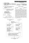
[57]
ABSTRACT
This disclosure is concerned with the use of on-line
Related U.S. Application Data
[63]
simulation of circuit faults during diagnosis to generate
a small part of a complete fault dictionary needed for
diagnosis of the circuit, being adapted for use of a mini
Continuation of Ser. No. 809,101, Jun. 22, 1977, aban
doned, which is a continuation of Ser. No. 583,539,
Jun. 4, 1975, abandoned, which is a continuation of Ser.
computer-based automated test system having only a
small amount of secondary storage; and being adapted
No. 443,853, Feb. 19, 1974, abandoned.
[51]
[52]
U.S. Cl. ................................. .. 371/23; 324/73 R;
[53]
Field of Search ........................... .. 235/302, 302.1;
for an exact match diagnosis with modeled failures, and
a heuristic approach for a partial match of faulty behav
iour that leads to a highly probable diagnosis.
Int. C1.3 ........................................... .. GOIR 31/28
371/20
9 Claims, 6 Drawing Figures
364/200, 900; 324/73 R; 371/23, 15, 20
2a\
2b\
5\
ix
(TESTER)
UUT
:Q
INPUT
STIMULI
lEmITATKJNSl
RFSPON%EIS
PASS UUT
l 4\\
MATCH
.
3'\
COMPARE uuT
"time
cmcurr
'
6.
\
RESPONSES
=H
WITH 600D
CIRCUIT MODEL
9">__
ENTR‘ES
LDCKUP
in mm
DICTIONARY
a‘
__.___
_
‘-°'—£"-——' F'RSIEHNLEEJ
“museum
LE‘EETELJ
15
m?amaoaq
l’ésku‘g?éh
9'\
Fwl-T
SIMULATION
31533151?!)
CIRCUITS
vERIHED
uh?bés
‘o1
2:}
'2
aespgilses
=5 OF UUT WITH
amt-1E0 mus
I3\
PROBABLE
__
.._
14 I~IPART1AL
SF MODELMATCH
Wm,
FAULT
mcmon
U.S. Patent
0a. 14, 1980
Sheet
RESPONSES
1 of3
2
\
SIMULATION
OF
~ FAULT FREE
7\
OF
e000 CIRCUIT
C
% 0F
FAULTS
DETECTED
CIRCUIT
f\
INPUT
STIMULI
EXCITATIONS
(8
cgyéég'g‘g‘ =__1__J> UNDETECTED
FAULTY CIRCUIT
RESPONSES
S‘IMULATION
0F FAULTY
CIRCUITS
=9
RESPONSES
0F FAULTY
CIRCUITS
=9
F‘iglA.
1
2
l:>
|i>
>‘ 21H
r£>———
FAULTS
PARTIAL
FAULT
DICTIONARY
US. Patent
0a. 14, 1980
(w
Sheet 2 of 3
[s
4,228,537
wf2 Jm<O
.Sjdi 29.504
1
4,228,537
METHOD OF AND APPARATUS FOR
AUTOMATIC FAULT DIAGNOSIS OF
ELECTRICAL CIRCUITS EMPLOYING ON-LINE
SIMULATION OF FAULTS IN SUCH CIRCUITS
DURING DIAGNOSIS
2
Comparison of the merits of simulated faults with
actual physical insertions of failures in diagnostic test
development is described, for example, in Digest of
Papers, 1972 International Symposium on Fault-Tolerant
5
This is a continuation application of Ser. No. 809,101,
?led June 22, 1977, which is a continuation of Ser. No.
583,539, ?led June 4, 1975, which is in turn a continua~
Computing, IEEE Computer Society, June 19-21, 1972
(72CH0623-9C), pp. 42-46, and elsewhere. See, also,
Circuits Manufacturing. January, 1974, p. 56, which
describes some of the above problems of automated
fault diagnosis, as well. The various types of faults in
volved, moreover, are described, for example, by Fried
man and Menon, Fault Detection in Digital Circuits,
Prentice-Hall, 1971, commencing on p. 7 and elsewhere.
An object of the present invention is to provide a new
and improved method of and apparatus for automatic
fault diagnosis that shall not be subject to the above
tion of Ser. No. 443,853, ?led Feb. 19, 1974, all of which
are now abandoned.
The present invention relates to methods of and appa
ratus for automatic fault diagnosis employing on-line
simulation of faults in such circuits during diagnosis.
Heretofore, systems have been employed, such as the
CAPABLE type automatic fault isolator marketed by
mentioned and other disadvantages of prior techniques
and systems; but that, to the contrary, requires a limited
prepared partial fault dictionary only, which is supple
Computer Automation, Inc. of California (CAI), Bulle
tin entitled “CAPABLE Product Expansion Note #8”,
mented by on-line fault simulation to improve diagnos
1971, wherein a known circuit is constructed with ex 20 tic resolution and provide a highly adaptive testing
ternally mounted parts, such as integrated circuit units
diagnosis, and without even requiring the physical pres
(IC), and tests are made by introducing short-circuits
ence of a known good circuit to prepare the partial fault
and other failures in such parts to record, in response to
dictionary for diagnosing a unit under test (so-called
known input stimuli to the circuit, the response of such
UUT).
failures in comparison with a good or properly opera 25
A further object is to provide such a novel method
tive circuit, thereby to produce a group of fault re
and apparatus that is particularly suited to digital circuit
sponses corresponding to the speci?c faults-a so-called
fault analysis and that may use a mini computer.
fault “dictionary". Sincethere are a large number of
Another object is to provide a novel adaptive fault
possible or likely faults and a large number of tests
detection and identifying method and system of more
required to catalog the same, such a system must, for
general applicability, as well, that, by combining the
economy of storage and size, use only a partial fault
partial fault dictionary facility with on-line supplemen
dictionary, though some prior manual matching sys
tems, with visual look-up in listings of faults, have been
tal fault simulation, using all information gathered, pro
vides an optimum diagnosis resolution for the particular
otherwise employed, as in the very voluminous printed
fault dictionaries prepared, for example, by Telpar In
corporated of Dallas, Tex., ("User’s Guide To Testaid”,
April, i971). In operation, one tries to match a detected
variance in the behavior of a known good circuit with a
response in the partial fault dictionary in order to diag
nose the failure in the circuit. Because such systems
test program.
35
Still an additional object is not only to diagnosis pre
viously de?ned faults in an algorithmically modeled
manner, but to enable the heuristic simulation of faults,
including multiple faults, not previously modeled.
Other and further objects will be explained hereinaf
employ only a partial fault dictionary, however, it is
ter and are more particularly delineated in the appended
claims. In summary, the invention embraces a method
likely that many different faults can exhibit the same
of on-line simulation to generate a small part of a com
partial fault response; and it is also possible that a wrong
answer can be provided. The system is, moreover, lim
plete fault dictionary needed for diagnosis of, for exam
ple, a given circuit board, permitting the use of a mini
ited by what has been pre-prepared in assembling the 45 computer based automated test system equipped with
partial fault dictionary and is not adaptively operative
only a small amount of secondary storage. Single fail
to perform more sophisticated diagnosis, as of multiple
ures are accurately diagnosed by an exact match with
faults. Additionally, such a system not only involves
modeled failures, while a heuristic approach allows for
pre-preparation of the fault dictionary, but requires an
a partial match of faulty behaviour, leading to a highly
actual operating circuit; and, because of the use of exter 50 probable diagnosis. The method or process underlying
nal mounting of parts, does not lend itself to hybrid and
the invention, from one of its aspects, comprises prepar
high-speed circuit boards and the like.
ing a partial fault dictionary of modeled faults of a cir
Another approach to this problem, has been by way
cuit and storing the same as electrically retrievable
of employing a large computer with massive storage to
responses; subjecting such a circuit to on-line set of
generate the fault dictionary by simulating the re 55 tests; comparing the responses to the tests of the tested
sponses of predetermined faults, and which is then used
circuit with responses of a good circuit to detect varia
during the testing phase by the operator as an aid to his
tions, if existent, from the good circuit responses indica
fault diagnosis. Such service is also offered by said Tel
tive of faults; passing the tested circuit as good in the
par, which employs the IBM Series 360 computer to
generate the fault dictionary. Not only is such an opera
tion disadvantageous in its use of a separate and perhaps
remote large computer, off-line from the testing proce
dures, and with the cumbersome problems of preset and
unadaptive multiple dictionaries necessitated by circuit
absence of such variations; responding to detected vari
ations to extract from the stored partial dictionary a list
of possible faults; simulating on-line the faults from said
test; and comparing the responses of the faulty circuit
under test with the responses of the simulated faults to
effect fault diagnosis of the circuit under test.
boards with slight revisions or modifications, but the 65
As will become apparent, a signi?cant advantage of
operator is required to perform a most laborious, repeti
the invention resides in the fact that by using only a
tive task in fault look-up, with considerable chance of
partial fault dictionary and by employing on-line simu
error.
lation of faulty circuits to generate the responses of such
3
4,228,537
4
circuits, the resolution and comprehensive fault detec
tion capabilities of the full-fault dictionary approach are
obtained, without the necessity of the massive storage
nal input and output, so that application of the external
input values to the network under test will yield the set
requirements normally attendant such approach. As
rectly operating board.
will be described in detail hereinafter, this and other
signi?cant advantages of the invention are preferably
obtained by employing a partial fault dictionary in
which, for each test step, fault classes which are ?rst
detected at that test step, i.e., produce output responses
which vary from those of a good circuit, are grouped in
lists according to their external signatures at that test
step. This is to be contrasted with the previously de
scribed full-fault dictionary approach which stores, for
each modeled fault, the response of the faulty circuit to
the entire set of test steps. In accordance with the inven
In a sequential network, it is usually not possible to
determine test steps except in the context of previous
test steps, since the output values at the circuitry de
pend not only on present inputs but also on a finite
number of past inputs and outputs. Thus we further
tion, when variations from the known responses of a
good circuit are detected during the testing of an actual
circuit, the partial fault dictionary provides a list of
of output values on the external outputs for the cor
de?ne a test program as a ?nite sequence of test steps
designed to distinguish the operation of a correctly
functioning circuit from many possible incorrectly
functioning circuits.
A set of likely failures which a test program is de
signed to detect is called a fault set. As an example, the
most widely used fault set is the set of failures which
causes one node in the logic network to become perma
nently stuck at either the logical 0 or logical 1 level.
These conditions are abbreviated SAO and 5A1, respec
possible faults, and on-line simulation of circuits having
the possible faults is employed to generate the responses 20 tively. The present invention expands the classical fault
sets that are automatically diagnosed, by including
of faulty circuits to the set of tests. These responses may
shorts and several multiple failures. Subsets of a fault
then be compared with the responses of the actual cir
cuit to effect fault diagnosis.
The invention will now be described with reference
to the accompanying drawings.
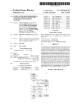
FIG. 1 is a functional or ?ow block diagram of the
set, which are indistinguishable at the externals due to
the topological structure of the logic network, may be
25 collected into an equivalence class. Thus, a fault class is
de?ned as a set of faults that, as observed from the
preparation phase of the technique underlying the in
externals of the network, are equivalent in their behav
iour. For example, in FIG. 1A, Gate A, Pin I stuck at l
vention;
is indistinguishable from Gate A, Pin 2 stuck at O, which
FIGS. 1A, 1B and 1C are partial schematic block
diagrams of illustrative circuits which serve as examples 30 is in turn indistinguishable from Gate B, Pin I stuck at 0,
to explain the underlying diagnostic operation;
FIG. 2 is a similar diagram of the testing and diagnos
tic phase; and
and so on. Using a shorthand notation in which “.” is
read as “pin” and “-” is read as “stuck at," we write:
Fault Class 6: A.l-l A.2-0 13.1-0 B.2-1 C.1-1 C.2-0
Considering the isolating of failures using only infor
FIG. 3 is a schematic diagram of preferred circuits
35 mation at the edge connector pins (externals), fault-find
for practicing the inventive process.
Considering the illustrative problem of digital logic
circuit board testing and the like, in recent years, sev
ing aids generally perform diagnosis by matching the
behaviour of the physical faulty network with a stored
image of the behaviour of certain faults. Acquiring this
image is done by considering some set of likely faults
eral factors have contributed toward rendering the
go/no-go test insufficient and impractical for digital
logic testing and repair. First, the dramatic increase in 40 and simulating their behaviour, given the input stimuli
of the test program. Simulation may be either via physi
the use of medium and large scale integration (MSI and
cal insertion of each failure into the circuit or by soft
LS1) technology has raised the level of circuit complex
ware modeling of the effects of each fault on the logic
ity to a point where manual diagnosis of a faulty logic
network. Since a reasonably complete set of possible
board may require several hours, if not days. At the
same time, high volume production of digital assem 45 faults for a complex board may have several thousand
elements, physical fault insertion is cumbersome at best,
blies, from mini-computers to traffic light controllers,
and usually impractical. Software simulation offers sev
has spotlighted the need to reduce recurring costs of
eral advantages. Since faults are automatically inserted
logic testing. Finally, the cost of an army of skilled
into a model of the network, the effects of changes to
technicians, all intimately familiar with the workings of
either the unit under test or UUT (as in engineering
the logic boards they are testing, has become too high to
changes), or the test program can easily and rapidly be
be practical for all except the lowest volume applica
taken into account. In addition, outputs that should be
tions. Thus there is a great need for automated test
ignored because of noninitialized sequential logic are
equipment which provides fast, accurate diagnosis of
automatically determined and recorded.
faulty behaviour in complex circuits without requiring
The information that is recorded concerning the be
55
highly skilled personnel.
haviour of possible faults is generally stored in a data
The present invention provides such a technique for
automatically diagnosing logic failures by simulating
base previously described as a fault dictionary. The
possible fault mechanisms on-line in accordance with
any of a number of well-known simulation techniques,
extent of these data varies from simply noting at which
test step the fault is detected, to completely recording
all external values for all test steps for each fault. The
as will be described hereinafter.
In order to clarify the discussion of fault diagnosis,
however, several definitions are in order. An external is
any signal made in a logic network which is directly
advantage of the latter is that it most uniquely charac
terizes the behaviour of a faulty circuit, given a particu
lar test program. Unfortunately, this approach is unten
connected to a test ?xture. Thus, an external input is a
able in all but the largest, full-scale, computer-based
signal line directly connecting the input of some logical
65 systems, as it requires great quantities of random access
bulk storage, as before discussed. As an example, con
device in the circuit with the test ?xture, and an exter
sider a circuit for which 2500 fault classes are modeled
nal output similarly connects a logical output to the test
(this would be the size of a typical fault set for a net
system. A test step is a set of values, one for each exter
5
4,228,537
work with about I20 IC packages) and which has 200
externals. A typical test program to detect 98% of the
faults might take 500 to 1000 test steps. To record a full
fault dictionary would thus require more than
SOOX 200x 2500: 2.5 X 108 bits. Although the full fault
dictionary may be reduced without losing any informa
6
stores diagnostic information which is later used in the
automatic fault location program. Since the only inputs
necessary are a network description and a set of input
stimuli, moreover, it is possible to generate a high qual
ity test program for a circuit before it is in production,
and even before a prototype is available.
tion, the amount of data will still be near the same order
The diagnostic ?les, which can be viewed as compris
ing a skeleton fault dictionary, contain essentially the
of magnitude. Methods that abbreviate this fault dictio
nary (as in storing only the failing test step numbers)
have the inherent disadvantage of losing resolution; i.e.,
different faults that could theoretically be distinguished
following information:
(1) for each test step, the fault classes that are ?rst
detected at that step; and
are not, resulting in vague diagnostic messages from the
(2) for each fault class, the external signature of that
fault class at its ?rst failing test step.
An external signature means the set of logical values
system at test time.
To overcome the problems of poor diagnostic resolu
tion on the one hand and excessive storage requirements
on the other, the present invention ?rst stores a small
that are observed on the externals in the presence of a
portion of the fault dictionary composed of the result of
one test step for each possible fault. (In the example
above, this amounts to l><200><2500=5>< 105 bits,
step” is the ?rst test step in the test program sequence
which is reasonable for a disk mass storage device).
good circuit.
particular fault at a given test step. The “?rst failing test
for which, given a particular fault, at least one of the
externals differs in value from that expected on a known
Then, during actual testing, parts of the fault dictionary
Finally, the diagnostic fault information is sorted so
that fault classes with identical ?rst failing test step
numbers and external signatures are grouped together.
which are required for diagnosis of a particular faulty
circuit are generated on-line via simulation. Thus the
full diagnostic resolution inherent in a test program is
Thus, we de?ne a fault group as a set of fault classes that
preserved while at the same time storage requirements 25 have identical behaviour up to and including the ?rst
are kept manageable.
Before explaining in detail the operation of the auto
failing test step.
Consider, for example, the circuit of FIG. 1B, and
matic fault location capabilities of the invention, it is in
that it is given that the input stimulus at test step 2 was
order to mention the preferred software modules de
Ol 10 on nodes 1 through 4. The expected response on
signed to aid in the generation of test programs for 30 nodes 5 to 7 would be 100. However, when simulating
digital networks and to pinpoint failures on these net
the network for any of the faults A.1~0, C.4-0, or B.5-1,
works automatically during testing. There are two basic
above, we will observe the outputs on nodes 5-7 to be
input ?les to the system; namely, a description of the
110. All three of the faults mentioned are detected by
logic network and a set of input stimuli which are to be
the input stimulus at this test step, and in addition they
applied to the network.
35 have the same external signature at this test step, so we
Given these two inputs, the invention uses a digital
say that they are all in the same fault group. ‘
logic simulator automatically to generate the output
Once a test program has been generated and graded
responses of the correctly functioning network for each
for its percentage of fault classes detected, the system is
test step, thus creating a complete test program for the
ready for automatic testing and diagnosis of physical
network. The system then goes on to evaluate the ef? 40 circuits.
cacy of the test program in detecting the likely failure
When a faulty circuit board is encountered during
that might occur on a physical board. In evaluating the
testing, the entire set of results (external input and out
test program, the following types of failures may be
put values) at each test step of the test program is re
considered by the system, depending upon user-selected
corded by the tester for comparison with possible fault
options:
45
mechanisms modeled by the software. In addition, the
(1) inputs and outputs stuck at a logical 0 or I, corre
tester notes the ?rst failing test step number. Using this
sponding to many failures, such as shorts to ground
number, the automatic fault location program of the
or power tracks, or open connections to IC pins;
invention ?nds all fault groups that are detected at this
(2) power loss to an IC, caused by an open or poor
test step. It then compares the output signatures of each
connection on the board;
50 such fault group with the physical output signature of
(3) shorts between adjacent pins on IC’s, caused by
the failing circuit, taking into account any externals
solder splashes on the circuit board art work, or
which may not have been initialized into a known state.
broken wire fragments in a wire-wrap board;
Note that this initial comparison is made only for the
(4) any bridging (short) failure that has been deter
?rst failing test step, since this is the only information
mined as likely to occur by the engineer generating
kept in the skeleton fault dictionary. In most cases, a
the test program, perhaps because of the proximity
match will be found between the physical output signa
of two adjacent tracks on the printed circuit; and
ture and some fault group. If no match is found, how
(5) any open connection, such as a faulty plated
ever, then the behaviour of the physical circuit does not
through hole, which occurs at any location on the
correspond to any of the faults modeled. If, however, a
board, as speci?ed by the test engineer.
match is found, then the faults in that fault group are
The above faults are simulated by inserting them in turn
selected for simulation. These faults are displayed to the
into the same model of the physical circuit that is used
operator as an initial diagnostic message.
to determine the output patterns for the good board. A
in the case of the simple example previously dis
fault is said to be detected if for some test step the exter
cussed (network shown in FIG. 18), this initial message
nal values generated by the faulty network differ from
those values generated by the good circuit.
The system of the invention, in addition to determin
ing whether a test program can detect these failures,
65
would appear as:
A. H)
[-0
4,228,537
7
8
-continued
B. 5-1
EXT6-l
C. 4-0
B. 3-0
F1:
B. 1-0
F2=
F31
t2
0
t3
1
t1
0
t2
o
t3
1
This would be read as: IC A Pin I stuck at 0, connected
; 8 i
;
g :
tolCBPinZandlCDPinl;orICBPin5stuckatl
4
Q
0
1
0
0
or External 6 stuck at l; or IC C Pin 4 stuck at 0, con-
5
l
l
l
1
nected to IC B Pin a and 10 E Pin 1. Note that on the
‘7’ Q, Q)
l
5
External
l
(1
0
t1
o
t2
0
t3
I
:
g i
:
1
0
n
1
1
0
l
l
0
(1) (1)
f
g, (1, ,5
second line, two faults appear. These two faults are 10
collected into one equivalent fault class since they are
,
indistinguishable
at the externals, independent of the
input stimuli that are applied. Other faults indistinguish-
_
_
It;
Dilly slgmlauon vl'm?h [:latches a: reclf'r'gedlfa‘lmy
Fe .aYlo‘lr’ Qwever’ ls t at or F2‘ us.’ t c all t c ass
.
2 is indicated as the cause of circuit failure. Since the
able from. B54 and EXT6-1 are inputs to Gate B stuck l 5 Simulation makes use of every b.it of data available
.
at the
(wmlen B24) and 3:34))‘ These fault? were not
external nodes for comparison with its fault model,
mdlcaited "_1 the example smlply bC‘PauSe an "3pm W91‘
_at
maximum or optimum possible diagnostic resolution is
at 0 failure is extremely rare ‘1n transistor-transistor logic
achievcd A‘ the same time, an exact match between the
(TTL) and slmllar 1081C clrcmts- This 15 because’ "1
physical fault and its computer model guarantees the
reality, it corresponds to two failures occurring on the 20 accuracy of the model and therefore the test program
circuit; namely, an open circuit to the input, and the
evaluation,
input internally shorted t0 Emlmd, 85 shown in FIGAll these operations are performed, for the “average”
1C.
board (50 IC's, 200 test steps), in well under a minute in
Once the possible fault mechanisms have been sethe later-mentioned equipment of the General Radio
lected by a table lock-up, the fault simulator is called 25 Company, assignee of the present invention.
“p011 to verify the faulty behaviour of the physical
It is now in order to describe in more detail the func
circuit against the selected faults. This is done by simu'
"0118' 01 now Operation of the Process in cmmectlon
lating each fault found in the initial lock-up through the
with the steps lnustl'at'ed in FIGS- 1 and 2» ?rst recapltu'
entire test program and comparing the expected outputs
latmg the baffle requirements and adYamages of ‘such
at each step with the actual faulty circuit outputs. Only 30 steps over Pm’r approaches‘ AS Prevlously explamed’
considering the invention as illustratively applied to the
when fault model behaviour matches that of the physi
diagnostic testing of digital circuits and the like, there
cal circuit at each external for each step of the test
are several requirements for the accurate testing and
program is a "veri?ed" diagnosis given.
diagnosis of the digital circuit boards. First, it is neces
Let us suppose, for example, that in the circuit of 35 sary to establish an effective test procedure which con
FIG. 1B, the test program contained the following
sists of the before-delineated input stimuli or excitations,
input stimuli and expected responses:
plus the responses expected from a good network. Se
condly, it is necessary exactly to determine the extent to
which this test program will detect typical fault mecha
nisms on digital circuit boards. This allows test pro
External
grams which do not meet some minimum ?gure of
merit, to be improved. Thirdly, some data to be used
during the diagnosis of bad UUT’s must be prepared.
Finally, an effective process automatically to diagnose
45 bad UUT’s must be established. The data for this pro
cess is, in accordance with the invention, set up during
a preparation mode, illustrated in FIG. 1, while the
process itself is used during the testing mode, FIG. 2.
Now further suppose that the externals recorded by the
tester are as follows:
50
PREPARATION MODE (FIG. 1)
This mode:
External
55
(a) aids in test program generation;
(b) evaluates the quality of the test program for fault
detection and diagnostic resolution;
(c) prepares data for automated diagnosis.
In the past, as before explained, others have carried out
part or parts of this phase either on a very large com
Clearly, the ?rst failing test step is t;. Using the analysis
of the previous section, we see that three fault classes
must be simulated; namely,
F1: A14]
F2: B.5-1 EXT6-1
F3: (3.4-0
Simulation results for the three fault classes above are
shown below:
puter by simulation of the UUT (for example in the
previously mentioned Telpar systems and in the Fair
60 child FAIRSIM system——Fairsim II User’s Manual,
1969) or with a physical known good board on the
tester itself (for example, said “CAPABLE” system).
The previously discussed and other disadvantages of
using a large computer are obvious. Since the computer
65 is very expensive, it is usually not part of a test system.
Thus, the analysis is carried out off-line, resulting in
slow turnaround and large overhead costs. In addition,
the usage of such a system is expensive for small users,
4,228,537
10
even if it is accessible via a telephone line. Finally, such
bers and locations of the faults to be simulated will
a system does not allow a cost effective expansion to
naturally depend upon the particular circuit being
tested, and may be conveniently speci?ed in advance by
the circuit designer. By computing the responses of
test networks with complex large scale integrated cir
cuit (LS1) chips, for which an accurate model may not
be easily generated.
The disadvantages of using a known good board as a
means for preparation are similarly obvious.
First, a known good board (KGB) is often not avail
able or is actually faulty. Second, some inconsistency
between a schematic circuit diagram and the KGB may
exist and not be found during the preparation phase,
resulting in possible bad diagnosis during testing. Third,
faulty circuits at 5, and comparing these responses at 6
with those of the fault-free circuit, the following data
are obtained:
1. the percentage of the simulated faults which are
detected by a given test sequence at 7 (a fault is
detected if the responses of the circuit in the pres
ence of a fault are different from those of a fault
free circuit);
the KBG approach does not indicate unknown or not
. a list of faults which are not detected, at 8; and
necessary determined states (X-state), and initialization
and race problems may go unnoticed during the prepa
. a partial fault dictionary at 9, indicating the re
sponses of a faulty circuit for the ?rst test in which
ration phase. Again this may cause problems during
testing. Fourth, manual intervention is required, making
the procedure slow and error-prone. Fifth, the evalua
the response differs from that of the good circuit
tion of the test program is based on physical failure
?rst failing test, to facilitate a look-up and match in
(i.e. the ?rst failing test). In addition, this partial
fault dictionary is indexed by the number of the
the second phase of the process, later explained.
insertion. The previously-mentioned manual process 20
Turning now, to FIG. 2, (circuit testing and diagno
involved is also replete with problems. For example, the
sis) a sequence of programmed input stimuli is applied at
before-described approach taken by CAI, supra, re
quires that lC’s be removed from the KGB and inserted
1 to a unit under test (UUT) 2a, and the electrical re
sponses of this circuit are recorded for each successive
into a special test ?xture. This test ?xture is in turn
connected to the KGB at the missing IC socket via a 25 input stimulus in the sequence at 2b. The particular
input stimuli corresponding to the set of tests to be
applied to the circuit under test are also dependent upon
the particular type of circuit being tested, and may also
pled logic (ECL) and Schottky-transistor-transistor
be prepared in advanced in accordance with well
logic (TTL), may not be analyzed by this technique.
Sixth, the KGB approach cannot be extended to pro 30 known techniques. Subsequently, this set of recorded
responses is compared at 4’ with the set of responses
vide an automatic test generation capability.
expected from a fault-free circuit established at 3 in
To overcome the problems of these earlier appro
FIG. 1. If the above two responses match, then the
aches, the process of the present invention simulates
circuit is said to pass the test, as indicated at 5'. If, on the
complex digital circuits on a minicomputer, which is an
integral part of the test system, as later described. In 35 other hand, there is a variation or difference between
these responses, the test number at which a difference
addition to exhibiting none of the shortcomings of pre
cable that may be several feet long. Thus, boards with
several types of high-speed logic, such as emitter cou
vious approaches, this method implicitly facilitates the
analysis of complex failure mechanisms, such as bridg
dictionary 9 of FIG. 1. At this point, a match is sought
ing faults, including shorts.
between the response of the electrical circuit and com
Turning, thus, to the speci?c functional or flow
charts of FIGS. 1 and 2, there is shown the particular
implementation in which on-line simulation of faulty
circuit behaviour is used automatically to test and diag
nose digital logic circuits.
?rst occurs is used as an index at 6' into the partial fault
puted responses of modeled faulty circuits (in the dictio
nary). If no match is found between the modeled faulty
networks and the UUT response, then an automatic
diagnosis is not made at 7'. However, for the usual case
in which a match is found, all modeled faulty circuits
The two parts of the process by which circuits are 45 which match the response of the electrical circuit at the
automatically diagnosed consists of the previously de
?rst failing test are automatically selected for simulation
scribed:
1. preparation of data which partially characterizes
the behaviour of a large number of different faults
at 8'.
The responses at ll] of these modeled circuits are now
computed by simulation at 9' and compared with the
on circuits of the type which are to be tested, as 50 responses of the UUT at 11. A veri?ed diagnosis is
shown in FIG. 1; and
. comparison of the electrical responses of a physical
circuit under test with the computed responses of
given when the behaviour of the UUT exactly matches
the behaviour of some modeled fault on every output
and for all tests, as computed by the on-line simulation
corresponding digital circuit models, which are
at 12. If there is no exact match between the behaviour
simulated on-line at the time the circuit is tested, as 55 of any modeled fault and that of the UUT, then a proba
ble diagnosis is given at 13 for that fault which matches
illustrated in FIG. 2.
the UUT behaviour for the largest number of steps in
Referring to FIG. 1, (the preparation of diagnostic
the test sequence. In other words, a probable diagnosis
data), the behaviour of a digital circuit under the appli
is given for that fault which ?rst mismatches UUT
cation of a programmed set of input stimuli 1 is simu
lated at 2, and the expected responses of a fault-free 60 behaviour at the highest test step number. The diagnosis
is given as a printout or display of the appropriate mod
circuit are thereby computed at 3. In addition, the effect
of a large number of different likely faults on this circuit
eled fault(s) which matched UUT behaviour, along
is determined by simulating the behaviour of the circuit
with an indication of whether the match was partial or
complete, as at 14 and 15, respectively.
plained, the types of faults simulated include shorts 65 While the implementation of the process, once de
in the presence of each fault, as at 4. As before ex
between different logic signals, as well as those faults
which cause any lead in a digital logic circuit to become
permanently ?xed at one logic level. The types, num
scribed as above, will probably readily be evident to one
skilled in this and the related computer art, and while it
is desired not to clutter the description with details of
11
4,228,537
12
may be useful to indicate sufficient circuit and computer
is found, as at 8', FIG. 2, then the on-line fault simula
tion process is invoked by simulating at 9', FIG. 2, to
operational speci?es to make evident the preferred con
determine if the simulation of faulty circuits 4, FIG. 1,
?gurations and operation.
matches the actual responses of the faulty UUT. The
simulation function 4 of FIG. 1, as before indicated,
well-known circuitry and programming techniques, it
While the diagrams of FIGS. 1 and 2 functionally
describe the underlying operation, FIG. 3 illustrates
preferred circuit elements for effecting these functions
may be effected in the same manners described in
of a given test, as conventionally sequenced by a mini
connection with the simulation process 2. This may be
effected by putting in one or more faults, and comput
ing the responses of the circuit given such fault or
faults. Thus the present invention does not require the
presence of an actual good circuit as in the before
computer 22, such as the Digital Equipment Corpora
mentioned prior systems.
tion PDP-BE computer, which loads the stimulus data
into the stimulus pattern register 24, such as a latch-type
storage register. The output responses of the UUT 2a
This process has computed the responses of circuits
corresponding to the "list" of faults at 8', FIG. 2; and
these responses are then compared at 11, FIG. 2, with
the stored responses of the faulty UUT 2b. This is a
similar process to the mechanism previously described
in connection with the comparator 4'. Branch 12 pro
vides an indication of a complete match of all responses
between a simulated fault and the actual faulty UUT 2b,
providing a diagnosis of the fault.
in connection with a mini-computer. The unit under test
(UUT) 2a is shown provided with inputs from signal
driver ampli?ers 20, 20', 20", etc. that receive the data
are compared by respective comparators 26, 26', 26",
etc. with reference level(s) 28, to determine the logical
states of the outputs of the UUT, the aggregate of
which is the response pattern. This pattern is stored in a
response pattern register 30 and thence read into the
computer 22; this being the storage function 2b of FIG.
2, resulting from functional stages 1 and 20 thereof.
The thusly stored UUT responses at 2b (FIG. 2) are
compared with the responses of a good circuit 3 (FIGS.
In the event that some tests match the model but
some other tests do not match, the heuristic approach is
invoked to identify a highly probable fault diagnosis.
This may, for example, be effected by counting the
1 and 2), as well known, within the PDP-SE or similar
number of matched tests in computer registers; the
modeled fault with the highest count, being indicated as
computer 22 in the basic instruction capability thereof,
as described in the said Digital Equipment Corporation
handbooks, “Introduction To Programming” and
“PDP-SE & PUP-8M Sanall Computer Handbook”,
(1969-72). For deriving the responses at 3, the simula
the probable fault. The handling of such problems by
this heuristic technique has been found to be successful
in over 90% of the cases in which faulty circuit behav
iour was caused by failures other than those explicitly
modeled. The technique employs the same strategy as
outlined above but allows for only a partial match be
tween the simulated network outputs and actual faulty
behaviour. Success of this method hinges on the obser
vation that multiple failures most often make themselves
tion function 2 of FIG. 1 may be attained, for example,
by using the “logical” and, the “logical complement"
and the “mask” instructions of said computer, as de
scribed in said handbooks, representing the logical con
nections and function of the circuit 3 that is to be tested.
Such simulation processes are more fully described in
“Logic Automated Stimulus and Response”, User’s
Guide Version DIB, Digitest Inc., Dallas, Tex., 1973.
As another example, a preferred simulation technique
known one at a time in a test program, and that the ?rst
failing fault signature on the physical board usually will
correspond to the fault signature of one of the faults.
Similarly, a non-modeled short will usually manifest
at 2, FIG. 1 (and at 4, later described), may be of the
type described in the thesis of one of the inventors
itself as a temporary “stuck" at 0 on one of the shorted
herein, Haas, entitled Bridging Fault Analysis In Digital
outputs.
Circuits, Massachusetts Institute of Technology, Febru
In this case of an imperfect match with any modeled
ary, I974, Chapter 5. See, also, Second Workshop On
Fault Detection & Diagnosis In Digital Systems, Le
high University, Dec. 6-8, 1971, p. 115-117, on, for
example, for further simulation techniques. Also, Sec
tion 3.4 of “Fault Diagnosis of Digital Systems". Chang
et al, Wiley-Interscience, 1970. Other fault simulation
fault, the automatic fault location program will indicate
a probable fault location. This will correspond to the
fault classes that match the operation of the physical
circuit for the greatest number of test steps through the
program.
Returning to FIG. 2 and the look-up process at 6', if
techniques which may be employed are disclosed in 50 no match with dictionary entries is effected, as at 7',
U.S. Pat. No. 3,702,011 to Armstrong, issued Oct. 31,
then this process is terminated without identi?cation of
I972; U.S. Pat. No. 3,780,277 to Armstrong, issued Dec.
the fault at this point.
18, 1973; and U.S. Pat. No. 3,715,573 to Vogelsberg,
Since all the circuit details are not considered neces
issued Feb. 6, 1973.
sary
to an understanding of the invention and its opera
55
tion, reference is made to the Operating Instructions,
As before explained, if there is a match, an indicator,
Type 1792A and 179213 Logic Test Systems, Jan. 21,
such as a green lamp, indicates “pass” at 5'; i.e. a good
UUT is present. If there is no match, diagnosis is
1974 (Form l792-0I02F), the CAPS Operation Manual
required of the fault, and the diagnostic process is
fo the Type 1792 Logic Test Systems, October, 1973
initiated. The step in the test program at which the ?rst
(Form 1792-0105E) and Parts Lists and Diagrams of
Type 1792A and 1792B Logic Test Systems, Septem
failing response pattern at 30 (FIG. 3) is detected, as
before explained, is used as the entry or index element
ber, 1973 (Form l792-0I04-A), of the assignee of the
into the partial fault dictionary 9 (FIGS. 1 and 2).
Knowing this number, the computer searches the elec
trically retrievable stored partial fault dictionary (func
tionally indicated at 6' in FIG. 2), by its searching
routine, as described in said handbooks, to locate and
extract the "list" of possible faults corresponding to the
matched modeled responses stored at 9. If such a “list”
present application, General Radio Company of Con
cord, Mass.
65
Further modi?cations will occur to those skilled in
this art, and such are considered to fall within the spirit
and scope of the invention as de?ned in the appended
claims.
What is claimed is:
13
4,228,537
14
responses of the circuit under test with the responses of
a good circuit to detect variations which are indicative
of faults; means for selecting from a stored partial fault
l. A method of automatic fault diagnosis of an electri
cal circuit under test comprising applying a set of tests
to the circuit under test; comparing the responses of the
circuit under test with the responses of a good circuit to
detect variations which are indicative of faults; select
dictionary of modeled circuit faults a list of possible
circuit faults which are capable of producing at least
one of said variations; means for simulating on-line
circuits having at least one of the faults from said list;
means for generating the responses of the simulated
ing from a stored partial fault dictionary of modeled
circuit faults a list of possible circuit faults which are
capable of producing at least one of said variations;
simulating on-line circuits having at least one of the
faults from said list; generating the responses of the
simulated circuits to the set of tests; and comparing the
responses of the simulated circuits with the responses of
the circuit under test to effect fault diagnosis.
2. A method as claimed in claim 1 and in which said
circuits to said set of tests; and means for comparing the
responses of the simulated circuits with the responses of
the circuit under test to effect fault diagnosis.
6. Electrical circuit fault diagnosis apparatus as
claimed in claim 5 and in which the last-named compar
ing means comprises means responsive to the matching
of all the responses of the circuit under test for all tests
to those of a simulated circuit to verify the fault diagno
last-named comparing step comprises matching all the
responses of the circuit under test for all tests of said set
to those of a simulated circuit to verify the fault diagno
sis.
7. Electrical circuit fault diagnosis apparatus as
claimed in claim 5 and in which the last-named compar
last-named comparing step comprises effecting a partial 20 ing means comprises means responsive to a partial
matching of some of the responses of the circuit under
match of the responses of the circuit under test for some
test for some tests to corresponding responses of a simu
tests to corresponding responses of a simulated circuit
lated circuit to indicate probable fault location.
to indicate probable fault location.
8. Electrical circuit fault diagnosis apparatus as
4. A method as claimed in claim 1, wherein said par
tial fault dictionary is prepared by simulating in re 25 claimed in claim 5 comprising means for storing the
responses of the circuit under test and means for storing
sponse to the set of tests fault-free circuit responses;
the responses of the good circuit.
simulating in response to the same set of tests modeled
9. Electrical circuit fault diagnosis apparatus as
faulty circuit responses; comparing the fault-free and
claimed in claim 5 in which the ?rst~mentioned means
faulty circuit responses in order to detect variations;
81$.
3. A method as claimed in claim 1 and in which said
and generating from said comparing, said partial fault
dictionary by grouping all modeled circuit faults which
comprises stimulus pattern register means for storing
produce the same variations for a particular one of the
tests of said set.
5. Electrical circuit fault diagnosis apparatus for a
circuit under test comprising means for applying a set of 35
tests to the circuit under test; means for comparing the
the stimulus pattern register means for applying the
input tests to the circuit under test; and response pattern
register means for storing the circuit responses to said
input tests of said set; signal driver means connected to
45
55
65
input tests.
l
$
‘
l
i