1
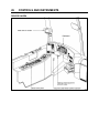
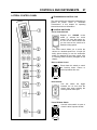
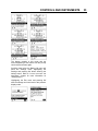
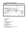
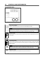
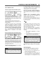
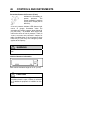
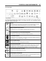
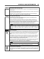
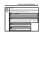
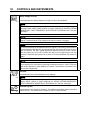
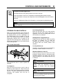
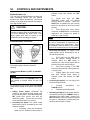
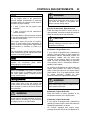
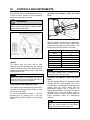
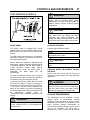
CONTROLS AND INSTRUMENTS
23
UTILITY COMPARTMENT KEY
KEYS
Four different key models are provided with the
vehicle. They are used as described below.
FRONT ENTRANCE DOOR LOCK KEY
UTILITY COMPARTMENT KEY
23344
This key locks or unlocks the utility compartment
and the utility drawers on the dashboard.
IGNITION SWITCH KEY
FRONT ENTRANCE DOOR LOCK KEY
23057
Use this key to lock or unlock the entrance door
from outside. It is also possible to lock or unlock
the entrance door using the entrance door
locking switch, the keyless entry system or the
remote entry transmitter.
EXTERIOR COMPARTMENTS KEY
IGNITION SWITCH KEY
23056
Turn the ignition key counterclockwise to the
ACC position to activate the electrical circuits.
To start the engine, turn the key clockwise to the
START position, and then release it. The key will
set back to the ON position.
CAUTION
EXTERIOR COMPARTMENTS KEY
23302
Use this key to lock or unlock any exterior
compartment door, including the fuel tank filling
access doors, the baggage compartment doors
and electrical/service compartment doors. It is
also possible to lock or unlock the baggage
compartment from the inside by means of the
central locking system switch located on the L.H.
dashboard panel.
NOTE
For your protection against theft:
o
o
Record the key numbers and keep this
information in a safe place. Do not keep
these records inside vehicle.
It is also advisable to deposit a duplicate
of each key in a safe place, so they can
be obtained without difficulty in case of an
emergency or loss.
When the vehicle is parked overnight or for an
extended period of time, the battery master
switch should be set to the OFF position.
NOTE
When the battery master switch is set to the
OFF position, all electrical supply from the
batteries is cut off, with the exception of
battery equalizer check module, MCM ignition
and
power
supply,
TCM
power
(Transmission), coolant heater electronic
timer coolant heater and water re-circulating
pump, pro-driver, power-verter, keyless entry
system and fire alarm.
REMOTE ENTRY TRANSMITTER
Up to four hand held (electronic key)
transmitters can control electronic door lock
system.
REMOTE ENTRY TRANSMITTER
23383
24
CONTROLS AND INSTRUMENTS
To lock the entrance door and the baggage
compartment doors simultaneously and arm
the intrusion protection and anti-theft
system:
o
Press LOCK
on the transmitter once.
NOTE
NOTE
For complete information concerning the
Remote Keyless Entry & Anti-theft Alarm
System, refer to the document included in
your vehicle “publication box”.
IGNITION SWITCH
The intrusion protection and anti-theft system
will be set after a 30 seconds delay.
ACC.
OFF
ON START
To confirm that the entrance door and
baggage compartment doors have been
locked and that the intrusion protection and
anti-theft system is armed:
o
again within five seconds of
Press LOCK
the first lock. The front and rear side
markers will flash once if the doors have
locked. If the entrance door or one of the
baggage compartment doors is open, a door
ajar signal prevents arming of the system.
To unlock the entrance door:
o
on the transmitter. This
Press UNLOCK
will unlock the door and disarm the intrusion
protection and anti-theft system.
To unlock the baggage compartment doors:
o
a second time within five
Press UNLOCK
seconds of the first unlock.
To set off the personal security alarm:
o
button on any
Press the red PANIC
transmitter. The horn will sound and the
marker lights will flash for a maximum of
three minutes.
To deactivate the personal security alarm:
o
button again on
Press the red PANIC
any transmitter or turn the ignition key ON.
NOTE
The remote entry features will not function
when the ignition is in the ON or ACC.
position.
For additional information, refer to "OTHER
FEATURES" chapter.
IGNITION SWITCH POSITIONS
06354
The ignition switch is located on the lower left
side of the dashboard. It has four positions:
Off
In the OFF position, ignition cannot take place.
The key can be removed when in this position.
The electrical circuits are not activated when the
switch is in this position. Only the accessories
connected directly to the batteries can be
activated. Maintain the switch in this position
when parked overnight or for an extended
period.
NOTE
The main battery relay is activated when the
hazard flashers are activated, even if the key
is in the OFF position.
Accessories
To operate the accessories only, turn the ignition
key counterclockwise to the “ACC” position. The
key cannot be removed in this position.
The electrical circuits are activated when the
switch is in this position or when the hazard
flashers are activated.
The features enabled when the key is in the
ACC position are all those linked directly to the
battery plus the exterior temperature display, the
radio or entertainment system, exterior and
interior lighting.
On
To place ignition switch to ON, turn the key
clockwise to the first position. The key cannot be
removed in this position.
CONTROLS AND INSTRUMENTS
The electrical circuits activated when the switch
is in the ACC position plus the transmission,
engine and accessories, ABS system, air dryer
heater, wipers, dashboard cluster gauges and
buzzers are activated when the key is in this
position. Do not leave the key in this position
unless the engine is running.
Start
Turn the key clockwise to the second position
and release as soon as the engine starts. The
key will return to the ON position. If the engine
did not start, return the ignition key to the OFF
position before trying to restart the engine.
The ignition switch is equipped with a starter
protection which inhibits turning the key to the
START position if the key has not previously
been turned to the OFF position.
CAUTION
To avoid overheating the starter, do not
engage the starter for more than 15 seconds
at a time. Allow the starter to cool before
trying to restart the engine
The features activated when the engine is
running are all those described above plus the
HVAC system and daytime running lights. The
optional ether cold-start system is automatically
deactivated once the engine runs.
25
26
CONTROLS AND INSTRUMENTS
DRIVER’S AREA
18675
CONTROLS AND INSTRUMENTS
LATERAL CONTROL PANEL
27
c TRANSMISSION CONTROL PAD
The control pad for the automatic transmission is
located as shown. Refer to "Automatic
Transmission" in this chapter for operating
instructions and more information.
d CONTROL SWITCHES
Cruise Control Switch
Depress the CRUISE rocker
switch to activate the cruise
control. This turns the system on.
A LED on the switch shows that
you can now set the vehicle at a
desired cruising speed.
06701
The cruise control allows you to cruise the
vehicle at a desired speed over 18 mph (30
km/h) without having to use the accelerator
pedal. For operation of the cruise control, refer
to “Steering Wheel Controls” paragraph in this
chapter.
Back-up Alarm Cancel
Press down this switch to cancel
the back-up alarm. Return to
normal operation after use.
06311
Horn Selector
Use this switch the toggle
between the air horn and the
electric horn when pressing the
steering wheel center pad.
06700
Power Window Switch
Use this rocker switch to open or
close the driver’s power window.
18676
06338
28
CONTROLS AND INSTRUMENTS
NOTE
CAUTION
Close power window when parked or leaving
the coach unattended.
Outside Rear View Mirror Heat (Optional)
Press this rocker switch to clear
fog, frost or thin ice from outside
mirror.
If the mirror assemblies on your vehicle do not
include convex mirrors, only one mirror control
knob will be installed for both mirrors. To
operate, turn knob to the left for L.H. mirror
adjustments and to the right for R.H. mirror
adjustments, then use the joystick control to
adjust the selected mirror’s viewing angle.
f g h LEVEL LOW SYSTEM
06261
Central Locking System
This system enables locking all
baggage compartment doors by
pressing the switch forward. To
unlock, press the switch rearward.
06266
NOTE
Service compartment doors are not linked to
the central locking system.
NOTE
Doors must be locked using the key first; they
can then be unlocked or locked using the
central locking system.
e MIRROR CONTROLS
Convex
Flat
MIRROR CONTROLS
06374
Turn left pointer knob counterclockwise for flat
mirror adjustments and to the right for convex
mirror adjustments, then use the joystick control
to adjust the selected mirror’s viewing angle.
Adjust the right outside mirror similarly but by
using the right side control.
When driving, the conventional air leveling
system of the vehicle controls the height at three
points: the front, the left rear and the right rear.
Your vehicle is equipped with a suspension
system that consists of air springs (pressurized
air bellows) located near each wheel. The
amount of air in each air spring (and thus the
vehicle height) is controlled by automatic
leveling valves that operate between the chassis
and the axles of the vehicle.
The three leveling valves are located as follows:
one at the front which controls the amount of air
in both front air springs, one at the left rear
which controls the left rear corner of the vehicle
and one at the right rear which controls the right
rear corner of the vehicle. During normal driving,
these valves work automatically to maintain the
chassis at the proper level above the axles,
indifferent of road conditions or vehicle weight.
When parked, and ONLY when parked, the level
of the vehicle can be manually adjusted within
the range of travel of the air springs. Thus, if the
vehicle is parked on uneven ground, the manual
override leveling system can be used to level the
chassis of the vehicle. With the ignition ON
(engine running or not), turn the selector switch
located on L.H. side control panel to the area of
the vehicle requiring leveling, then press the
height control switch accordingly (up or down) to
inflate or deflate the selected set of air springs.
The front position raises or lowers the front only
and does not tilt the vehicle to its sides. Each
rear position raises or lowers its respective side,
therefore, the rear positions can be used to tilt
the vehicle to one side or the other, or they can
CONTROLS AND INSTRUMENTS
29
be used to raise or lower the rear of the vehicle.
When leveling vehicle, it is often necessary to
run the engine in order to get an adequate air
supply.
NOTE
It is always better to first level the rear of the
vehicle (right to left) before raising or lowering
the front. After adjusting the rear, watch the
level indicator as you adjust the front. If the
level shows that the vehicle is starting to tilt to
either side, then stop adjusting the front as
one of the air springs has come to the end of
its travel range.
After manual leveling, turn OFF the engine. The
vehicle will stay in the leveled position (the air is
"locked" in the air springs) as long as there are
no air leaks. The vehicle will hold this position
for several days. When engine is restarted and
air pressure is adequate, the vehicle will
automatically level itself for driving conditions.
WARNING
Do not drive the vehicle with the level low
selector switch in any position other than
OFF, as this may render the vehicle unsafe
and uncontrollable. If this is the case, the
Level Low warning telltale light in dashboard
will flash, reminding you that the selector is
not in the OFF position.
CONTROL VALVES
12224
j TAG AXLE CONTROL VALVE
Lift the tag axle by pushing the lever forward.
Pulling the lever back will lower (load) the tag
axle. Refer to "OTHER FEATURES" chapter for
additional information.
WARNING
Do not drive vehicle with tag axle raised when
speed is exceeding 12 mph (20 km/h).
k TRAILER AIR SUPPLY CONTROL VALVE
(Optional)
The trailer air braking system
is supplied by pushing this
control valve.
12225
NOTE
If, for any reason, you wish to start the engine
without moving vehicle (to warm up engine for
instance) while keeping the vehicle in the
manually leveled position, place selector
switch in any position except OFF. When
ignition switch is turned to the OFF position,
reset the Level Low selector switch to the
OFF position.
i PARKING BRAKES CONTROL VALVE
Spring-loaded parking brakes are applied by
pulling up the control valve knob and protector
assembly. Lift the safety cover and push down to
release brakes. Refer to “SAFETY FEATURES AND
EQUIPMENT" chapter.
06485
10. Utility Compartment
11. 12-volt DC Power Outlet
12. Ashtray
13. Cigarette Lighter
30
CONTROLS AND INSTRUMENTS
(10) (11) UTILITY COMPARTMENT & 12-VOLT
DC POWER OUTLET
TIRE PRESSURE
(TPMS)
The lockable free space utility compartment also
includes a 12-volt appliance socket.
This system is a sensing device designed to
identify and display tire operating data and
activate an alert or warning when pressure or
temperature irregularities are detected.
(12) ASHTRAY
To open the ashtray, push slightly on the cover’s
side. The ashtray can be removed for cleaning
by pulling it out.
WARNING
MONITORING
SYSTEM
NOTE
It is the responsibility of the driver to react
promptly and with discretion to alerts and
warnings. Abnormal tire inflation pressures
should be corrected at the earliest opportunity.
To prevent a fire, never put paper or plastic
wrappers in the ashtray. Empty ashtray often.
(13) CIGARETTE LIGHTER
Push lighter in to activate. When ready to use, it
will spring out automatically. Replace lighter in
non-activated position. The cigarette lighter
socket can be used to power 12-volt appliances
(eg. flashlight, vacuum cleaner). The maximum
power consumption allowed for appliances
plugged in this socket is 130 watts. Make sure
the appliances are equipped with suitable plugs
that will not damage the socket.
TPMS Display
NOTE
The cigarette lighter can still be used after the
ignition key has been removed.
DIAGNOSTIC
RECEPTACLE
TPMS DISPLAY
DATA
READER
(DDR)
To facilitate troubleshooting of the DDEC, WT
and ABS systems and to obtain data logged in
the MCM (Motor Control Module) memory, a
Diagnostic Data Reader (DDR) (not supplied)
can be connected through the DDR receptacle.
A user's manual is supplied with the optional
DDR.
The DDR receptacle is located inside the
footwell, on the upper left side wall.
The TPMS display knows where the sensors are
located. It receives the raw temperature and
pressure readings from the TPMS receiver, it
reads several signals from the vehicle and does
the calculation required to generate the various
screens.
When no readings have been received for a tire
location or when the received data correspond
to a parameter range defined as unavailable,
then the reading is considered as not available
and appears as two dash lines “_ _“.
The TPMS display is initially configured to define
how many axles and running tires are present
on the vehicle. For current Prevost vehicle
models, there are two axle / tire configurations.
These configurations are:
Config 1: Axle 1 (Front) Two tires, Axle 2
(Drive) 4 tires, Axle 3 (Tag) 2 tires.
Config 2: Axle 1 (Front) Two tires, Axle 2
(Drive) 2 tires (super Singles), Axle 3 (Tag) 2
tires.
The TPMS display is also configured with
several other parameters, including threshold
levels for the alarms.
CONTROLS AND INSTRUMENTS
The TPMS display power supply turns OFF
when the ignition key is switched OFF.
Operation
The system will monitor all vehicle tires (6 or 8)
plus the spare tire when a spare is supplied.
NOTE
Some vehicle models do not come with a spare
tire.
There are two configurations of vehicle tires to
be supported. One configuration (the most
common) consists of 8 tires total: two tires on
the front axle, 4 tires on the drive axle and 2 tires
on tag axle. All screen figures shown in this
document relates to this vehicle configuration.
The second tire configuration consist of 6 tires
total: 2 tires on the front axle, 2 tires on the drive
axle (super single tires) and 2 tires on the tag
axle. The vehicle tire configuration is selected
with a parameter (Refer to “SAFETY FEATURES
AND EQUIPMENT” chapter for more information).
When the display is configured for 6 tires, the
drive axle tires appears as one large tire on both
side instead of twin tires as illustrated in this
document and there is one reading appearing on
each side instead of two as illustrated in this
document.
Start-up
When turning the ignition switch to ON, the
following screen appears on the TPMS Display.
Dash lines are displayed meaning that no
pressure data have been received by the
display.
--- ---
PSI
--
-- --SPARE TIRE: - PRESSURE DEVIATIONS
TARGET PRESSURES
GAUGE PRESSURES
--
PSI
--
-- --1
-- 1
-SPARE TIRE: - PRESSURE DEVIATIONS
TARGET PRESSURES
GAUGE PRESSURES
As illustrated, the pressure readings will appear
replacing the dash lines as the TPMS display
starts to receive pressure data from the TPMS
receiver. It can take 1 minute to get all pressure
readings updated since the sensors transmit at a
one minute interval.
The user can flip through the menus.
31
Pre-Trip Check
When one of the preconditions defined to start
the pre-trip check is met, the TPM display enters
into a pre-trip check routine and the screen
shown below appears. The preconditions to
initiate the pre-trip are: Park brake removed Or
No activity on the display menu keys for a
defined time (Key pressed timeout). After a pretrip, the display is in a “drive” mode with bottom
menu replaced by the alarm status. The display
remains in this mode until one of the following
occurs: A menu key is touched while the park
brake is applied, or the park brake does a
transition from released to park brake applied.
--- --1
PSI
--
-- 1
-SPARE TIRE: - -
PRE-TRIP CHECK IN PROGRESS
During the pre-trip check, the pressure readings
for the different wheels become all available.
The pre-trip check ends, either when: the
pressure readings have been received for all
running wheels or the pre-trip check maximum
time has elapsed. It was selected to provide
sufficient time for all wheel sensors to wake-up
and send a first reading.
The pre-trip check is aborted and the bottom
menu reappears if the park brake was active
and the user press one of the menu keys.
Upon completion of the pre-trip check, the
TPMS display will come up with one of the
following screens:
32
CONTROLS AND INSTRUMENTS
The switching to temperature works when the
bottom message indicates either: Tire Pressure
OK, Pressure Not Optimal non flashing or not all
tires monitored non flashing. When the switch is
done to temperature readings, the bottom
portion of the screen is not affected and still
shows the status message.
NOTE
A rectangle around each pressure/temperature
reading of the tires that have an issue is blinking
to draw the attention to the defective tires.
In the case of multiple errors at the same time,
the highest priority error is displayed at the
bottom. “Flat Tire” has the highest priority
followed by “High Temperature”, “Not all tires
monitored” and “Tire pressure not Optimal”.
To get the driver’s attention to the alarms, the
bottom section of the screen where the alarm
message appears will blink to reverse contrast
at the following rate: 0.7sec normal contrast, 0.3
sec reverse contrast. Pressing any key will
acknowledge the alarms that are considered as
non critical and stop the blinking of these alarms
message for the remaining of the trip. The non
critical alarms are: “Pressure not optimal” and
“Not all tires monitored”. The “flat tires” and “high
temperature” alarms are critical and will keep
blinking even when a key is pressed. If a
different alarm occurs, blinking will start again.
The
blinking
rectangle
around
the
pressure/temperature readings is not impacted
by the acknowledgement and keeps blinking
until the error condition disappears.
The spare tire does not contribute to alarms and
so never blinks.
On the road, the TPMS display shows one of the
5 previous screens.
In the event of a temperature alarm, the display
switches automatically to temperature readings.
The driver can also press any of the menu keys
to momentary switch the display to temperature
readings. In this case, the temperature reading
appears for 15 seconds and the display returns
to pressure.
The switching to temperature by pressing a key
does not take place if there is an
acknowledgeable alarm active, since in this case
pressing the key does acknowledge the alarm.
The switching to temperature does not take
place either if there is an alarm of Temperature
or Flat Tire.
High temperature is not likely to occur during
the pre-trip.
The pressure and temperature readings are
continuously updated with the displayed
readings of the wheel having issues blinking.
The bottom line message is automatically
updated to the highest priority alarm prevailing.
There is a hysteresis on the alarm levels to
assure that the error conditions do not flicker ON
and OFF.
On the occurrence of an alarm, a beep will
sound. The alarm beep could be turned OFF in
the alarm settings menu.
Spare tire:
The spare tire is monitored but it is not taken into
account when setting the bottom alarm
messages. This is to prevent unnecessary
alarms that would otherwise occur, if for
example, the spare tire is removed from a
vehicle.
The user will have the possibility to check the
pressure of the spare tire by accessing the
TPMS display menu. For vehicles that have no
spare tires, the title “spare tire:“ will still appear
on the screens but the pressure will remain with
two dash lines at all time.
Post Trip Operation
When parking the vehicle (park brake applied),
the TPMS display keep the drive mode display
active. The driver can press any keys to get the
bottom lines showing the status information
replaced with the menus.
The pressure readings are still displayed and
updated as new readings are received and the
readings are blinking if not within the optimum
pressure range.
From this point the user can scroll through the
menus to get more detailed information and
inflate/deflate the tires to bring them back to their
optimum target pressures. Scrolling through
these menus is also available prior to departure.
CONTROLS AND INSTRUMENTS
The display remains in this mode with the
menus appearing at the bottom until the pre-trip
check sequence starts again.
Scrolling down below the Battery life menu will
show the Settings menu. Highlighting the
Settings and pressing OK allows entering the
settings menu. Refer to “SAFETY FEATURES AND
EQUIPMENT” chapter for more information on
“Settings Menu”.
Highlighting the Exit menu and pressing OK
exits the settings and come back to the pressure
display mode.
33
34
CONTROLS AND INSTRUMENTS
DASHBOARD
DASHBOARD
1.
L. H. DASHBOARD PANEL
2.
MCD KEYPAD
3.
TELLTALE PANEL
4.
GAUGES
5.
VEHICLE CLEARANCE INFORMATION
6.
R.H. DASHBOARD PANEL
7.
HVAC CONTROL UNIT
8.
BRIGHTNESS CONTROL
9.
MESSAGE CENTER DISPLAY (MCD)
10.
IGNITION SWITCH
11.
TIRE PRESSURE MONITORING SYSTEM DISPLAY (TPMS)
12.
ADJUSTABLE AIR REGISTERS
06698
CONTROLS AND INSTRUMENTS
35
CONTROL SWITCHES
High quality laser-engraved switches are used to control many of the features of the coach. Many switches
have an embedded witness LED to inform the driver at a glance which features are active. Some switches'
LED will turn OFF after a short while when the engine is running. This is normal and is designed to reduce
glare when driving. The functions still operate even if the LED is OFF. If the switches are still ON when the
engine is turned OFF, the LEDs will illuminate to warn the driver to turn them OFF.
L. H. DASHBOARD PANEL
The L.H. dashboard panel includes driver-exclusive
controls, ether start control switch, ignition switch and an
adjustable air register for the driver.
L. H. DASHBOARD PANEL
06711
Headlights and Exterior Lighting
06254
OFF position – Daytime running lights only.
Press this rocker switch to turn on the following lights:
First position – Front parking lights, taillights, clearance lights, marker lights, license plate
light.
Second position (push down fully) - the headlights, the controls and instrument lights and
all lights from the first position.
NOTE
Daytime running lights will be automatically cancelled when the exterior lighting switch
is fully depressed (second position).
Fog Lights (Optional)
Optional halogen fog lights provide better visibility in fog and precipitation. They improve
close range visibility and provide added safety.
NOTE
06255
Some states and provinces restrict the use of fog lights. Verify local state or provincial
regulations before using.
36
CONTROLS AND INSTRUMENTS
Hazard Warning Flashers
Press the rocker switch to make all turn signal lights flash at once. The dashboard telltale
lights will flash when the hazard warning flashers are ON.
CAUTION
06256
Do not use the hazard flashers for an extended period of time unless necessary
because the electrical circuits are activated when the hazard switch is depressed.
Upper Windshield Wipers (Optional)
Press the rocker switch to the first position to activate the upper wipers intermittently.
Press to the second position for continuous operation of the upper wipers.
CAUTION
06257
To avoid damaging the wiper blades or scratching the windshield, do not operate the
wipers when the windshield is dry. Also, loosen frozen wipers before operating.
NOTE
Lower windshield wipers are activated using the multi-function lever. Refer to
paragraph: “Steering Column Controls” in this chapter.
Upper Windshield Washer (optional) & Headlights Washer
Press this rocker switch upwards to spray the upper windshields with washer fluid.
Windshield wipers will automatically come on and stop a few seconds after releasing the
switch.
Momentarily press this rocker switch downwards to spray the headlights washer fluid. Each
pressing of this switch produces 2 successive jets.
06615
CAUTION
Do not operate the washer mechanism while the washer fluid reservoirs are empty.
This may damage the washer fluid pumps.
NOTE
Lower windshield wipers are activated using the multi-function lever. Refer to
paragraph: “Steering Column Controls” in this chapter.
Low Docking
Press the rocker switch to reduce cornering and docking lights intensity.
06486
CONTROLS AND INSTRUMENTS
37
Docking / Cornering
Press this rocker switch upwards (DOCKING) to illuminate the cornering and docking lights.
Press this rocker switch rearwards (CORNERING) to illuminate the cornering lights when
signaling a left or right turn.
06337
Manual Regeneration / Stop Regeneration
Manual Regeneration
DPF Regeneration Lamp
The «DPF Regeneration Lamp» illuminates to notify the driver of the need and urgency
of a manual stationary regeneration.
06660
If stationary regeneration is not performed, this telltale will blink, indicating that a
stationary regeneration is required immediately. If stationary regeneration is still not
performed, “engine power derate and shutdown” sequence may occur.
To initiate a stationary regeneration:
• Park the vehicle in a clear area, vehicle speed must be 0 mph (0km/h);
• Engine must be on normal idle and fully warmed up (coolant temperature above
140°F/60°C);
• Apply service brakes and set the transmission to the neutral “N” position.
• While maintaining the service brakes applied, apply parking brake, release it and then
apply parking brake once again (this sequence is required to enable the stationary
regeneration);
• Press and hold for 5 seconds the top-most switch position to initiate a stationary
regeneration;
The regeneration will begin. Turn off the air conditioning to reduce engine load. The
engine idling speed will increase to 1600 rpm. Once the regeneration is completed, the
engine speed will return to normal idle.
Stop Regeneration
Inhibit Regeneration Lamp
The «Inhibit Regeneration Lamp» illuminates to indicate the system’s acknowledgement
of regeneration inhibit request and to remind the driver that regenerations have been or
will be inhibited.
Press down to cancel a regeneration that is in progress or to inhibit a pending
regeneration. Use this function to move the vehicle to a safe parking place. Releasing the
parking brakes will also cancel the regeneration.
38
CONTROLS AND INSTRUMENTS
NOTE
STATIONARY REGENERATION
This process requires the vehicle to be parked while the driver or a maintenance
technician initiates the regeneration process.
NOTE
To initiate a stationary regeneration while the Engine Protection Shutdown sequence
has already started, you must press and hold both the «Engine Stop Override» switch
and the «Manual Regeneration» switch at the same time until the regeneration starts.
Once started, the regeneration may last for only a few minutes and engine may shut
down again. Repeat the operation as required until the stationary regeneration can be
completed.
CAUTION
Before initiating stationary regeneration or using the inhibit regeneration function, read
carefully and understand paragraph “Detroit Diesel Exhaust Aftertreatment System” in
Chapter 4 “OTHER FEATURES” for complete information concerning regeneration
precautions. Ignoring them could result in extensive damage and/or serious personal
injury.
Fast Idle
For extended idling periods, run the engine at fast idle. Press down the rocker switch to
engage fast idle. This increases the engine speed to approximately 1,000 rpm. Return to
normal idle before driving or when stopping engine.
CAUTION
06264
Even if normally the engine will return to normal idle and remain there if the parking
brake is applied and/or transmission is placed in neutral (N), it is safer to first press
down the rocker switch to run the engine at normal idle before engaging the
transmission.
CAUTION
Return the engine to normal idle before shutting the engine OFF.
Engine Brake / Transmission Retarder
Use this switch to select between the transmission retarder and the engine brake when
using the vehicle speed retarding device switches on the steering wheel. Both systems
cannot be in function at the same time. This rocker switch can be found on the dashboard,
only if the vehicle is equipped with both systems. Refer to "Transmission Retarder” heading
in this chapter. Refer also to "Transmission Retarder” & “Engine Brake” in “OTHER
FEATURES” chapter.
06703
CONTROLS AND INSTRUMENTS
39
Engine Stop Override
Press this switch then release to override the emergency engine shutdown protection.
Engine emergency shutdown will be turned OFF for 30 seconds. This procedure can be
repeated if done before the 30 seconds are up.
06265
CAUTION
Use sparingly and in order to move the vehicle to a safe parking place only. Excessive
use can cause severe engine damage.
DDEC Diagnostic Request
With the engine at idle or OFF and with the ignition switch in the ON position, press and
release the Engine Stop Override rocker switch. Active codes will be flashed on the “ Stop
Engine “ and inactive codes on the “ Check Engine “ telltale lights alternately. Refer to
Appendix D “DDEC VI Diagnostic Codes”.
Telltale Light Test
Press down and maintain this switch at least 2 seconds to illuminate the telltale light panel.
The telltale panel audible alarm will sound. Perform this test to verify indicator light and
telltale panel audible alarm functionality.
06263
Ether Start Control (Optional)
Activates the engine cold starting aid.
chapter.
Refer to "STARTING
CAUTION
06237
Excessive use may result in severe engine damage.
AND STOPPING PROCEDURES"
40
CONTROLS AND INSTRUMENTS
R.H. DASHBOARD PANEL
R.H. DASHBOARD PANEL
06562
Driver's Area Lighting
Press the rocker switch to turn on the driver's overhead light as needed.
NOTE
06244
The entrance overhead light and the stepwell lights turn on with the entrance door
opening and turn off with door closing. If the entrance door is left opened, these lights
will be turned off automatically if the batteries voltage drops below 24.0 volts.
Back-up Camera
Press this switch to activate the back-up camera monitor when the transmission is not in the
reverse gear.
06314
Front Entrance Door
Press this switch forward to lock the entrance door from the inside. To unlock the entrance
door from the inside and disarm the intrusion protection and anti-theft system, press the
switch rearward.
NOTE
06313
When the alarm system is armed, unlocking the entrance door from the inside by
sliding its lock lever will not disarm the alarm system. The alarm will sound.
Brightness Control
Adjusts the brightness of the dashboard instruments and switches.
06565
CONTROLS AND INSTRUMENTS
To prevent battery run-down, the central A/C
and heating systems will not operate if the
charging system is not working properly.
HVAC CONTROL UNITS
Vehicles equipped with small HVAC system
CONTROL UNIT FOR SMALL HVAC SYSTEM
41
22286
The temperature control in the driver’s area is
provided directly by the driver section of the
HVAC control unit.
Using the Up/Down type switch sets the fan
speed and the speed chosen is illustrated on the
window display.
In addition to the driver’s unit, the small HVAC
system also includes an auxiliary unit which
uses the temperature control of the driver
section of the control unit. The R.H. section of
the control unit AUX. FAN enables to actuate the
auxiliary unit and to regulate its fan speed. Using
the < > type switch sets the fan speed and the
speed chosen is illustrated on the window
display.
Vehicles equipped with central HVAC system
When the A/C system is running, park at least 4
feet (1,5 m) from other vehicles or buildings to
allow sufficient air flow through the condenser
core.
Separate driver and passenger heating,
ventilation and air conditioning controls are
located on this control unit. To operate, the
vehicle’s engine must be running.
The driver section and the passenger section of
the control unit may be turned ON by pressing
the following button:
06372
Also, the driver section of the control unit turns
on automatically at starting of the engine and
uses the settings that were kept in memory
before turning off of the system.
The A/C compressor starts automatically
when the two following conditions are
satisfied:
1. The outside temperature is above
32°F (0°C).
2.
The passenger's area temperature has
reached 7°F (4°C) under the set point.
NOTE
CONTROL UNIT FOR CENTRAL HVAC SYSTEM
22276
The vehicle is slightly pressurized by the central
HVAC system to prevent dust and moisture from
entering. Air flow and controls divide the vehicle
into two areas: driver’s area with defroster and
passenger's (cabin) area.
Fresh air is fed in each area and has a separate
return air and discharge air duct.
NOTE
To operate the air conditioning system when
stationary, run engine at fast idle. When the
system is running, keep windows and door
closed.
Upon starting, if the outside temperature is
above 32°F (0°C) and then drops below 32°F
(0°C), the compressor will keep running up to
a temperature of 15°F (-9°C) to prevent
condensation from forming on the windows.
All parameters set before turning the system
OFF will be kept in memory for the next power
ON.
HVAC Air Registers
The HVAC system has registers to control air
flow around the driver’s and navigator’s area.
• Three are located on the dashboard, two on
the R.H. side and one on the left.
• Two more registers are located near the
steering wheel column, under the dashboard.
These registers are not adjustable but may
42
CONTROLS AND INSTRUMENTS
be electrically open or closed by means of
the HVAC control panel.
• Three auxiliary unit registers are located
behind the driver (with small HVAC system
only).
• For the navigator, two adjustable registers
are located near the entrance door, at bottom
of first lateral window.
Heating Mode Indicator
This red LED illuminates when
system is heating.
22135
Cooling Mode Indicator
This green LED illuminates when the
system is cooling (when the
compressor clutch is engaged).
22134
NOTE
DASHBOARD AIR REGISTER
22287
Both Heating Mode and Cooling Mode
indicator LED can illuminate simultaneously.
During winter, if the outside temperature is
above 32°F (0°C), the A/C compressor may
start for dehumidification purposes to prevent
condensation from forming on the windows.
During summer, the Heating Mode may
activate to regulate inside temperature.
Fan Speed
NAVIGATOR’S AIR REGISTER & FAN SPEED SELECTOR
Navigator fan speed switch
Upon turning on of the HVAC control unit, both
right and left windshield defogging/defrosting
fans speed is set according to the driver section
settings of the control unit. The navigator can
afterwards, use this switch to increase or
decrease
the
right
windshield
defogging/defrosting fan speed as needed.
Navigator air registers
On small HVAC system, these registers are part
of the auxiliary unit. Use the auxiliary unit fan
speed switch on the R.H. portion of the control
unit (AUX. FAN) to regulate the fan speed.
Doing so will also reduce air from the three
registers located behind the driver.
On vehicles equipped with the Central HVAC
system, these registers are supplied in air by the
passenger’s (cabin) unit.
22135
This switch controls both right and
left windshields defogging/defrosting
fans speed. Increase speed by
pressing on the upper portion of the
button, decrease by pressing on the
lower portion.
Auxiliary Unit Fan Speed (With Small HVAC
System Only)
Use this switch to increase or
decrease the auxiliary unit fan speed
by pressing on the right or left
22289
portion of the button.
Recirculate
Closes or opens the driver's and
passenger's section fresh air damper.
22138
A red LED in the top right corner of the button
illuminates when air is recirculating. Use for
faster section heating.
This feature is automatically cancelled when
defogging is activated.
CONTROLS AND INSTRUMENTS
Driver's section temperature setting
The temperature displayed on the
driver section of the control unit is the
temperature set point.
22132
Windshield Defogger/Defroster
Upon pressing this button, the
dashboard damper sends air only to
the lower windshield. The fans are
turned on to maximum speed, the
fresh air damper opens completely
(REC off) and the driver set point is
increased to 4°F (2°C) over the
passenger's section set point.
To increase the temperature set
point, press on the "+" sign, to
decrease the temperature set point,
press on the " - " sign. Temperature
range is between 60°F and 82°F
(16°C to 28°C). On the driver section
only, asking for a temperature set
point of 82°F (28°C) will keep the
coolant valve open.
In case of interior temperature
sender unit failure, the coolant valve
will remain open and three lines “---“
will be displayed.
WARNING
Warm temperatures may cause drowsiness
and affect alertness while driving. Keep the
temperature comfortable but not to high.
22139
22132
To increase or decrease the
temperature set point, press on the
"+" or the " - " sign. Pressing these
buttons will flash the displayed set
point and the word "SET" will
highlight. Temperature range is
between 60°F and 82°F (16°C to
28°C).
In case of interior temperature
sender unit failure, the coolant valve
will remain open and three lines “---“
will be displayed.
NOTE
Upon starting of the vehicle, when the ambient
temperature is very cold and so is the inside of
the vehicle, the HVAC control unit will permit a
temperature overshoot up to 3° over the
passenger’s area set point to help warming up
of the area.
The dashboard damper sends air only
to the lower windshield when
activated. The footwell damper is
closed also but the fans speed can be
reduced or increased.
Panel and Footwell
The dashboard damper sends air to
the panel vents and footwell.
22137
Panel
22136
Passenger's (cabin) section temperature
setting (with Central HVAC System)
The temperature displayed on the
passenger section of the control unit
is the actual temperature in the
passenger's area.
43
Air is sent to panel vents. The foot
damper is closed.
Temperature Degree Selector
Toggles the HVAV control unit
temperature units between Fahrenheit
and Celsius. The driver’s section must
be on. Also toggles the outside
22133 temperature units displayed on the
telltale panel.
44
CONTROLS AND INSTRUMENTS
CLUSTER
CLUSTER
06710
The cluster incorporates the Message Center
Display, the Telltale Panel, the Gauges and
Vehicle Clearance Information.
Engine Oil Pressure
Indicates engine oil pressure.
The normal reading should be
between 50 and 70 psi (345 480 kPa) at 55 mph (90 km/h).
MESSAGE CENTER DISPLAY (MCD)
06229
06399
This standard feature gathers, stores and
displays important information about the
vehicle’s operation on a display screen on the
lower left portion of the cluster. Refer to
Message Center Display in “OTHER FEATURES”
chapter for a description of how to set up and
operate the Message Center Display.
A low oil pressure indicator LED (bottom right
corner of gauge) illuminates when the MCM
decides oil pressure is too low. In such a case,
the MCM will start to power down the engine
until finally shutting it off as explained under
“STOP Engine” telltale light, in this chapter.
An audible alert signal also informs the driver of
low oil pressure. Refer to “SAFETY FEATURES AND
EQUIPMENT” chapter for table of audible alerts.
GAUGES
NOTE
Do not refer to dashboard instruments during
adjustment procedures. Use only calibrated
gauges.
CAUTION
Loss of oil pressure may cause severe engine
damage. If low oil pressure LED illuminates,
park the vehicle safely and stop the engine
immediately. Request service assistance.
CONTROLS AND INSTRUMENTS
Engine Coolant Temperature
Indicates
the
operating
temperature of the engine
coolant.
The normal reading
should be between 190°F and
222°F (88°C to 106°C).
06231
A high coolant temperature indicator LED
(bottom right corner of gauge) illuminates when
the coolant temperature rises above 223oF
(106oC). An audible alert signal also informs the
driver of this condition.
Voltmeter (24-Volt System)
Indicates the condition of
the
24-volt
electrical
system. With the engine
running, the normal reading
should be between 26.5
and 28.0 volts.
06224
Fuel Level
Indicates the amount of fuel
remaining in the fuel tank.
The engine protection system will start power
down. Refer to “SAFETY FEATURES AND
EQUIPMENT” chapter for table of audible alerts.
06225
Turbo Boost Pressure
Indicates turbo boost pressure in
psi. Reading depends on engine
rpm and load conditions.
06230
Tachometer
Indicates the operating
speed of the engine in
hundreds of revolutions per
minute (rpm x 100). The
tachometer serves as a
guide for gear shifting and
Speedometer
Indicates the vehicle speed
in miles per hour (mph) and
kilometers per hour (km/h).
06222
The digital odometer records the distance
traveled in miles or in kilometers (units are
driver selectable).
A telltale light illuminates
when about 12 US gallons
(45 liters) of fuel remain in
the fuel tank.
CAUTION
Operating the vehicle when the reading is
below 1/8 full is not recommended.
Accessories Air Pressure
Indicates the accessories
air system pressure. The
normal operating pressure
is from 95 to 125 psi (655 to
860 kPa).
06226
Primary System Air Pressure (Rear)
Indicates the primary air
system
pressure.
The
normal operating pressure
is from 95 to 125 psi (655 to
860 kPa).
06221
helps to prevent engine over-speeding when
driving downhill with the JACOBS engine brake
operating. The maximum allowed engine speed
is 2,450 rpm.
45
06228
A low air pressure indicator LED (bottom right
corner of gauge) illuminates when the primary
air system pressure drops below 66 psi (455
kPa). An audible alert signal also informs the
driver of low air pressure. Refer to “SAFETY
FEATURES AND EQUIPMENT” chapter for table of
audible alerts. If the air pressure drops below
40 psi (276 kPa), the emergency brake applies
at full capacity.
WARNING
Do not drive the coach when air pressure is
low.
46
CONTROLS AND INSTRUMENTS
Secondary System Air Pressure (Front)
Indicates the secondary air
system
pressure.
The
normal operating pressure
is from 95 to 125 psi (655 to
860 kPa).
06227
A low air pressure indicator LED (bottom right
corner of gauge) illuminates when the
secondary air system pressure drops below 66
psi (455 kPa). An audible alert signal also
informs the driver of low air pressure. Refer to
“SAFETY FEATURES AND EQUIPMENT” chapter for
table of audible alerts. If the air pressure drops
below 40 psi (276 kPa), the emergency brake
applies at full capacity.
WARNING
Do not drive the coach when air pressure is
low.
Vehicle Clearance Information
00012
Safe vehicle clearance height is 12’10" (3.9 m).
CAUTION
Vehicle clearance is higher when the
ventilation hatch is open, Hi-Buoy is selected
or if additional equipment is installed on the
roof.
CONTROLS AND INSTRUMENTS
47
TELLTALE PANEL
TELLTALE PANEL
06652
The telltale lights illuminates during 5 seconds at the start of every ignition cycle as a light bulb check.
Some telltale lights described below appear on the telltale panel only if the corresponding optional
equipment is installed on the vehicle.
Slide-Out
Illuminates when one or both slide-outs are partially or fully extended. Blinks to indicate
that an error condition has been detected (refer to “OTHER FEATURES” chapter).
06559
Baggage Compartment Door Unlocked
Illuminates when one or more baggage compartment doors are unlocked.
06387
Flat Tire (with optional Tire Pressure Monitoring System)
Illuminates when a tire pressure is 25% below the target tire pressure.
06694
Fuel Filter/Water Separator
Illuminates when accumulated water in the optional fuel filter/water separator needs to be
drained. Refer to “CARE AND MAINTENANCE” chapter.
06291
Level Low System Indicator
Illuminates when the vehicle leveling system is activated.
06297
06272
Antilock Brake System (ABS)
Illuminates when the ABS is not available or when the ABS is malfunctioning. Since the
ABS system does not operate at less than 4 mph (7 km/h), the indicator will remain
illuminated until the coach reaches that speed. Refer to "OTHER FEATURES" chapter.
Driver Controlled Differential Lock (DCDL)
Illuminates when the differential action is locked
06272
Trailer Emergency / Parking brake
06591
Illuminates when the trailer emergency/parking brake is unexpectedly applied as when the
vehicle is moving and a parking brake air line rupture happens.
48
CONTROLS AND INSTRUMENTS
Trailer Antilock Brake System (ABS)
Illuminates when the trailer ABS is malfunctioning.
06585
ATC
Automatic Traction Control (ATC)
Illuminates when the automatic traction control system intervenes to prevent excess wheel
spin during acceleration.
Left Turn Signal
Flashes when the left turn signals are activated. Signal right and left turns by operating the
multi-function lever. See “Steering Column Controls” in this chapter.
06290
NOTE
The directional signals are automatically activated when the vehicle is backing up.
Emergency Window Open
Illuminates when an emergency window is open or unlocked.
06572
Baggage Compartment Door Ajar
Illuminates when one or more baggage compartment doors are ajar.
06573
Engine Door Ajar
Illuminates when the engine compartment door is ajar.
06592
High Exhaust System Temperature Lamp (HEST Lamp)
Illuminates to notify the driver of potentially hazardous exhaust gas temperature at the DPF
outlet.
WARNING
06654
06655
During regeneration, exhaust temperature may reach up to 1200°F (650°C) at the
diesel particulate filter. When parking the vehicle, if this warning light is illuminating,
make sure that the DPF outlet diffuser is away from people or any flammable
materials, vapors or structures.
Malfunction Indicator Lamp (MIL)
Indicates a failure of an Emission Control device. May illuminate at the same time as the
“Check Engine” Amber Warning Lamp. The lamp will go out when the fault is inactive.
Vehicle can be driven to end of shift. Call for service.
CONTROLS AND INSTRUMENTS
06656
49
Check Engine (Amber Warning Lamp)
Indicates a minor fault detected by DDEC VI system. This warning lamp is illuminated for
all active faults.
The warning lamp will remain ON until the malfunction has been corrected. Vehicle can be
driven to end of shift. Call for service.
A diagnostic code will be stored in the memory and the lamp can be used to identify the
problem. Refer to Appendix D under "DDEC VI Diagnostic Codes".
06657
STOP Engine (Red Stop Lamp)
Illuminates when a potential engine damaging fault is detected. Immediately park the
coach in a safe place and stop the engine.
Flashes when Engine Protection Shutdown occurs. When a problem is detected, the
engine power will automatically begin to decrease gradually, followed by full shutdown
after 30 seconds. The Engine Protection Shutdown may be bypassed by using the “Engine
Stop Override" switch on the L.H. lower control panel. Use only in order to move the
vehicle to a safe parking place and then shutdown the engine. Call for service.
NOTE
Once the engine is stopped, it cannot be restarted until the problem has been
corrected. A diagnostic code will be stored in memory. The STOP engine indicator can
be used to identify the problem. Refer to Appendix D under "DDEC VI Diagnostic
Codes".
06282
Check Transmission
When the "CHECK TRANS" indicator is illuminated and the shift selector emits short beeps
for 8 seconds, the transmission control module (TCM) is restricting transmission shifting
because special or abnormal conditions are detected. The control pad display will be
blank.
If this happens, drive the coach to the next available service center to receive assistance.
The TCM will not respond to shift selector requests since operating limitations are being
placed on the transmission (i.e. upshifts and downshifts may be restricted). Direction
changes and shifts to and from neutral (N) will not occur.
Any time the CHECK TRANS telltale light illuminates, the transmission control module will
register a diagnostic code. It may be identified on the display (Allison & ZF-Astronic
transmission) or by using a diagnostic tool. Refer to Appendix C.
NOTE
The CHECK TRANS indicator may also illuminate when starting the engine in
extremely cold weather. Refer to "Starting and Stopping Procedures".
Transmission fluid Temperature
Illuminates when the transmission fluid temperature is too high. An audible alert signal also
informs the driver of this condition. Disengage the retarder to allow the oil temperature to
cool down.
06292
50
CONTROLS AND INSTRUMENTS
Windshield Washer or Headlights Washer Fluid Low
Illuminates when the windshield washer or the headlight washer fluid level is low. The
washer fluid containers are located inside the front service compartment.
066001
WARNING
Do not drive without sufficient washer fluid.
06286
Fuel Level Low
Illuminates when approximately 12 US gallons (45 liters) of fuel remains in the tank. After
the light comes ON, the remaining fuel will provide no more than 60 miles (100 km) of
travel. Do not exceed this distance.
NOTE
Refuel as soon as possible.
06284
Cruise Control Enabled
Illuminates when cruise control is enabled.
Right Turn Signal
Flashes when the right turn signals are activated. Signal right and left turns by operating
the multi-function lever. See “STEERING COLUMN CONTROLS” in this chapter.
06289
NOTE
The directional signals are automatically activated when the vehicle is backing up.
06696
Freezing Conditions
The word ICE is momentarily displayed when the temperature is in the range between 2°C
and 1°C (35°F to 34°F), when the road is most slippery. The rest of the time, the exterior
temperature is displayed at this location.
Emergency/Parking Brake
06303
Illuminates when the emergency/parking brake is applied. The control valve is located on
the L.H. control panel. An audible alert will sound if ignition is turned to OFF and the
parking brake is not engaged.
Stoplights ON
06305
Illuminates when rear stoplights illuminate. This occurs when service brake, engine
retarder or transmission retarder is applied and when the parking brakes are applied with
engine running.
High Beam ON
06300
Illuminates when high beams are selected. High and low beams are selected by operating
the multi-function lever. Refer to “Steering Column Controls” heading in this chapter.
CONTROLS AND INSTRUMENTS
51
Fire Detected
Illuminates if a fire is detected in the engine compartment while the vehicle is on the road.
An audible alert informs the driver when a fire is detected. In case of fire detection when
parked (parking brake applied, engine running or not), the electric horn is activated to alert
the driver. Refer to “SAFETY FEATURES AND EQUIPMENT” chapter.
06288
WARNING
In case of a fire, stop the vehicle immediately, stop the engine and evacuate the vehicle.
NOTE
It is possible to cancel an alarm while on the road. To do so, stop the vehicle. Cycle the
ignition between the ON and OFF position and then start the vehicle normally. This can
be done on a temporary basis when a false alarm is activated by a defective fire
detector. The driver can go on without being annoyed by the alarm.
NOTE
To stop the electric horn alarm when parked, cycle the ignition
between the ON and OFF position twice within 3 seconds.
NOTE
For extinguisher's location, refer to “Safety Features And
Equipment” chapter.
52
CONTROLS AND INSTRUMENTS
Battery Voltage Incorrect
06588
Illuminates when the battery voltage is too high, too low or not equalized.
NOTE
To identify the battery problem (too high, too low or not equalized voltage), using the
message center display (MCD), perform a system diagnostic by selecting SYSTEM
DIAGNOSTIC, FAULT DIAGNOSTIC & ELECTRICAL SYSTEM and see the fault
messages.
NOTE
The high/low battery voltage indicator will illuminate for a few seconds after the
engine is started because of the voltage drop when the starter is engaged.
NOTE
To prevent discharge of the batteries when the engine in not running, some functions
are automatically switched off if the batteries voltage drops below 24.0 volts for more
than 30 seconds. The "BAT" telltale light blinks while this protection mode is active.
Set the ignition key to the OFF position and then turn the ignition key to the ON
position to reactivate the functions for a period of 30 seconds before they switch off
again.
NOTE
If the battery equalizer indicator illuminates, make sure that the battery equalizer
circuit breakers are reset before requesting breakdown assistance. Wait 15 minutes
after setting breakers to allow batteries to equalize. The breakers are located in the
main power compartment.
Alternator
Illuminates when one of the alternators is not charging.
06586
NOTE
To identify which alternator is defective (1=lower, 2=upper), using the message center
display (MCD), perform a system diagnostic by selecting SYSTEM DIAGNOSTIC,
FAULT DIAGNOSTIC & ELECTRICAL SYSTEM and see the fault messages.
06271
Retracted Tag Axle
Illuminates when the tag axle is retracted. The telltale panel audible alarm will sound to
warn the driver. The control valve is located on the L.H. lateral console.
CONTROLS AND INSTRUMENTS
53
A/C System Pressure High Or Low
Illuminates when the A/C system pressure is too low or too high.
06658
If the A/C pressure is too low, the compressor clutch disengages and the fan stops.
If the A/C pressure is too high, the compressor clutch is disengaged, but the fan remains
activated.
Refer to the Maintenance Manual for information on control panel troubleshooting mode.
NOTE
When outside temperature is low or high, it is possible and normal for that telltale
light to come ON.
STEERING COLUMN CONTROLS
Many of the most frequently used controls are
conveniently placed on the steering column or
the steering wheel, just like a passenger car.
The Multi-function lever is located on the left
side of the steering wheel while the optional
transmission retarder lever is located on the
right side of the steering wheel. Switches for the
electric horn and the air horn are located directly
on the steering wheel.
MULTI-FUNCTION LEVER
Lane Change Signal (2)
Move the lever part way to the catch position
and hold until the lane change maneuver is
completed. The lever will spring back into the
OFF position once released.
Headlight Beam Toggle Switch (3)
Toggle between high and low beams by pulling
the lever up towards you. To flash the
headlights, pull the lever up halfway. The lever
will spring back into normal position once
released.
Courtesy Blinkers (4)
Clearance and parking lights can be flashed by
pressing the button located on the lever tip.
Windshield Washer Control (5)
Push the external ring at the end of the lever
toward the steering column to activate the lower
windshield washers. The wipers come ON and
continue wiping for a few seconds after the ring
is released.
MULTI-FUNCTION LEVER
23133
The multi-function lever is used to operate the
following:
Turn Signal (1)
Move the lever all the way up until it locks in
position to signal a right turn. Move the lever all
the way down until it locks in position to signal a
left turn. The lever automatically returns to the
horizontal OFF position once the turn is
completed.
WARNING
Before using the windshield washers in cold
weather, heat the windshield with the
defroster to prevent icing and reduced
visibility.
CAUTION
To avoid damaging the pump mechanism, do
not use the windshield washer when the fluid
level is very low or empty.
54
CONTROLS AND INSTRUMENTS
Windshield Wipers (6)
Turn the lever counterclockwise to activate the
lower windshield wipers. The first position
activates the wipers intermittently. The second
position is the slow speed and the third position
is for high speed wiping.
CAUTION
To avoid scratching the windshield, do not
operate the wipers when the windshield is dry.
To avoid damaging the wiper motor, free
wiper blades that may be frozen to the
windshield before operating the wipers.
reached. Press and release the SET
button.
2.
Press
and
hold the RES
(RESUME) button until the desired
cruising speed is reached. When the
RES button is released, the new cruising
speed will be stored in the cruise control
memory.
3.
When driving with cruise control,
each time the RES button is momentarily
depressed, the cruising set speed is
raised by 1 mph (2 km/h).
NOTE
When driving with cruise control, the vehicle
can still be accelerated by depressing the
accelerator pedal in the usual manner. Once
the accelerator pedal is released, the vehicle
will return to the previously set cruising speed.
STEERING WHEEL CONTROLS
• Decreasing Set Speed. The vehicle cruise
speed setting can be decreased by one of
the following methods.
STEERING WHEEL CONTROLS
14069
The steering wheel controls include the
following:
Cruise Control Buttons (1) SET, (2) CANCEL,
(3) RES
NOTE
The CRUISE switch and RESUME button do
not operate at speeds below 20 mph (32
km/h).
To operate the cruise control, press the CRUISE
rocker switch located on the lateral control panel
first.
• Setting Coach Speed. Accelerate the
vehicle to the desired cruising speed using
the accelerator pedal. Press and release the
SET button then remove foot from the
accelerator pedal. This will set the vehicle
cruise speed and store it in memory.
• Increasing Set Speed. The vehicle cruise
speed setting can be increased by one of the
following methods.
1.
Accelerate using the accelerator
pedal until the desired cruising speed is
1.
Press and hold the SET button
until the desired cruising speed is
reached. When the SET button is
released, the new cruising speed will be
stored in the cruise control memory.
2.
Each brief pressing of the SET
button will decrease set cruising speed by
1 mph (2 km/h).
3.
Slightly apply the service brake
and when desired cruise speed is
reached, press and release the SET
button.
• Canceling Set Speed. You can cancel the
preset cruising speed by.
1.
Pressing
CANCEL button.
2.
momentarily
the
Depressing the brake pedal.
• Resuming Set Speed. If the preset speed is
cancelled by pressing the CANCEL button or
depressing the brake pedal, pressing the
RES (RESUME) button will restore the speed
set prior to cancellation, providing that your
speed is above 9 mph (15 km/h).
CONTROLS AND INSTRUMENTS
NOTE
When driving downhill with the cruise control
on, the engine brake or the transmission
retarder engage automatically (if previously
activated) when the selected cruise speed is
exceeded by approximately :
• 7 km/h (4 mph) with the engine brake
activated;
• 1 km/h (0.6 mph) with the transmission
retarder activated.
The engine brake or the transmission retarder
is then disengaged when speed has returned
to selected cruise speed.
The engine brake will provide low braking
power or high braking power depending on
which of the two steering wheel engine brake
control buttons is activated; (1) LOW or (2)
HIGH.
The transmission retarder maximum braking
level is determined by the retarder hand lever
position on the steering wheel.
NOTE
To avoid sudden vehicle hesitation, slightly
depress the accelerator pedal before
disengaging the cruise control.
NOTE
When the CRUISE rocker switch is released,
the cruise control is completely shut off and
the cruise speed setting is erased from the
cruise control memory.
IMPORTANT NOTE
If the engine was stopped and the CRUISE
rocker switch was in the ON position, the
rocker switch must be reset by turning it OFF
then ON again in order for the cruise control to
be reactivated.
55
WARNING
Do not put the transmission in the neutral (N)
position while driving with cruise control. This
may cause the engine to over-speed and
result in a loss of driving control.
(4) & (8) Left Sunshade; Right Sunshade
Press and hold the button to lower the left or
right sunshade. Press twice rapidly and hold the
button to raise the left or right sunshade.
CAUTION
Do not attempt to raise or lower these shades
manually. Damage to electric motor or roller
mechanism could result.
(5) Retarder / Engine Brake Low
If your vehicle is equipped with a transmission
retarder, press this button to simply enable the
transmission retarder. Afterwards, operate the
transmission retarder with the hand lever
mounted on the steering wheel or the brake
pedal. For more information about the operation
of this system, refer to “Transmission Retarder”
heading in this chapter.
On vehicles equipped with an engine brake, the
engine brake provides two levels of braking
power. Press this button for low engine braking
power (about 70 % of full braking power). Refer
to “OTHER FEATURES” chapter for more
information about the engine brake operation.
WARNING
Engine brake must be used on dry road only.
Never use the engine brake on slippery roads;
loss of control could result.
(6) Retarder / Engine Brake OFF
WARNING
Do not use the cruise control when driving
speed must be constantly adjusted, such as in
heavy traffic or on winding, icy, snow-covered
or slippery roads, or on gravel roads.
Press this button to cancel operation of the
transmission retarder or the engine brake.
(7) Retarder / Engine Brake High
If your vehicle is equipped with a transmission
retarder, this button has the same effect than the
Retarder/Engine Brake Low button.
On vehicles equipped with engine brake,
pressing this button will permit full application of
56
CONTROLS AND INSTRUMENTS
engine brake (100% of braking power). Refer to
“OTHER FEATURES” chapter for more information
about the engine brake operation.
Operating The Retarder Using The Hand
Lever
WARNING
Engine brake must be used on dry road only.
Never use the engine brake on slippery roads;
loss of control could result.
RETARDER HAND LEVER
07043
With the retarder enabled and the accelerator
pedal released, move the output retarder lever
clockwise from the first to the sixth position. The
braking level for each position is as follows:
Position
Steering Wheel
Initial b
Varies with brake pedal
c
d
e
f
g
h
16%
14068
HORNS
The electric horn (city horn) and air horn
(highway horn) are operated from the steering
wheel center pad. Use the Horn Selector switch
located on the lateral control panel to select the
appropriate horn type.
NOTE
When the vehicle is stationary, the electric
horn will sound to inform the driver that a fire is
detected in the engine compartment.
TRANSMISSION RETARDER (Optional)
The retarder can be operated using a hand lever
mounted on the steering wheel column or using
the service brake pedal.
To use the transmission retarder, it must be
activated first by pressing one of the two
Retarder/Engine Brake buttons on the steering
wheel.
Braking level (up to)
33%
49%
71%
89%
100%
NOTE
The output retarder lever is located on the
right side of the steering column.
Operating The Retarder Using The Brake
Pedal
With the retarder enabled, the accelerator pedal
released and the output retarder lever in the
initial position b, depressing the brake pedal will
engage both the service brake and the
transmission retarder. This is referred to as
retarder-brake blending. The further the pedal is
depressed, the more total braking power is
provided. Refer to “OTHER FEATURES” chapter for
further information about the transmission
retarder.
NOTE
If the wheels start to lock up on slippery
roads, the output retarder will automatically
deactivate until the wheels start to turn.
CONTROLS AND INSTRUMENTS
FOOT-OPERATED CONTROLS
57
WARNING
Do not “fan" or "pump" the brake pedal. This
practice does not increase brake system
effectiveness but rather reduces system air
pressure thereby causing reduced braking
effectiveness.
CAUTION
FOOT OPERATED CONTROLS
00023A
"Riding" the brake by resting one's foot on the
brake pedal when not braking can cause
abnormally high brake temperature, can
damage and cause premature wear of brake
components and reduce brake effectiveness.
BRAKE PEDAL
ACCELERATOR PEDAL
The private coach is equipped with a dual
braking system. The front brakes operate from a
different air source than the drive and tag axle
brakes.
Controls engine RPM as needed.
The dual braking system becomes a modulated
emergency system if a pressure drop occurs in
the primary brake system.
Service brakes are applied by depressing the
brake pedal. Braking increases with the amount
of pressure applied to the foot pedal. Refer to
“OTHER FEATURES” chapter under Antilock
Braking System. When the brake pedal is
depressed, the brake lights turn ON
automatically.
For safe and effective braking, the air system
pressure should reach at least 95 psi (655 kPa)
in both the primary and secondary circuits.
A warning light and an audible alert will sound
when the air pressure in either the primary or
secondary circuits drops below 66 psi (455 kPa).
If this occurs, stop the coach, determine the
cause of the pressure loss before proceeding.
The brake pedal can be used in conjunction with
the
transmission
retarder.
Refer
to
“Transmission Output Retarder” heading in this
chapter.
WARNING
Immediately report any brake system problem
to the nearest Prevost or Prevost-approved
service center.
NOTE
The accelerator pedal will not operate when
the entrance door is open.
CAUTION
Do not let the engine operate above 2,450
RPM.
STEERING WHEEL ADJUSTMENT UNLOCK
AIR VALVE
Push on the valve button with the left foot to
unlock the steering wheel for tilt and telescopic
adjustment.
WARNING
Do not adjust the steering wheel while the
vehicle is moving. Loss of control could result.
Park the vehicle safely and apply parking
brake before adjusting the steering wheel.
ALLISON TRANSMISSION
The transmission is fully automatic: Proper
ranges should be automatically selected
according to driving speeds to improve vehicle
performance and control. The speed ratio of the
power converter changes automatically as
vehicle speed increases and direct-drive goes in
and out as necessary. The speed ratio is
modulated by vehicle speed and accelerator
58
CONTROLS AND INSTRUMENTS
pedal position. You will find the complete
transmission operation instructions and driving
tips in the Allison Bus Series Operator’s
Manual included in your vehicle’s publication
box.
OPERATION
When a button is depressed on the transmission
control pad, the corresponding letter or number
is displayed indicating the transmission is ready
to operate in the selected range. If the
transmission control module (TCM) detects a
serious problem in the transmission, a buzzing
tone sounds for 5 seconds and the "CHECK
TRANS" light on the dashboard illuminates to
warn the driver that the transmission is held in
gear.
If another button is depressed, the
buzzing sound will continue until the original
range is selected.
NOTE
As a light bulb and systems check, the
"CHECK TRANS" light will illuminate when the
ignition switch is turned to ON. After about two
seconds the light will turn off. If the "CHECK
TRANS" light remains on, the self-diagnostic
system has detected a problem.
If the
problem disappears, the light will go out, but a
trouble code will remain stored in the TCM.
D (Drive) — Press this button to select Drive. The
highest forward range available will appear in
the digital display window under SELECT. The
transmission will start out in the lowest available
forward range, displayed under MONITOR, and
advance automatically to the highest range.
— Press respectively the
(Upshift) or
(Downshift) arrow button when in DRIVE to
request the next higher or lower range. One press
changes gears by one range. If the button is
held down, the selection will scroll up or down
until the button is released or until the highest or
lowest possible range is selected. Protection
mechanisms inhibit selecting ranges that are not
appropriate for the current speed or which may
damage driveline components.
MODE — The MODE button can allow the driver
to enable a secondary shift mode that has been
programmed into the TCM unit. The name of the
secondary mode appears on the MODE
IDENTIFICATION label adjacent to the MODE
button. Pressing the MODE button activates the
PERFORMANCE shift schedule and illuminates
the mode indicator (LED).
NOTE
When the diagnostic display mode has been
entered, the MODE button is used to view and
toggle through diagnostic code information.
Refer to appendix C for more details about
diagnostic code display procedure and
fluid level check using the pushbutton shift
selector.
FUNCTION OF THE «MODE» BUTTON
Both ECONOMY (default mode at starting of the
engine) and PERFORMANCE (secondary shift
mode) modes are equivalent from the first to the
fourth gear as the transmission upshifts at
around 2000 rpm.
ALLISON PUSHBUTTON SHIFT SELECTOR
07134
PUSHBUTTON SHIFT SELECTOR
The pushbutton shift selector has the following
elements:
R (Reverse) — Press this button to select
Reverse.
N (Neutral) — Press this button to select Neutral.
The ECONOMY mode allows for upshifts in fifth
and sixth gear at around 1700 rpm. This is a
more efficient operation of the transmission and
thereby helps improve fuel economy.
The PERFORMANCE mode keeps upshifts at
2000 rpm in fifth and sixth gears. This makes for
better performance than the economy mode but
with higher fuel consumption. It is recommended
this mode be selected while driving up or down
grades. The mode indicator (LED) is illuminating
when PERFORMANCE mode is selected.
CONTROLS AND INSTRUMENTS
DESCRIPTION OF AVAILABLE RANGES
R (Reverse)
Press the «R» button to select reverse.
Completely stop the vehicle and let the engine
return to idle before shifting from forward range
«D» to reverse «R» or from reverse to forward
range. The reverse warning signal will be
activated when this range is selected.
N (Neutral)
Use this position to start engine. Select «N»
(Neutral) when checking vehicle accessories
and for extended periods of engine idle
operation; parking brake must then be applied.
The pushbutton shift selector will automatically
select «N» (Neutral) when the ignition switch is
turned ON.
NOTE
The automatic transmission does not have a
park «P» position. Select «N» (Neutral) and
apply parking brake when the vehicle is left
unattended. An audible alert will sound if the
engine is stopped and the parking brake is not
applied.
WARNING
Always apply parking brake before leaving
driver's seat.
CAUTION
Detroit Diesel engines should not be idled for
extended periods at "slow" idle. For extended
idling, engine should run at "fast" idle.
CAUTION
Do not allow your vehicle to "coast" in neutral
«N». This practice can result in transmission
damage. Also, no engine braking is available
in neutral.
D (Drive)
Use this position for all normal driving
conditions. After touching this pad, the vehicle
will start in first or second range and will
automatically upshift to a higher range as output
speed increases. As the vehicle slows down,
59
output speed decreases, the transmission
automatically downshifts to the correct range. If
a locked brake or a slick surface condition
should occur, the TCM (Transmission Control
Module) will command converter operation
(disconnect lockup) and inhibit downshifts for a
period of time or until normal wheel speed has
been restored.
IMPORTANT NOTE
Brake pedal must be applied when selecting
«D» (Drive) otherwise the transmission will
stay in «N» (Neutral).
NOTE
The transmission should normally be allowed
to shift by itself, but manual shifting can be
done as described below.
1 (First range)
Select this range when pulling through mud and
snow, when speed control is needed for driving
up or down steep grades or when maneuvering
in tight spaces.
This range also provides
maximum driving torque and engine braking
power or retarder braking effect. In the lower
ranges (1, 2, 3 and 4), the transmission will not
upshift above the highest gear selected unless
engine overspeed is detected.
2 (Second range)
Select this range when operating in heavy and
congested traffic. The transmission will start in
first and automatically upshift to second. When
slowing, the transmission will automatically
downshift to first range. Low ranges provide
progressively greater engine and retarder
braking power (the lower the range, the greater
the engine and retarder braking effect).
3, 4 (Third and fourth ranges)
Select these ranges when driving on moderate
grades or when load and traffic conditions limit
speed.
60
CONTROLS AND INSTRUMENTS
WARNING
Service brake should not be used to control
the speed of vehicle on long, steep descents.
Instead, lower transmission ranges should be
used (in conjunction with output retarder.
Refer to "JACOBS Engine Brake" and
"Transmission Retarder" headings in "OTHER
FEATURES" chapter for details regarding both
systems. This procedure keeps service brake
cool and ready for emergency stopping.
CAUTION
When descending in lower ranges, care must
be taken that engine speed does not exceed
2,450 rpm.