1
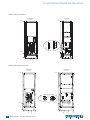
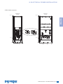
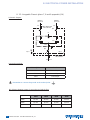
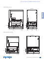
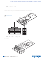
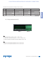
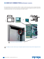
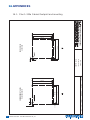
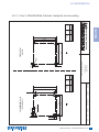
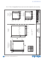
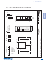
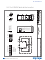
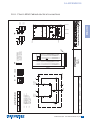
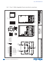
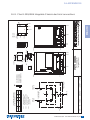
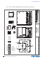
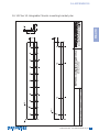
INDEX
9. ELECTRICAL INSTALLATION OF AUXILIARY CONNECTIONS
Rack Slot
Serial link card
Information card report (ADC card)
Relay terminal block (F)
33
34
34
35
10. DISPLAY CONNECTION (INTEGRABLE CHASSIS)
36
11. COMMISSIONING
37
11. 1.
11. 2.
11. 3.
11. 4.
11. 5.
11. 6.
Start conditions
Power-up of STATYS
Priority source selection
Load supply
Transfer to maintenance bypass
Maintenance bypass return
ENGLISH
9. 1.
9. 2.
9. 3.
9. 4.
32
37
37
37
37
38
38
12. COMMUNICATION INTERFACE
39
12. 1. Profibus
12. 2. Gsm modem
39
39
13. ADVANCED DIAGNOSTICS AND PARAMETERS
39
14. APPENDICES
40
14. 1. Plan 1: 200a Cabinet footprint and mounting
14. 2. Plan 2: 300/400/600a Cabinets footprints and mounting
14. 3. Plan 3: Integrable Chassis and rack slots footprints and mounting
14. 4. Plan 4: 200A Cabinet electrical connections
14. 5. Plan 5: 300/400A Cabinets electrical connections
14. 6. Plan 6: 600A Cabinet electrical connections
14. 7. Plan 7: 200A Integrable Chassis electrical connections
14. 8. Plan 8: 300/400A Integrable Chassis electrical connections
14. 9. Plan 9: 600a Integrable Chassis electrical connections
14. 10. Plan 10: Integrable Chassis mounting bracket plan
40
41
42
43
44
45
46
47
48
49
STATYS 200-600A - Ref.:INMSTA200910-GB_03
7