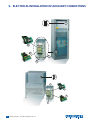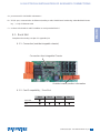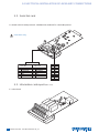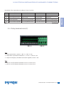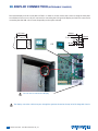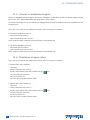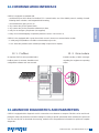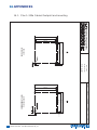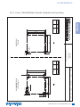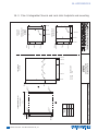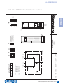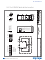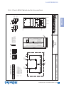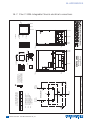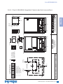
1
STATYS
200-400-600A Cabinet and Integrable Frame
Installation manual
GB
INDEX
1. WARRANTY CERTIFICATE
4
2. PRESENTATION
5
2. 1.
2. 2.
2. 3.
2. 4.
Foreword
The role of Statys
Operating principle
Product range:
3. SAFETY INSTRUCTIONS
3. 1.
3. 2.
3. 3.
3. 4.
3. 5.
Standards and certificates of compliance
Warning plate symbols
Precautions
Electrical risk
Risk of power cut
4. SCHEMATIC DIAGRAMS
5. TRANSPORT, UNPACKING AND HANDLING
5. 1.
5. 2.
5. 3.
5. 4.
Transport
Unpacking
Handling from above
Handling from underneath
6. MECHANICAL INSTALLATION OF CABINETS
6. 1.
6. 2.
6. 3.
Environmental conditions
Mechanical and acoustic characteristics
General Installation Recommendations
5
5
5
5
6
6
6
7
8
8
9
10
10
10
11
13
15
15
15
16
7. MECHANICAL INSTALLATION OF INTEGRABLE UNITS 18
7. 1.
7. 2.
7. 3.
Environmental conditions
Mechanical and acoustic characteristics
General Installation Recommendations
8. ELECTRICAL POWER INSTALLATION
8. 1.
8. 2.
8. 3.
8. 4.
8. 5.
8. 6.
8. 7.
6
Electrical environment
Earthing diagrams
Electrical diagram
Cable sizing
Cable routing
Devices for protecting persons and property
Cabling procedure
STATYS 200-600A - Ref.:INMSTA200910-GB_03
18
18
18
20
20
20
21
27
28
29
30
INDEX
9. ELECTRICAL INSTALLATION OF AUXILIARY CONNECTIONS
Rack Slot
Serial link card
Information card report (ADC card)
Relay terminal block (F)
33
34
34
35
10. DISPLAY CONNECTION (INTEGRABLE CHASSIS)
36
11. COMMISSIONING
37
11. 1.
11. 2.
11. 3.
11. 4.
11. 5.
11. 6.
Start conditions
Power-up of STATYS
Priority source selection
Load supply
Transfer to maintenance bypass
Maintenance bypass return
ENGLISH
9. 1.
9. 2.
9. 3.
9. 4.
32
37
37
37
37
38
38
12. COMMUNICATION INTERFACE
39
12. 1. Profibus
12. 2. Gsm modem
39
39
13. ADVANCED DIAGNOSTICS AND PARAMETERS
39
14. APPENDICES
40
14. 1. Plan 1: 200a Cabinet footprint and mounting
14. 2. Plan 2: 300/400/600a Cabinets footprints and mounting
14. 3. Plan 3: Integrable Chassis and rack slots footprints and mounting
14. 4. Plan 4: 200A Cabinet electrical connections
14. 5. Plan 5: 300/400A Cabinets electrical connections
14. 6. Plan 6: 600A Cabinet electrical connections
14. 7. Plan 7: 200A Integrable Chassis electrical connections
14. 8. Plan 8: 300/400A Integrable Chassis electrical connections
14. 9. Plan 9: 600a Integrable Chassis electrical connections
14. 10. Plan 10: Integrable Chassis mounting bracket plan
40
41
42
43
44
45
46
47
48
49
STATYS 200-600A - Ref.:INMSTA200910-GB_03
7
1. WARRANTY CERTIFICATE
The warranty terms are stipulated in the offer, by default the following clauses apply.
The SOCOMEC UPS warranty is strictly limited to the product(s) and does not extend to equipment which may be
integrated with this(these) product(s), nor the performance of this equipment.
The manufacturer guarantees its material to be free from manufacturing faults and defects in design, material or
workmanship, subject to the limits set forth below.
The manufacturer reserves the right to modify the delivery with a view to fulfilling these guarantees or to replace defective parts. The manufacturer's warranty does not apply in the following cases:
– fault or defect in the design of parts added or supplied by the customer;
– fault due to unforeseen circumstances or force majeure;
– replacement or repair resulting from the normal wear of the modules or machinery;
– damage caused by negligence, lack of proper maintenance or misuse of the products;
– repair, modification, adjustment or replacement of parts performed by unqualified third parties or personnel without the express agreement of SOCOMEC UPS.
The warranty period is twelve months commencing from the date of delivery of the product.
The repair, replacement or modification of the parts during the warranty period does not extend the warranty period.
In order to establish a valid warranty claim, the purchaser must notify the manufacturer in writing immediately after
the discovery of any defects which are attributed to the material and provide any and all supporting evidence of the
defects at the latest within eight days before the date of expiry of the warranty.
Defective parts which have been returned and replaced free of charge shall become the property of SOCOMEC UPS.
The warranty is void if the purchaser has undertaken modifications or repairs on the devices on his or her own initiative and without the express consent of the manufacturer.
The manufacturer's responsibility is strictly limited to the obligations defined in this warranty (repair and replacement)
excluding any other right to claim compensation or indemnity.
Any import tax, duty, fee or charge of any nature whatsoever imposed by European regulations or those of an importing country or of a transit country shall be paid by the purchaser.
4
STATYS 200-600A - Ref.:INMSTA200910-GB_03
2. PRESENTATION
2. 1. Foreword
Thank you for choosing the STATYS Static Transfer System from SOCOMEC UPS.
2. 2. The role of Statys
ENGLISH
STATYS watches permanently both sources of supply and the output to insure the automatic transfer of the use on
the alternate source in case of failure of the priority source and to allow a return of the use on that source when she
will be exploitable.
STATYS is defined by the rating of the current which passes through it by phase (in Amps), irrespective of other electrical characteristics. The power for a given rating is a function of the nominal voltage used.
Two categories of STATYS unit are described in this manual:
- cabinet-mounted STATYS units,
- "integrable chassis" STATYS units, for installation in a custom environment such as distribution switchboards.
2. 3. Operating principle
STATYS is an autonomous electrical device which permits the seamless transfer of the load between an alternate
electrical source S1 and another alternate source S2 (see schematic diagrams § 4).
Under normal operation, STATYS supplies the load from the priority source. The priority source is selected by the
user according to on-site restrictions.
Two transfer modes are possible:
– manual transfer mode, controlled by the operator locally or remotely by means of a BMS or other communicating
system,
– automatic transfer mode, which occurs when an out-of-tolerance voltage is detected on the priority source. The
break-before-make switching principle prevents source overlap.
NOTE: The priority source (source 1 or source 2) is selected using the keyboard and this selection is displayed on-screen.
2. 4. Product range:
STATYS is available in 4 ratings: 200A, 300A, 400A and 600A
Each is available in two installation versions cabinet or integrable chassis version
Different options must be defined when the order is placed (with or without protection fuses, number of poles
switched, mimic panel...)
STATYS 200-600A - Ref.:INMSTA200910-GB_03
5
3. SAFETY INSTRUCTIONS
3. 1. Standards and certificates of compliance
SOCOMEC UPS designs and markets its products in accordance with the following European and international
standards, in addition to meeting the requirements of manufacturers of sensitive electronic and IT equipment.
CEI 62310-1
STS: general requirements and safety regulations
CEI 62310-2
STS: electromagnetic compatibility (EMC) requirements
CEI 62310-3
STS: performance specification method and testing requirements
CEI 60364-4
Electrical installations of buildings
CEI 60950
Information handling material security -
CEI 60529
Degrees of protection provided by the packaging (IP code)
CEI 60439-1
Low voltage equipment
A comprehensive quality process certified to ISO 9001 ensures high-quality production and associated services.
Specifications are subject to change without prior notice.
Do not hesitate to contact your nearest SOCOMEC UPS sales office for further details.
Copyright SOCOMEC UPS.
This equipment conforms to EC directives applicable to this type of product. This conformity is indicated by the CE mark:
3. 2. Warning plate symbols
We remind you of the need to observe the safety recommendations and warnings shown on the labels located inside
and outside of the unit.
Danger ! High voltage (black/yellow)
Ground terminal
Read the user manual before performing any operation
6
STATYS 200-600A - Ref.:INMSTA200910-GB_03
3. SAFETY INSTRUCTIONS
3. 3. Precautions
This document provides essential instructions regarding safety, handling and connections for STATYS cabinetmounted and/or integrable units.
Carefully read this manual before operating STATYS.
ENGLISH
Keep this manual in a safe place for future reference.
CAUTION
For optimal use, it is recommended to maintain the ambient temperature and humidity at the values specified by the
manufacturer.
Do not expose STATYS to rain or any other type of liquid. Do not introduce foreign bodies into the unit.
WARNING
SOCOMEC UPS maintains integral and exclusive ownership of its intellectual and industrial property rights regarding this document. Use of this document is limited to personal use by the recipient for the application specified by
SOCOMEC UPS. Any reproduction, modification or distribution of this document, whether in whole or in part, by any
means whatsoever, is expressly prohibited without the prior written permission of SOCOMEC.
This document is not a specification. SOCOMEC UPS reserves the right to modify the content of this document
without notice.
•This unit must be exclusively installed, commissioned and repaired by specialist technical personnel authorised by
SOCOMEC UPS.
The product which you have chosen taking into consideration its conditions of use, capacities and performance
limits, is designed for commercial and industrial use only.
For use with so-called “critical applications”, the product may be required to comply with legal and regulatory obligations as well as specific local standards, and be adapted based on the recommendations of SOCOMEC UPS. In all
cases where the equipment is to be used for critical applications, you are advised to contact SOCOMEC UPS in advance to confirm that the products are capable of meeting the required levels of safety, performance and reliability.
The term “critical applications” notably includes life support systems, medical applications, commercial transport,
nuclear installations or any other system or application where the failure of the product is likely to cause substantial
damage to persons or property.
STATYS 200-600A - Ref.:INMSTA200910-GB_03
7
3. SAFETY INSTRUCTIONS
3. 4. Electrical risk
WARNING
All operations and maintenance must be performed by authorised personnel who have undertaken suitable training.
Scrupulously follow the operating or maintenance instructions described in this manual.
Take maximum precautions and determine which parts are live:
- by following the load diagrams,
- by checking the presence of power with a voltmeter, for example.
DANGER
The cabinet is permanently powered by sources 1 and 2 if Q41 and Q42 are closed.
In normal operating conditions, there is no danger for personnel handling this equipment.
3. 5. Risk of power cut
WARNING
Scrupulously follow the operating instructions described in this manual to prevent inadvertent power cuts which may
pose a safety hazard to the user.
DANGER
Taking into account the presence of high leakage currents, it is essential to connect the ground cable
before connecting the upstream and load sources.
Hazardous voltage may be present within STATYS after it is switched off.
In fact, the power supply voltage remains present at the input of each static contactor
STATYS MUST be moved by at least two people. They MUST stand on either side of the unit according
to the direction of movement.
8
STATYS 200-600A - Ref.:INMSTA200910-GB_03
4. SCHEMATIC DIAGRAMS
In cabinet
Source 1
Source 2
Q41
Q42
F
Source 1
Source 2
Q41
Q42
ENGLISH
Integrable Chassis
F
CS1
Logique de
commande
Q50-1
CS1
CS2
Q50-2
Logique de
commande
CS2
STATYS
Q50-1
Q30
Q50-2
Q30
STATYS
Load outgoing line
Load outgoing line
KEY:
Q41
= Source 1 input switch*,
Q42
= Source 2 input switch*,
Q30
= Output switch*,
Q50
= Inverter, for source 1 or 2 maintenance bypasses*,
CS1
= Switch 1,
CS2
= Switch 2,
F
= Protection by Fuse (optional),
Dashed-line circuit "- -- -" and components marked "*" = Supplied to customer in Integrable Chassis version.
STATYS 200-600A - Ref.:INMSTA200910-GB_03
9
5. TRANSPORT, UNPACKING AND HANDLING
STATYS is packaged using materials which keep it stable during transport and handling.
During transport and handling, STATYS must be kept in an upright position.
When handling the unit on inclined surfaces (even on surfaces with a minimal incline), use equipment
fitted with suitable braking devices in order to prevent the risk of serious accidents.
5. 1. Transport
Transport the unit as close as possible to the connection area before removing the packaging.
Ensure that the floor can withstand the weight of STATYS
When moving the unit, avoid supporting it by the front panels.
STATYS MUST be moved by at least two people. They MUST stand on either side of the STATYS unit
according to the direction of movement.
If the packaging is damaged on receipt, its content must be immediately collected and isolated. The
shipper or consignee must be contacted.
5. 2. Unpacking
5.2-1
5.2-2
5.2-3
1
2
POSITION STATYS IN ITS INSTALLATION AREA.
All packaging materials must be recycled in accordance with regulations in force in the country of installation.
10
STATYS 200-600A - Ref.:INMSTA200910-GB_03
5. TRANSPORT, UNPACKING AND HANDLING
5. 3. Handling from above
ENGLISH
5.3-1
Never use general-purpose straps!
5. 3.1. Handling 200-300-400-600A cabinets from above
5.3.1-2
5.3.1-1
Remove the plastic caps A.
Fit the lifting rings [M12) supplied on request.
A
STATYS 200-600A - Ref.:INMSTA200910-GB_03
11
5. TRANSPORT, UNPACKING AND HANDLING
5.3.1-3
5.3.1-4
Remove the lifting rings (M12) supplied on request.
The length of the lifting slings must be greater than or equal to 150 cm.
5.3.1-5
5.3.1-6
Refit the plastic caps A.
If the ceiling height is too low,
trusses can be used.
A
5. 3.2. Handling STATYS integrable units from above
The handling of integrable units from above (using slings, spreader beam, straps...) is strictly prohibited.
12
STATYS 200-600A - Ref.:INMSTA200910-GB_03
5. TRANSPORT, UNPACKING AND HANDLING
5. 4. Handling from underneath
5. 4.1. Handling 200A STATYS units from underneath
ENGLISH
5.4.1-1
To facilitate handling, two yellow skis (700mm) are screwed onto the feet, in the widthwise direction
The cabinets can be handled from underneath using a pallet truck or forklift truck, with the forks introduced from the
sides only. Remove the side grids of the cabinet, then position the forks underneath it:
The skis must be detached before the machine is installed in its final position.
STATYS 200-600A - Ref.:INMSTA200910-GB_03
13
5. TRANSPORT, UNPACKING AND HANDLING
5. 4.2. Handling 300-400-600A STATYS units from underneath
To facilitate handling, two yellow skis (700mm) are screwed onto the feet in the depthwise direction.
The cabinets can be handled from underneath using a pallet truck or forklift truck, with the forks introduced from the
front or rear only.
5.4.2-1
5. 4.3. Handling STATYS integrable units from underneath
To facilitate maintenance, two feet are screwed onto the underside of the body, along its width.
The integrable units can be handled from underneath by means of a pallet truck or forklift truck, with the forks introduced from the front or rear only (except for STATYS 200A). Remove the side grids of the cabinet, then position
the forks under the unit.
5.4.3-1
14
STATYS 200-600A - Ref.:INMSTA200910-GB_03
6. MECHANICAL INSTALLATION OF CABINETS
6. 1. Environmental conditions
STATYS has been designed for use in an environment defined as follows:
200A
400A
600A
-25°C -- +70 °C
Humidity (transport and storage)
ENGLISH
Temperature (transport and storage)
300A
0% -- 95%
Operating temperature
0°C -- +40 °C
Operating relative humidity
0% -- 95%
Altitude
maximum 1000 a.s.l without derating
6. 2. Mechanical and acoustic characteristics
200A
Height (mm)
Width (mm)
400A
600A
1930
500
Depth (mm)
Floor space (m3)
300A
700
900
640*
0.24
Degree of protection
0.42
0.54
IP 20
Weight (kg)
195
270
345
Sound pressure dB (A)
60
56
54
Indicates overall dimensions (*including handle)
See plans 1 in 2 in appendix (§14)
STATYS 200-600A - Ref.:INMSTA200910-GB_03
15
6. MECHANICAL INSTALLATION OF CABINETS
6. 3. General Installation Recommendations
6. 3.1. Environment
See the technical data table (§ 6.1) for permissible temperature, humidity and altitude values. If necessary, cooling
and air conditioning systems should be used.
Avoid dusty atmospheres or environments containing dust from conductive or corrosive materials (e.g. dust from
metal or chemical solutions).
Use STATYS only in a closed environment.
Do not expose STATYS to direct sunlight or excessive heat sources.
STATYS provides front access to the breaker components; leave a minimum space of 1.5 metres in front of STATYS to
allow for maintenance work.
The skis must be detached before the machine is installed in its final position.
6. 3.2. Installation on raised technical flooring
In the event of installation on technical flooring, a frame must be used to support the weight of the unit (figure 6.3.2-1).
Cold air is drawn in through the front and hot air exits through the top of the unit.
6.3.2-1
6.3.2-2
DOOR
STATYS
COLD
AIR
HOT
AIR
16
STATYS 200-600A - Ref.:INMSTA200910-GB_03
6. MECHANICAL INSTALLATION OF CABINETS
6. 3.3. Installation above air duct
ENGLISH
6.3.3-1
6. 3.4. Cooling and air conditioning
6.3.4-2 Air conditioning.
6.3.4-1 Cooling.
HOT
AIR
STATYS
COLD
AIR
AIR CONDITIONING
AIR CONDITIONING
200A
Cooling
HOT
AIR
STATYS
STATYS
COLD
AIR
300A
400A
600A
forced cooling (redundant)
Air flow (m3 / h)
553
Max Dissipation (W)
1330
642
1690
627
2530
3730
When fitting the modules in their environment, ensure that there is sufficient space to allow for unrestricted air flow
and heat dispersal (see §6.3).
STATYS 200-600A - Ref.:INMSTA200910-GB_03
17
7. MECHANICAL INSTALLATION OF INTEGRABLE UNITS
7. 1. Environmental conditions
STATYS has been designed for use in an environment defined as follows:
200A
Transport and storage temperature
300A
400A
600A
-20°C -- +70 °C
Transport and storage relative humidity
0% -- 95%
Operating temperature
0°C -- +40 °C
Operating relative humidity
0% -- 95%
Altitude
maximum 1000 a.s.l without derating
7. 2. Mechanical and acoustic characteristics
200A
300A
Height (mm)
Width (mm)
600A
765
400
600
Depth (mm)
Floor space (m3)
400A
800
586
0.18
0.27
Degree of protection
0.36
IP 20
Weight (kg)
70
Sound pressure dB (A)
63
105
50
130
60
59
Indicates overall dimensions
See plan 3 in appendix (§14)
7. 3. General Installation Recommendations
7. 3.1. Environment
See the technical data table (§ 7.1) for permissible temperature, humidity and altitude values. If necessary, cooling
and air conditioning systems should be used.
Avoid dusty atmospheres or environments containing dust from conductive or corrosive materials (e.g. dust from
metal or chemical solutions).
Only use STATYS in an internal environment.
Do not expose STATYS to direct sunlight or excessive heat sources.
The detachable feet must be removed before the machine is installed in its final position.
18
STATYS 200-600A - Ref.:INMSTA200910-GB_03
7. MECHANICAL INSTALLATION OF INTEGRABLE UNITS
7. 3.2. Cabinet-mounted installation of STATYS
The integrable chassis can be installed in one of two ways:
– Placed on crossbeams and fastened from underneath using screws (see plan 3 in appendix §14)
– Fastened on the sides by 4 x M6 threaded inserts on each side (see plan 3 in appendix §14). You can also use the
ENGLISH
brackets supplied on request (see plan 10 in appendix §14).
Do not fasten the integrable chassis using the front and rear panels.
When fitting the modules in their environment, ensure there is sufficient space to allow for unrestricted
air flow and heat dispersal (200 mm under chassis).
Multiple integrable units can be installed in the same cabinet. Nevertheless, air flowing out from the
top panel of an integrable unit must not be used to cool other integrable units.
7. 3.3. Cooling
Air inflow:
If the underside of the integrable chassis is not obstructed, air is drawn through it.
If the underside of the integrable chassis is obstructed, air is drawn through the front panel.
To prevent impaired thermal performance of the STATYS unit mounted in a cabinet with the underside
obstructed or blocked, it must be raised by 200 mm so that the fans draw air from the front panel at
door level.
Air outflow:
Air flows out through the top surface of the integrable chassis
Ensure that there is a minimum distance of 50 mm between the roof grid of STATYS and the roof grid
of the cabinet.
200A
Type of cooling
300A
400A
600A
Forced cooling
Required air flow (m3 / h)
553
Dissipation (W)
1090
642
1430
627
1990
3020
STATYS 200-600A - Ref.:INMSTA200910-GB_03
19
8. ELECTRICAL POWER INSTALLATION
8. 1. Electrical environment
Inputs / Output
200A
Voltage (V)
300A
+/- 10%
Overload
60 minutes: 110% - 2 minutes: 150%
30
Frequency (Hz)
45
45
45
50 or 60
Frequency tolerance
Sizing of neutral
600A
208 - 220 / 380 - 415 / 440
Voltage tolerance
Max short circuit current (kA)
400A
Configurable +/- 10%
315A
630A
1000A
8. 2. Earthing diagrams
The STATYS range is compatible with all earthing systems. Nevertheless you should ensure that you have a suitable
safety device (3-pole breaker or 4-pole breaker) installed.
20
STATYS 200-600A - Ref.:INMSTA200910-GB_03
8. ELECTRICAL POWER INSTALLATION
8. 3. Electrical diagram
8. 3.1. Cabinet (plans 4, 5 and 6 appendix §14)
6285&(
3K1
6285&(
3K1
3(
;
ENGLISH
Schematic diagram:
3(
;
4
4
S
S
)
)
;
;
&6
&6
;
4
, ,,
S
4,
4,,
S
S
;
3K1
3(
)[[[RSWLRQ
Connection terminals:
Description
Load
Description
Load
X10
Source 1 phases input
Q41 / Q42
Input switch
X20
Source 2 phases input
Q30
Output switch
X30
Load phases output
Q50 (I - 0 - II)
Maintenance bypass
Remember to connect the ground at the marked point
Min. distance between centre of connection pad and the floor:
200A
300A
400A
600A
240 mm
340 mm
340 mm
290 mm
X10
X20
X30
STATYS 200-600A - Ref.:INMSTA200910-GB_03
21
8. ELECTRICAL POWER INSTALLATION
STATYS 200A connection:
VUE DE DROITE
VUE DE FACE
RIGHT VIEW
FRONT VIEW
1930 mm
1930 mm
X20-N
X10
X30
X10-N
X30-L1
X10-L1
X30-L2
X10-L2
X30-L3
X10-L3
Q30
Q42
X20-L1
X20-L2
Q41
X20-L3
Q50
240 mm
500 mm
310 mm
180 mm
600 mm
420 mm
X20
300 mm
240 mm
X30-N
STATYS 300-400A connection:
VUE DE DROITE
VUE DE FACE
RIGHT VIEW
FRONT VIEW
1930 mm
1930 mm
Q50
Q42
Q30
X30-N
X30-L1
X30-L2
X30-L3
340 mm
Q41
X10-L1
X20-L1
X10-L3
X20-L3
340 mm
STATYS 200-600A - Ref.:INMSTA200910-GB_03
700 mm
450 mm
240 mm
600 mm
*
X20
420 mm
265 mm
X10
X30
22
X10-N
X20-N
X10-L2
X20-L2
8. ELECTRICAL POWER INSTALLATION
STATYS 600A connection:
VUE DE DROITE
VUE DE FACE
RIGHT VIEW
FRONT VIEW
1930 mm
ENGLISH
1930 mm
X30-N
X30-L1
X30-L2
X30-L3
X10-L2
X20-L2
Q50
Q42
X10-L1
X20-L1
Q30
Q41
X10-L3
X20-L3
290 mm
900 mm
580 mm
320 mm
X20
600 mm
265 mm
120 mm
X10
X30
420 mm
290 mm
X10-N
X20-N
STATYS 200-600A - Ref.:INMSTA200910-GB_03
23
8. ELECTRICAL POWER INSTALLATION
8. 3.2. Integrable Chassis (plans 7, 8 and 9 appendix §14)
Schematic diagram:
SOURCE 1
3Ph+N+PE
X10
Q41
SOURCE 2
3Ph+N+PE
HORS FOURNITURE
NOT SUPPLIED
X20
Q42
4p
4p
PE
X100
X200
CS1
CS2
X300
PE
Q30
I 0I I
4p
Q50-I
Q50-II
4p
4p
HORS FOURNITURE
NOT SUPPLIED
X30
3Ph+N+PE
Connection terminals:
Description
Load
X100
Source 1 input
X200
Source 2 input
X300
Load output
Remember to connect the ground at the marked point
Min. distance between centre of connection pad and the floor:
24
200A
300A
400A
600A
X100
70 mm
35 mm
35 mm
35 mm
X200
70 mm
35 mm
35 mm
35 mm
X300
65 mm
57 mm
57 mm
57 mm
STATYS 200-600A - Ref.:INMSTA200910-GB_03
8. ELECTRICAL POWER INSTALLATION
STATYS 200A connection:
ENGLISH
front view
65 mm
70 mm
L3
N
L1 L2 L3
X200
400 mm
L1 L2
X100
27 mm
48 mm
545 mm
586 mm
N
192 mm
L3
223 mm
L1 L2
X300
N
STATYS 300-400A connection:
front view
57 mm
35 mm
L3
N
L1
L2
X 200
L3
600 mm
L1
L2
X 100
334 mm
50 mm
71 mm
N
L3
586 mm
L1
L2
X300
520 mm
175 mm
N
STATYS 200-600A - Ref.:INMSTA200910-GB_03
25
8. ELECTRICAL POWER INSTALLATION
STATYS 600A connection:
front view
57 mm
35 mm
26
L1
L2
L3
N
STATYS 200-600A - Ref.:INMSTA200910-GB_03
L1
L2
L3
X200
441 mm
113 mm
50 mm
X100
800 mm
N
L3
586 mm
L1
L2
X300
533 mm
175 mm
N
8. ELECTRICAL POWER INSTALLATION
8. 4. Cable sizing
The connection pads are adapted for connection of copper cables. The connection pads cannot receive tinned conductors. These pads are spaced at 30mm intervals, which prevents accidental contact between 1 strand and a pad
ENGLISH
8. 4.1. Ground cable
Failure to observe grounding procedures may lead to the risk of electrical shock, or the risk of fire if a
ground fault occurs.
Screw diameter
Cabinet
Integrable
3 x diameter 10
3 x M8
Remember to connect the ground at the marked point
Ground connections must be in compliance with local regulations and applicable standards
8. 4.2. Neutral (N or PEN)
Cabinet
Rating [A]
200
300
Integrable
400
600
Screw diameter
1 x 11
2 x 13 mm²
3x13
Diameter (mm²)
1 x 185
2 x 240
3 x 240
Tightening torque (Nm)
26
45
200
300
400
1 x M10
1 x 150
2 x 185
600
1 x M12
2 x 240
26
45
The neutral is not always wired and depends on the neutral condition of the installation (see § 8.3)
Ground connections must be in compliance with local regulations and applicable standards
STATYS 200-600A - Ref.:INMSTA200910-GB_03
27
8. ELECTRICAL POWER INSTALLATION
8. 4.3. Phases or PE
Cabinet
Rating [A]
200
300
Integrable
400
600
Screw diameter
1 x 11
2 x 13 mm²
3 x 13
Diameter (mm²)
1 x 150
2 x 150
3 x 185
Tightening torque (Nm)
26
200
300
400
1 x M10
1 x 120
1 x 240
45
600
1 x M12
2 x 185
26
45
8. 5. Cable routing
8.5-1 Correct installation.
Common
mains
8.5-2 Authorised installation.
Common
mains
Control
cables 1
Load
N
N
N
N
Aux mains
Mains
Control
cables 1
Load
N
Load
N
Control
cables 1
N
Mains
≥10 cm
≥10 cm
Aux mains
Load
N
N
≥10 cm
8.5-3 Incorrect installation.
Control
cables 1
N
≥10 cm
≥10 cm
Control cables1: connections between the cabinets and each unit, alarm messages, remote
mimic panel, BMS connection, emergency stop,
connection to breaker components...
N
N
N
N
N
Power cables and control cables must never be installed in the same raceway
Power cables near to sensitive equipment must not be exposed to electromagnetic fields.
28
STATYS 200-600A - Ref.:INMSTA200910-GB_03
8. ELECTRICAL POWER INSTALLATION
8. 6. Devices for protecting persons and property
8. 6.1. Backfeed protection
In order to comply with the standard, STATYS is fitted with a control for backfeed protection devices. In case of
default on one input, STATYS delivers a voltage signal on terminal block XB2 (see § 9.3) to triggers the breaker com-
ENGLISH
ponent by means of a pulse-type shunt trip coil.
In the integrable chassis version, the L1/ L3 voltage must be returned to the level of the fuse holder.
It is a phase to phase voltage
Backfeed cabling is mandatory
The breaker components triggered by the shunt trip coils must be marked with a warning label
8. 6.2. Internal protective device (Cabinet model only)
Depending on the STATYS model ordered, an internal protective device may be present:
200A
300A
400A
600A
Calibre fusible UR (A)
400
630
1000
I²t pré-arc à 1ms (kA²s)
19
54
240
I²t total à 440V (kA²s)
65
182
812
If possible, replace using an identical model of the same brand.
In any case the neutral is not protected (never broken).
The internal protective does not provide external upstream protection.
8. 6.3. External upstream protection
These protective devices need to be selected and configured taking into account the size of the STATYS unit, the
installation and the diameter of cable used.
Neutral rating if the load is non-linear (x 1.7).
The installation's short-circuit current must not exceed that permitted by STATYS (see § 8.1)
8. 6.4. TNC wiring
Available optional, cables allow to connect each neutrals with the ground in the case of a connecting on an installation using the plan of TNC connection.
STATYS 200-600A - Ref.:INMSTA200910-GB_03
29
8. ELECTRICAL POWER INSTALLATION
8. 7. Cabling procedure
8. 7.1. Preliminary checks
Ensure that STATYS is correctly installed in its final position.
Check that the installation is isolated.
Set all switches to position 0.
8. 7.2. Cabinet cabling
Remove the protective devices to gain access to the power connections.
Check that the ground connector is clamped in firm contact with ground.
Check that the other installation devices are securely attached to this ground.
The diameter of the cable must comply with table § 8.5.
Fit a cable linking the ground connector to the PE terminal block.
Wire the source 1 phases on terminal block X10. Pay attention to the direction of rotation of the phases.
Note : Whether or not the neutral is wired on terminal block X10 depends on your neutral condition.
Wire the source 2 phases on terminal block X20. Pay attention to the direction of rotation of the phases.
Note: Whether or not the neutral is wired on terminal block X20 depends on your neutral condition.
Wire the output on terminal block X30. Pay attention to the direction of rotation of the phases.
Note: Whether or not the neutral is wired on terminal block X30 depends on your neutral condition.
Refit the protective panels.
30
STATYS 200-600A - Ref.:INMSTA200910-GB_03
8. ELECTRICAL POWER INSTALLATION
8. 7.3. Integrable chassis cabling
Remove the protective panels to gain access to the power connections.
Check that the ground connector is clamped firmly in contact with ground.
ENGLISH
Check that the other installation devices are securely attached to ground.
The diameter of the cable must comply with table 8.5.
Wire the ground connector to the PE terminal block.
Wire the source 1 phases on terminal block X100. Pay attention to the direction of rotation of the phases.
Note: Whether or not the neutral is wired on terminal block X100 depends on your neutral condition.
Wire the source 2 phases on terminal block X200. Pay attention to the direction of rotation of the phases.
Note: Whether or not the neutral is wired on terminal block X200 depends on your neutral condition.
Wire the output on terminal block X300. Pay attention to the direction of rotation of the phases.
Note: Whether or not the neutral is wired on terminal block X300 depends on your neutral condition.
Refit the protective panels.
STATYS 200-600A - Ref.:INMSTA200910-GB_03
31
9. ELECTRICAL INSTALLATION OF AUXILIARY CONNECTIONS
A
B
D
1
2
3
4
E
C
F
A
B
C
D
1
2
3
4
E
F
32
STATYS 200-600A - Ref.:INMSTA200910-GB_03
9. ELECTRICAL INSTALLATION OF AUXILIARY CONNECTIONS
A = port reserved for SOCOMEC maintenance
B = TCP/IP port, communication via Ethernet (sending e-mails, SNMP-based monitoring, embedded Web browsing, ...) => RJ45 Ethernet cable
ENGLISH
C = 4-slot rack for boards D and E in addition to a relay terminal block F:
9. 1. Rack Slot
Footprint and mounting: see plan 3 in appendix §14
9. 1.1. Connection (outside integrable chassis):
Connection from Integrable Chassis
Outside inverter position information
9. 1.2. Card Compatibility / Com Slot:
Slot 1
Serial link
O
ADC
O
Slot 2
Slot 3
Slot 4
O
O
O
STATYS 200-600A - Ref.:INMSTA200910-GB_03
33
9. ELECTRICAL INSTALLATION OF AUXILIARY CONNECTIONS
9. 2. Serial link card
D = RS485 or RS232 serial port board - PROFIBUS DP, ModBus RTU or DeviceNet protocol
Com Slot 1 only
RT X+
RS485
2 FILS JBUS
1 RTx+
2 RTx3 ALIM TELES.
4 NC
5 NC
6 GNDI
RS232
1 NC
2 Rx
3 Tx
4 NC
5 GNDI
6 NC
7 NC
8 NC
9 NC
RS485 / RS422
4 FILS JBUS
1 RTx+
2 RTx3 ALIM TELES.
4 Rx+
5 Rx6 GNDI
9. 3. Information card report (ADC card)
E = alarm board
OUT
2
OUT
1
IN1
IN1
IN2
IN3
OUT
3
OUT
4
34
STATYS 200-600A - Ref.:INMSTA200910-GB_03
RTX–
9. ELECTRICAL INSTALLATION OF AUXILIARY CONNECTIONS
Description of the output alarm according to chosen Com Slot:
Slot 1
Slot 2
Slot 3
Slot 4
C1
Load on preferred source
Source 1 OK
Electronic alarm
Load not supplied
C2
Load on alternate source
Source 2 OK
Overload alarm
Output OK
C3
Transfer impossible
Sources are synchronised
Imminent stop
Load on manual by pass 1
C4
Auto re-transfer impossible
S1 is the preferred source
Consecutive detection
Load on manual by pass 2
ENGLISH
Relay
9. 4. Relay terminal block (F)
4 3 2 1
8 7 6 5 4 3 2 1
XB 1
XB 2
XB 1:
• 1 output general alarm, contact 1 = NO, 2 = COM, 3 = NC,
• 1 output alarm of preventive maintenance , 4 = NO, 5 = COM, 6 = NC,
• 1 output for Emergency Shutdown Device (Not supplied), contact 7 et 8.
XB 2:
• 1 relay for cut off of upstream protection source 1, contact 1 et 2,
• 1 relay for cut off of upstream protection source 2, contact 3 et 4.
STATYS 200-600A - Ref.:INMSTA200910-GB_03
35
10. DISPLAY CONNECTION (INTEGRABLE CHASSIS)
The remote display must be connected to STATYS. In order to do this, remove the screws securing the front plate.
You will then have access to a RJ-45 connector for connecting the LCD type D20 display and a HE-10 connector for
connecting the ADICOM colour screen, depending on the option selected.
183.5 mm
176.5 mm
96 mm
48 mm
D 22.5 mm
OR
40 mm
36 mm
20 mm
Do not use to connect the display
The display connection cable must pass through the grommet located at the top left of the integrable chassis
36
STATYS 200-600A - Ref.:INMSTA200910-GB_03
11. COMMISSIONING
11. 1. Start conditions
- Source 1 and Source 2 voltages are present.
In the case of a standard cabinet installation:
- switches Q41, Q42, Q30 are open,
ENGLISH
- inverter Q50 is set to position "0".
11. 2. Power-up of STATYS
- Close switches Q41 and Q42.
At this stage, the mimic panel lights up and the control electronics are powered ON. According to the autorestart
configuration (see operating manual) conduction can then be activated on the output.
11. 3. Priority source selection
Note: According to the factory default setting, the priority source is source 1.
Under normal operation, the load is supplied by the priority source.
REMINDER: automatic transfer switches the supply from the priority source to the alternate source. It is therefore
important that the user defines the priority source.
The priority source is selected in "programming" mode (see operating manual).
11. 4. Load supply
If conduction is not activated, the user may force the conduction (see see operating manual Monitoring mode).
When STATYS is in conduction state, close switch Q30. The
icon lights up.
STATYS 200-600A - Ref.:INMSTA200910-GB_03
37
11. COMMISSIONING
11. 5. Transfer to maintenance bypass
STATYS is equipped with two bypasses (except the "integrable" model) which enable it to directly supply the load
from source 1 or 2 without interrupting your application's power supply.
This function is entirely secure, the switches are equipped with mechanical and electronic locks to minimise the risk
of human error.
Since each source has its own maintenance bypass, two cases may be considered:
a. The load is supplied by source 1:
– set inverter Q50 to position I,
– open switches Q30, Q41 and Q42.
At this stage, the static contactors and the electronics are powered OFF.
b. The load is supplied by source 2:
– set inverter Q50 to position I,
– open switches Q30, Q41 and Q42.
At this stage, the static contactors and the electronics are powered OFF.
11. 6. Maintenance bypass return
Since each source has its own maintenance bypass, two cases may be considered:
a. Inverter Q50 is set to position I:
– close Q41,
– switch conduction onto source 1
– visually check that the green LED of static switch 1
is lit,
– once the LED is lit, close Q30,
– set Q50 to position "0".
– also close Q42 to enable a further switch.
b. Inverter Q50 is set to position II:
– close Q42,
– switch conduction onto source 2,
– visually check that the green LED of static switch 2
– once the LED is lit, close Q30,
– set Q50 to position "0".
– also close Q41 to enable a further switch.
38
STATYS 200-600A - Ref.:INMSTA200910-GB_03
is lit,
12. COMMUNICATION INTERFACE
STATYS is equipped as standard with:
– one Ethernet port which allows for ModBus TCP communication, use of the SNMP protocol, sending of emails
following alarm activation, and integrated Web browsing,
– one terminal block giving access to:
• 1 dry contact relay for the general alarm,
ENGLISH
• 1 dry contact relay for the preventive maintenance alarm,
• 1 relay for an emergency stop button (not supplied),
• 2 relays for accidental tripping of upstream protection (source 1 and source 2).
STATYS is also equipped with 4 spare slots which can each house one communication module:
– 1 serial port (JBus/ModBus or Profibus or DeviceNet) only on slot ,
– 1 to 4 alarm relay modules (each module providing 3 inputs and 4 outputs).
12. 1. Profibus
12. 2. Gsm modem
On request, STATYS can be provided with a
Enables sending of SMS messages
Profibus protocol converter, installation and
regarding the equipment’s operating
configuration software and user manuals.
status.
RS232
13. ADVANCED DIAGNOSTICS AND PARAMETERS
STATYS is equipped with a diagnostic card for connection to a maintenance computer. This link can be used for adjusting the advanced parameters and other settings according to specific operational needs. Maintenance personnel
can also use this link to download the event log, statistics and comprehensive information for rapid and complete
diagnostics
STATYS 200-600A - Ref.:INMSTA200910-GB_03
39
STATYS 200-600A - Ref.:INMSTA200910-GB_03
DATE
DATE
30 mm
REV.
REV.
30 mm
ETABLI
ISSUED BY
60 mm
MODIFICATIONS
500 mm
440 mm
MODIFICATIONS
13
SPACE REQUIREMENT
570 mm
VERIFIE
CHECKED BY
606 mm
APPROUVE
640 mm
APPROUVED BY
40 mm
45 mm
40
CABINET FIXING
FIXATION ARMOIRE
STATYS 200A
80 mm
ENCOMBREMENT AU SOL
15
500 mm
420 mm
640 mm
520 mm
595 mm
Innovative Power Solutions
ABOVE VIEW
VUE DE DESSUS
14. APPENDICES
14. 1. Plan 1: 200a Cabinet footprint and mounting
REV.
REV.
50 mm
DATE
DATE
80 mm
115 mm
47 mm
ISSUED BY
ETABLI
14
75 mm
13
MODIFICATIONS
MODIFICATIONS
X mm
Y mm
80 mm
CHECKED BY
VERIFIE
450 mm
SPACE REQUIREMENT
APPROUVED BY
APPROUVE
700
900
mm
300/400A
600A
595 mm
X
640 mm
ARMOIRE
BOARD
600
800
mm
Y
40 mm
45 mm
CABINET FIXING
FIXATION ARMOIRE
STATYS 300/400/600A
80 mm
ENCOMBREMENT AU SOL
15
X mm
Y mm
595 mm
300/400A
600A
ARMOIRE
BOARD
640 mm
520 mm
700
900
X
mm
STATYS 200-600A - Ref.:INMSTA200910-GB_03
ENGLISH
Innovative Power Solutions
ABOVE VIEW
VUE DE DESSUS
620
820
Y
mm
14. APPENDICES
14. 2. Plan 2: 300/400/600a Cabinets footprints and mounting
41
DATE
DATE
551 mm
577 mm
26 mm
REV.
REV.
20 mm
mm
ETABLI
MODIFICATIONS
MODIFICATIONS
400
600
800
200A
300-400A
600A
ISSUED BY
X
VERIFIE
CHECKED BY
APPROUVE
275 mm
765 mm
APPROUVED BY
O 8,5
O 8,5
ARMOIRE
BOARD
O 8,5
O 8,5
X mm
38 mm
M6 : 15mm
M6 : 15mm
M6
M6
415 mm
Chassis Intégrable
Integrable Chassis
STATYS
MAXIMUM LENGTH
TRAD
M6
LATERAL VIEW
M6
247 mm
M6
M6
MONTAGE A DROITE
RIGHT MOUNTED
Innovative Power Solutions
27.5 mm
115 mm
227 mm
202.5 mm
27.5 mm
115 mm
227 mm
202.5 mm
MONTAGE A GAUCHE
LEFT MOUNTED
STANDARD
STANDARD
COM SLOTS
COM SLOTS
104.5 mm
SPACE REQUIREMENT
162 mm
VUE LATERALE
180 mm
STATYS 200-600A - Ref.:INMSTA200910-GB_03
104.5 mm
42
180 mm
ENCOMBREMENT AU SOL
14. APPENDICES
14. 3. Plan 3: Integrable Chassis and rack slots footprints and mounting
247 mm
577 mm
539 mm
REV.
REV.
DATE
DATE
X30 :
X20 :
X10 :
Q50-I
ISSUED BY
ETABLI
4p
I 0II
MODIFICATIONS
MODIFICATIONS
VERIFIE
PE
CHECKED BY
3Ph+N
X30
4p
X200
CS2
X100
CS1
Q30
4p
F421*
Q42
X20
Q50-II
4p
Fxxx*: option
PE
APPROUVED BY
APPROUVE
SOURCE 2
3Ph+N
F411*
X300
PE
X30
200A
4p
Q41
X10
SOURCE 1
3Ph+N
ARRIVEE RESEAU SOURCE 1
MAINS INPUT SOURCE 1
ARRIVEE RESEAU SOURCE 2
MAINS INPUT SOURCE 2
SORTIE UTILISATION
LOAD OUTPUT
X20
200A
ADICOM
ADICOM
B
1930 mm
STATYS 200A
Armoires
Cabinet
STATYS
500 mm
STS
A
m
0m
64
CONNEXION ETHERNET
ETHERNET CONNECTION
ACCES MAINTENANCE
MAINTENANCE ACCESS
Q30
C
Q50
Q41
Q42
X10-L3
X30-L3
B
X10-L2
X30-L2
ENGLISH
Innovative Power Solutions
240 mm
1930 mm
X10-L1
X10-N
C
X30-L1
X30-N
180 mm
MODEL
Volts
X10
3STA 200A 380-415V 200A
A
310 mm
D20
D20
500 mm
COURANT MAXIMUM ADMISSIBLE
MAXIMUM CURRENT WITH STAND
X20-L3
X20-L2
X20-L1
X20-N
14. APPENDICES
14. 4. Plan 4: 200A Cabinet electrical connections
STATYS 200-600A - Ref.:INMSTA200910-GB_03
43
STATYS 200-600A - Ref.:INMSTA200910-GB_03
REV.
REV.
DATE
X20
300A
400A
ISSUED BY
ETABLI
4p
I 0II
MODIFICATIONS
MODIFICATIONS
VERIFIE
PE
CHECKED BY
3Ph+N
X30
4p
X200
CS2
X100
CS1
Q30
4p
F421*
Q42
X20
SOURCE 2
3Ph+N
4p
X300
PE
X30
300A
400A
F411*
Q41
X10
SOURCE 1
3Ph+N
ARRIVEE RESEAU SOURCE 1
MAINS INPUT SOURCE 1
ARRIVEE RESEAU SOURCE 2
MAINS INPUT SOURCE 2
SORTIE UTILISATION
LOAD OUTPUT
Volts
X10
380-415V 300A
380-415V 400A
Q50-I
DATE
X30 :
X20 :
X10 :
MODEL
3STA 300A
3STA 400A
A
APPROUVED BY
APPROUVE
Fxxx*: option
4p
PE
Q50-II
D20
D20
1930 mm
STS
B
A
700 mm
STATYS
Armoires
Cabinet
64
m
0m
CONNEXION ETHERNET
ETHERNET CONNECTION
ACCES MAINTENANCE
MAINTENANCE ACCESS
STATYS 300/400A
ADICOM
ADICOM
Q30
Q50
C
Q41
Q42
B
X10-N
X20-N
X10-L2
X20-L2
C
700 mm
X10-L1
X20-L1
X10-L3
X20-L3
Innovative Power Solutions
340 mm
1930 mm
X30-N
X30-L1
X30-L2
X30-L3
240 mm
44
450 mm
COURANT MAXIMUM ADMISSIBLE
MAXIMUM CURRENT WITH STAND
14. APPENDICES
14. 5. Plan 5: 300/400A Cabinets electrical connections
REV.
REV.
DATE
ISSUED BY
ETABLI
4p
I 0 II
MODIFICATIONS
MODIFICATIONS
3Ph+N
X30
4p
CHECKED BY
VERIFIE
PE
X200
CS2
X100
CS1
Q30
4p
F421*
Q42
X20
SOURCE 2
3Ph+N
F411*
X300
PE
X30
600A
4p
Q41
X10
SOURCE 1
3Ph+N
ARRIVEE RESEAU SOURCE 1
MAINS INPUT SOURCE 1
ARRIVEE RESEAU SOURCE 2
MAINS INPUT SOURCE 2
SORTIE UTILISATION
LOAD OUTPUT
Q50-I
DATE
X30 :
X20 :
X10 :
X20
600A
Fxxx*: option
4p
APPROUVED BY
APPROUVE
Q50-II
PE
ADICOM
ADICOM
1930 mm
STATYS
A
500 mm
900 mm
STS
Armoires
Cabinet
m
m
40
6
CONNEXION ETHERNET
ETHERNET CONNECTION
ACCES MAINTENANCE
MAITENANCE ACCESS
STATYS 600A
400 mm
B
290 mm
1930 mm
X30-L3
X30-L1
Q30
X10-L2
X20-L2
Q50
X10-N
X20-N
C
Q41
Q42
B
ENGLISH
Innovative Power Solutions
X30-L2
X30-N
C
320 mm
Volts
X10
380-415V 600A
A
580 mm
MODEL
3STA 600A
D20
D20
X10-L3
X20-L2
X10-L1
X20-L1
900 mm
COURANT MAXIMUM ADMISSIBLE
MAXIMUM CURRENT WITH STAND
14. APPENDICES
14. 6. Plan 6: 600A Cabinet electrical connections
STATYS 200-600A - Ref.:INMSTA200910-GB_03
45
DATE
DATE
Q50-I
REV.
REV.
4p
I 0II
X300 :
X200 :
X100 :
X200
200A
X300
ETABLI
ISSUED BY
4p
PE
MODIFICATIONS
MODIFICATIONS
3Ph+N+PE
X30
Q30
Q50-II
4p
VERIFIE
CHECKED BY
APPROUVE
APPROUVED BY
65 mm
765 mm
CONNEXION ETHERNET
ETHERNET CONNECTION
ACCES MAINTENANCE
ACCESS MAINTENANCE
HORS FOURNITURE
NOT SUPPLIED
CS2
4p
CS1
PE
X200
4p
Q42
X100
Q41
X20
X10
HORS FOURNITURE
NOT SUPPLIED
SOURCE 2
3Ph+N+PE
X300
200A
SOURCE 1
3Ph+N+PE
ARRIVEE RESEAU SOURCE 1
MAINS INPUT SOURCE 1
ARRIVEE RESEAU SOURCE 2
MAINS INPUT SOURCE 2
SORTIE UTILISATION
LOAD OUTPUT
MODEL
Volts
X100
3STA 200A 380-415V 200A
D20
N
L1 L2
X300
L3
40 mm
96 mm
48 mm
D 22.5 mm
Chassis Intégrable
Integrable Chassis
20 mm
183.5 mm
STATYS 200A
192 mm
36 mm
176.5 mm
545 mm
586 mm
ADICOM
N
L1 L2
X100
L3
N
27.5 mm
115 mm
227 mm
202.5 mm
A
L1 L2 L3
X200
COM SLOTS
180 mm
104.5 mm
Innovative Power Solutions
70 mm
765 mm
132 mm
27 mm
48 mm
A
223 mm
STATYS 200-600A - Ref.:INMSTA200910-GB_03
400 mm
46
M6
247 mm
COURANT MAXIMUM ADMISSIBLE
MAXIMUM CURRENT WITH STAND
14. APPENDICES
14. 7. Plan 7: 200A Integrable Chassis electrical connections
DATE
DATE
Q50-I
REV.
REV.
4p
I 0II
X300 :
X200 :
X100 :
X200
300A
400A
X300
ETABLI
ISSUED BY
4p
PE
MODIFICATIONS
MODIFICATIONS
3Ph+N+PE
X30
Q30
Q50-II
4p
VERIFIE
CHECKED BY
APPROUVE
APPROUVED BY
57 mm
765 mm
CONNEXION ETHERNET
ETHERNET CONNECTION
ACCES MAINTENANCE
ACCESS MAINTENANCE
HORS FOURNITURE
NOT SUPPLIED
CS2
4p
CS1
PE
X200
4p
Q42
X100
Q41
X20
X10
HORS FOURNITURE
NOT SUPPLIED
SOURCE 2
3Ph+N+PE
X300
300A
400A
SOURCE 1
3Ph+N+PE
ARRIVEE RESEAU SOURCE 1
MAINS INPUT SOURCE 1
ARRIVEE RESEAU SOURCE 2
MAINS INPUT SOURCE 2
SORTIE UTILISATION
LOAD OUTPUT
Volts
X100
380-415V 300A
380-415V 400A
N
L3
40 mm
L1
L2
X300
D20
96 mm
48 mm
D 22.5 mm
20 mm
Chassis Intégrable
Integrable Chassis
STATYS 300/400A
175 mm
MODEL
3STA 300A
3STA 400A
520 mm
35 mm
765 mm
36 mm
176.5 mm
586 mm
183.5 mm
N
132 mm
L1
L2
X 100
L3
27.5 mm
115 mm
227 mm
202.5 mm
N
COM SLOTS
COM SLOTS
L1
L2
X 200
104.5 mm
A
L3
180 mm
STATYS 200-600A - Ref.:INMSTA200910-GB_03
ENGLISH
Innovative Power Solutions
50 mm
71 mm
ADICOM
334 mm
A
M6
247 mm
600 mm
COURANT MAXIMUM ADMISSIBLE
MAXIMUM CURRENT WITH STAND
14. APPENDICES
14. 8. Plan 8: 300/400A Integrable Chassis electrical connections
47
DATE
DATE
Q50-I
4p
I 0II
X300 :
X200 :
X100 :
380-415V 600A
600A
X200
REV.
X300
ETABLI
ISSUED BY
4p
PE
MODIFICATIONS
MODIFICATIONS
3Ph+N+PE
X30
Q30
Q50-II
4p
VERIFIE
CHECKED BY
APPROUVE
APPROUVED BY
57 mm
765 mm
CONNEXION ETHERNET
ETHERNET CONNECTION
ACCES MAINTENANCE
ACCESS MAINTENANCE
HORS FOURNITURE
NOT SUPPLIED
CS2
4p
CS1
PE
X200
4p
Q42
X100
Q41
X20
X10
HORS FOURNITURE
NOT SUPPLIED
SOURCE 2
3Ph+N+PE
600A
X300
SOURCE 1
3Ph+N+PE
ARRIVEE RESEAU SOURCE 1
MAINS INPUT SOURCE 1
ARRIVEE RESEAU SOURCE 2
MAINS INPUT SOURCE 2
SORTIE UTILISATION
LOAD OUTPUT
REV.
3STA 600A
X100
N
L3
40 mm
96 mm
48 mm
D 22.5 mm
Chassis Intégrable
Integrable Chassis
STATYS 600A
L1
L2
X300
D20
533 mm
Volts
36 mm
176.5 mm
35 mm
765 mm
20 mm
183.5 mm
586 mm
MODEL
175 mm
ADICOM
N
X100
L2
L3
27.5 mm
115 mm
227 mm
202.5 mm
COM SLOTS
N
L1
L2
104.5 mm
X200
L3
A
180 mm
Innovative Power Solutions
L1
132 mm
113 mm
STATYS 200-600A - Ref.:INMSTA200910-GB_03
441 mm
A
M6
247 mm
48
800 mm
COURANT MAXIMUM ADMISSIBLE
MAXIMUM CURRENT WITH STAND
14. APPENDICES
14. 9. Plan 9: 600a Integrable Chassis electrical connections
50 mm
REV.
REV.
DATE
DATE
ISSUED BY
ETABLI
MODIFICATIONS
MODIFICATIONS
CHECKED BY
VERIFIE
APPROUVED BY
APPROUVE
Plan équerre de fixation
Mounting bracket plan
STATYS Châssis Intégrable / Integrable Chassis
ENGLISH
Innovative Power Solutions
14. APPENDICES
14. 10. Plan 10: Integrable Chassis mounting bracket plan
STATYS 200-600A - Ref.:INMSTA200910-GB_03
49
Socomec UPS
worldwide
IN ASIA
IN EUROPE
BELGIUM
PORTUGAL
CHINA
Schaatsstraat, 30 rue du Patinage
B - 1190 Bruxelles
Tel. +32 (0)2 340 02 34
Fax +32 (0)2 346 16 69
[email protected]
Rua Moinho do Cuco
Bloco A
Lj. Dta. - Paz
2640-566 MAFRA
Tel. +351 261 812 599
Fax +351 261 812 570
[email protected]
No.1 Yuanda Road Haidian District, Beijing, 100097
Golden Resource Times Shopping Mall
No. 1001 section B the 2nd issue of business building
Tel. +86 10 8889 2202
Fax +86 10 8889 2150
[email protected]
RUSSIA
Kutuzovsky pr. 13, 44-45
121248 - Moscow
Tel. +7 495 775 19 85
Fax +7 495 775 19 85
[email protected]
B1, IInd Floor, Thiru-Vi-Ka-Industrial Estate
Guindy
Chennai – 600 032
Tel. +91 44 3921 5400
Fax +91 44 3921 5450 — 51
[email protected]
SLOVENIA
MALAYSIA
Savlje 89
SI - 1000 Ljubljana
Tel. +386 1 5807 860
Fax +386 1 5611 173
[email protected]
31 Jalan SS 25/41- Mayang Industrial Park
47301 Petaling Jaya.- Selangor, Malaysia
Tel. +603 7804 1153
Fax +603 7803 8901
[email protected]
SPAIN
SINGAPORE
C/Nord, 22 Pol. Ind. Buvisa
E - 08329 Teià (Barcelona)
Tel. +34 935 407 575
Fax +34 935 407 576
[email protected]
31 Ubi Road 1, Aztech Building
# 01-00 (Annex) - SG - Singapore 408694
Tel. +65 6745 7555
Fax +65 6458 7377
[email protected]
UNITED KINGDOM
THAILAND
Units 7-9 Lakeside Business Park
Broadway Lane - South Cerney
Cirencester - GL7 5XL
Tel. +44 (0)1285 863300
Fax +44 (0)1285 862304
[email protected]
No.9 Soi Vibhavadirangsit 42
Vibhavadirangsit Rd, Ladyao
Chatujak Bangkok 10900
Tel. +66 2 941-1644-7
Fax. +66 2 941-1650
[email protected]
FRANCE
95, rue Pierre Grange
F - 94132 Fontenay-sous-Bois Cedex
Tel. +33 (0)1 45 14 63 90
Fax +33 (0)1 48 77 31 12
[email protected]
GERMANY
Heppenheimerstraße 57
D - 68309 Mannheim
Tel. +49 (0) 621 71 68 40
Fax +49 (0) 621 71 68 44 4
[email protected]
ITALY
Via Leone Tolstoi, 73 - Zivido
20098 San Giuliano Milanese (MI)
Tel. +39 02 98 242 942
Fax +39 02 98 240 723
[email protected]
NETHERLANDS
Bergveste 2F
NL - 3992DE Houten
Tel. +31 (0)30 63 71 504
Fax +31 (0)30 63 72 166
[email protected]
POLAND
Nowowiejska St 21/25
00-665 Warszawa
Tel. +48 (0)22 2345 223
Fax +48 (0)22 2345 223
[email protected]
HEAD OFFICE
SOCOMEC GROUP
S.A. SOCOMEC capital 11 102 300 € - R.C.S. Strasbourg B 548 500 149
B.P. 60010 - 1, rue de Westhouse - F-67235 Benfeld Cedex
SOCOMEC UPS Strasbourg
11, route de Strasbourg - B.P. 10050 - F-67235 Huttenheim Cedex- FRANCE
Tel. +33 (0)3 88 57 45 45 - Fax +33 (0)3 88 74 07 90
[email protected]
SOCOMEC UPS Isola Vicentina
Via Sila, 1/3 - I - 36033 Isola Vicentina (VI) - ITALY
Tel. +39 0444 598611 - Fax +39 0444 598622
[email protected]
www.socomec.com
Non contractual document. © 2008, Socomec SA. All rights reserved.
Valid for France
Valid for Italy
INDIA
SALES, MARKETING AND
SERVICE MANAGEMENT
SOCOMEC UPS Paris
95, rue Pierre Grange
F-94132 Fontenay-sous-Bois Cedex - FRANCE
Tel. +33 (0)1 45 14 63 90 - Fax +33 (0)1 48 77 31 12
[email protected]