1
C2-2855 Universal Scaler PLUS
C2-2755 Video Scaler PLUS
C2-2655 Scan Converter PLUS
User Manual
V1.12
PDF-UG-C2-2X55
Contents
1
DISCLAIMER .......................................................................................................................... 5
Regulatory Agency Acceptance ......................................................................................................................... 5
European ‘CE’ Mark Statement ......................................................................................................................... 5
FCC Statement .................................................................................................................................................. 5
Manual Copyright Notice ................................................................................................................................... 6
2
SAFETY INSTRUCTIONS ...................................................................................................... 7
3
UNPACKING AND INSTALLATION ..................................................................................... 12
3.1
3.2
3.3
4
4.1
4.1.1
4.1.2
4.2
4.3
4.4
4.5
4.6
4.7
4.8
4.8.1
5
5.1
5.2
5.3
5.4
6
6.1
6.2
6.3
6.4
6.5
6.6
6.7
7
7.1.1
7.1.2
7.1.3
7.1.4
7.1.5
8
8.1
8.2
8.2.1
8.2.2
8.2.3
8.3
8.4
8.5
Shipping Carton................................................................................................................................ 12
Important Safety Instructions ........................................................................................................... 12
Initial Operation Check Using Factory Default Settings ................................................................... 12
QUICK START...................................................................................................................... 13
Overview .......................................................................................................................................... 13
Input/Output Connectivity ................................................................................................................. 13
Output Resolution Support ............................................................................................................... 13
Box Contents .................................................................................................................................... 14
C2-2x55 Connections ....................................................................................................................... 14
Menu Overview ................................................................................................................................ 15
Setting an Output Resolution ........................................................................................................... 15
Switching .......................................................................................................................................... 15
C2-2x55 Architecture ........................................................................................................................ 15
Inputs/Outputs .................................................................................................................................. 16
Universal DVI ................................................................................................................................... 16
PANEL INTERFACE............................................................................................................. 18
Panel Overview ................................................................................................................................ 18
Using the C2-2x55............................................................................................................................ 18
OLED Panel Overview ..................................................................................................................... 19
Primary/Background Indicators ........................................................................................................ 19
MENU OVERVIEW ............................................................................................................... 20
Layering Control ............................................................................................................................... 20
Swapping Layers .............................................................................................................................. 21
Genlock & Framelock & Hiding ........................................................................................................ 21
Scaling Overview.............................................................................................................................. 22
Aspect Ratio Conversion .................................................................................................................. 22
Importing Logos ................................................................................................................................ 22
Importing Items................................................................................................................................. 23
BUTTON NAVIGATION ........................................................................................................ 24
Powering Up ..................................................................................................................................... 24
Button Colors .................................................................................................................................... 24
Menu Navigation .............................................................................................................................. 24
Source Selection & Loading Presets ................................................................................................ 24
Other Useful Selections.................................................................................................................... 25
SHORTCUT & LIVE MENUS ................................................................................................ 27
Overview .......................................................................................................................................... 27
Shortcuts & Live Menu Map ............................................................................................................. 28
Shortcuts .......................................................................................................................................... 28
Live Menu ......................................................................................................................................... 29
Primary ............................................................................................................................................. 29
Background ...................................................................................................................................... 29
Audio ................................................................................................................................................ 29
Layer Order ...................................................................................................................................... 30
2|Page
8.6
8.7
8.8
8.9
8.10
9
Keying .............................................................................................................................................. 30
Freeze .............................................................................................................................................. 31
Preset ............................................................................................................................................... 31
Logo.................................................................................................................................................. 31
Transition .......................................................................................................................................... 31
POPULAR TASKS................................................................................................................ 32
9.1
9.1.1
9.1.2
9.2
9.3
9.4
9.4.1
9.4.2
9.5
9.6
9.7
9.8
9.9
10
Setting up Sources and Outputs ...................................................................................................... 32
Source Set up ................................................................................................................................... 32
Output Set Up ................................................................................................................................... 32
Switching Sources ............................................................................................................................ 32
Customizing Transitions ................................................................................................................... 32
Creating a picture in picture effect ................................................................................................... 33
Resizing the Primary Layer .............................................................................................................. 33
Adding a Background ....................................................................................................................... 33
Adding a Color Field as a Background............................................................................................. 33
Adding a Still Image as a Background ............................................................................................. 34
Adding a logo to a presentation ....................................................................................................... 35
Creating a lower third ....................................................................................................................... 35
Using audio from alternative sources ............................................................................................... 36
SETUP MENU....................................................................................................................... 37
10.1
10.2
10.2.1
10.2.2
10.2.3
10.2.4
10.2.5
10.2.6
10.2.7
10.2.8
10.3
10.3.1
10.3.2
10.3.3
10.3.4
10.3.5
10.3.6
10.3.7
10.3.8
10.3.9
10.3.10
10.3.11
10.3.12
10.3.13
10.3.14
10.3.15
10.3.16
10.3.17
10.3.18
10.4
10.4.1
10.4.2
10.4.3
10.5
10.6
10.7
10.8
10.9
Initial Set Up ..................................................................................................................................... 37
Connections ..................................................................................................................................... 37
HDMI ................................................................................................................................................ 38
Universal DVI ................................................................................................................................... 39
3G/HD/SD-SDI ................................................................................................................................. 39
PC/HD .............................................................................................................................................. 39
YC/CV .............................................................................................................................................. 39
Audio Connections ........................................................................................................................... 40
Phoenix Audio .................................................................................................................................. 40
3.5mm Audio Input ........................................................................................................................... 40
Setup Menu ...................................................................................................................................... 41
Setup Menu Map .............................................................................................................................. 41
System ............................................................................................................................................. 41
Sources ............................................................................................................................................ 42
Audio Source .................................................................................................................................... 42
Input Type ........................................................................................................................................ 42
RGB Settings .................................................................................................................................... 43
YUV Settings .................................................................................................................................... 43
Aspect Ratio ..................................................................................................................................... 43
Align.................................................................................................................................................. 43
On Source Loss ................................................................................................................................ 43
De-Interlace ...................................................................................................................................... 43
Diagonal Interpolate ......................................................................................................................... 44
Noise Reduction ............................................................................................................................... 44
Field Swap ........................................................................................................................................ 44
Field Offset ....................................................................................................................................... 44
Procamp ........................................................................................................................................... 44
EDID ................................................................................................................................................. 44
HDCP ............................................................................................................................................... 45
Outputs ............................................................................................................................................. 46
Connectors ....................................................................................................................................... 46
Video ................................................................................................................................................ 46
Audio ................................................................................................................................................ 47
Preset ............................................................................................................................................... 47
Layers ............................................................................................................................................... 47
Back Color ........................................................................................................................................ 47
Genlocking your unit......................................................................................................................... 48
Layer Order ...................................................................................................................................... 48
3|Page
10.10
10.11
10.12
Keying .............................................................................................................................................. 49
Presets ............................................................................................................................................. 49
Transitions ........................................................................................................................................ 49
11
TROUBLESHOOTING AND TECHNICAL SUPPORT .......................................................... 50
12
FREQUENTLY ASKED QUESTIONS ................................................................................... 51
12.1
12.2
12.3
12.4
12.5
12.6
12.7
12.8
12.9
12.10
12.11
13
13.1
13.2
14
14.1
14.2
There is no picture on the Output. .................................................................................................... 51
There is excessive flicker on the Output. ......................................................................................... 51
The Output image is distorted. ......................................................................................................... 51
Some colors appear to be incorrect on the CV/YC output ............................................................... 51
How can I reduce color smearing on CV connections? ................................................................... 51
I can no longer adjust the Output image resolution. ........................................................................ 51
The picture on the video display is black and white. ........................................................................ 51
The picture on the video display is green......................................................................................... 51
The RGB input is selected but the image is rolling or pink. ............................................................. 52
The video signal from my DVD player does not appear to work. ..................................................... 52
Image is flashing, snow is present, or source image does not appear. ........................................... 52
RETURN PROCEDURE ....................................................................................................... 53
Trouble Shooting .............................................................................................................................. 53
To return a unit for repair .................................................................................................................. 53
WARRANTY POLICY ........................................................................................................... 54
Limited Warranty .............................................................................................................................. 54
Limitations ........................................................................................................................................ 54
4|Page
1 Disclaimer
This product is intended for professional and/or home use. This product is not intended for use in a medical
environment and does not have the required certifications for such use. Similarly, use aboard any aircraft or
spacecraft while in flight or as an adjunct to any surface, airborne or marine navigation system or any
offshore marine activity, including control of any watercraft, or any use similar to those specifically herein
mentioned is prohibited. Use in the aforementioned circumstances would require additional testing and
certification.
You have not become the owner of any software - you have merely purchased the right to use the software.
You may make one copy of the software for your own use. Other copies will be deemed a breach of
copyright.
No warranty is made either expressed or implied including but not limited to any implied warranties of
merchantability or fitness for a particular purpose. In no event shall the supplier or manufacturer of this
product be liable for errors found within, or be liable for any direct, indirect or consequential damages or loss
in connection with the purchase or use of this hardware software or manual. The sole and exclusive liability
to the supplier and manufacturer regardless of the form of action shall not exceed the replacement cost of
the materials described herein.
By using this equipment you have indicated that you have agreed to the terms listed above. If you do not
wish to agree or the above terms are contrary to your conditions of purchase you may return the equipment,
unused, to your supplier. All trademarks and copyrights are acknowledged. E&OE.
Regulatory Agency Acceptance
European ‘CE’ Mark Statement
Emissions: BS EN 55103-1:2009+A1:2012 (Generic Emission Standard for all environments: E1-E5)
Immunity: BS EN 55103-2:2009 (Generic Immunity Standard for all environments: E1-E5)
FCC Statement
Class B Device: This equipment has been tested and found to comply with the limits for a Class B digital
device pursuant to Part 15 of the FCC Rules. These limits are designed to provide a reasonable protection
against harmful interference when the equipment is operated in all environments. This equipment generates,
uses and can radiate radio frequency energy and, if not installed and used in accordance with the Instruction
Manual, may cause harmful interference to radio communications.
This Class B Digital Apparatus meets all requirements of the Canadian Interference-Causing Equipment
Regulations.
Cet Appareil Numerique de la Classe B respecte toutes les exigencies du Reglemente Sur Le Material
Brouilleur Canada.
WARNING: An AC adapter with a ferrite core must be used for RF interference suppression.
To assure continued FCC Class B emission limit compliance, the user must only use shielded video cables
when connecting to external units. If the HDMI, DVI-U or PC/HD ports are to be used, they must be
connected by compatible shielded interface cables with two ferrite cores to avoid potential harmful
interference.
This equipment has more than one interface connector, do not leave cables connected to unused interfaces.
Any unauthorized changes or modifications to this equipment could void the user’s authority to operate it.
Direct all inquiries regarding FCC compliance to:
tvONE 2791 Circleport Drive, Erlanger, KY 41018, USA
Phone: 859-282-7303 Fax: 859-282-8225 Email: [email protected]
5|Page
Manual Copyright Notice
This Operation Manual is the intellectual property of tvONE, ©2014. No portion of this manual may be copied
or reproduced in any manner or by any means, including, but not limited to electronic and electromechanical, without the express written permission of tvONE.
6|Page
2 Safety Instructions
To insure the best from this product, please read this manual carefully. Keep it in a safe place for future
reference.
To reduce the risk of electric shock, do not remove the cover from the unit.
No user serviceable parts inside. Refer servicing to qualified personnel.
2.1 Power and connections
This unit is not disconnected from the AC power source as long as it is connected to the wall outlet. The off
state for this unit is called standby mode. In standby mode the unit is designed to consume a reduced
quantity of power compared to normal operating modes.
When not using the unit for a long period of time, insure that the AC power cord is disconnected from the
wall outlet.
The AC wall outlet should be installed near to the unit and be easily accessible.
Do not plug in or attempt to operate an obviously damaged unit.
2.2 Water and moisture
To reduce the risk of fire and personal injury, operation of this device outdoors and/or exposure to rain, water
or excessive moisture is expressly prohibited.
The apparatus shall not be exposed to dripping or splashing and no objects filled with liquids, such as vases,
shall be placed on the apparatus.
2.3 General care
Do not force switches or external connections.
When moving the unit, disconnect the serial port connections first then the power cable and finally the
interconnecting cables to other devices.
Do not attempt to clean the unit with chemical solvents or aerosol cleaners, as this may damage the unit.
Use a clean dry cloth.
2.4 Location
Installation of this unit should be in a cool dry place, away from sources of excessive heat, vibration, dust,
moisture and cold.
2.5 Ventilation
Slots and openings in the sides of the unit are provided for ventilation. To ensure reliable operation, avoid
obstruction of these openings and ensure the unit is installed in a well-ventilated area.
2.6 Intellectual property
Some IC chips in this product include confidential and/or trade secret property. Therefore you may not copy,
modify, adapt, translate, distribute, reverse engineer, reverse assemble or decompile the contents thereof.
7|Page
2.0
IMPORTANT: CONSIGNES DE SECURITE
Afin de tirer le meilleur de ce produit, merci de lire attentivement ce manuel. Gardez-le dans un endroit sûr
pour pouvoir le consulter à nouveau.
Afin de réduire le risque de choc électrique, ne retirez pas l’unité de sa protection.
Aucune pièce réparable par l’utilisateur à l’intérieur. Référez-vous à des personnes qualifiées.
2.1 Alimentation électrique et connexions
Cette unité n’est pas déconnectée de la source de courant électrique tant qu’elle est connectée à la prise
murale. Le mode éteint de cette unité est appelé mode de veille. En mode de veille, cette unité est conçue
pour consommer une quantité réduite de courant par rapport aux modes normaux d’utilisation.
Lorsque vous n’utilisez pas l’unité pendant une longue période, assurez-vous que le câble d’alimentation
électrique est déconnecté de la prise murale.
La prise murale de courant doit être installée près de l’unité et aisément accessible.
Ne branchez pas et n’essayez pas d’utiliser une unité visiblement endommagée.
2.2 Eau et humidité
Pour réduire les risques d’incendie et de dommages corporels, l’utilisation de cet appareil à l’extérieur et/ou
son exposition à la pluie, l’eau ou une humidité excessive est expressément interdite.
L’appareil ne doit pas être exposé aux gouttes ou aux éclaboussures et aucun objet contenant de l’eau,
comme par exemple un vase, ne doit être posé sur l’appareil.
2.3 Entretien général
Ne forcez pas les boutons ou connexions externes.
Lorsque vous déplacez l’unité, déconnectez d’abord les connexions de ports en série puis le câble
d’alimentation et enfin les câbles de connexion avec d’autres appareils.
N’essayez pas de nettoyer l’unité avec des dissolvants chimiques ou des produits nettoyants en aérosol, car
cela peut endommager l’unité. Utilisez un chiffon propre et sec.
2.4 Emplacement
L’installation de cette unité doit se faire dans un endroit frais et sec, éloigné de sources excessives de
chaleur, de vibrations, de poussière, d’humidité et de froid.
2.5 Aération
Les rainures et les ouvertures sur les cotés de l’unité servent à l’aérer. Pour permettre une utilisation sûre,
évitez d’obstruer ces ouvertures et assurez-vous que l’unité est installée dans un endroit bien aéré.
2.6 Propriété intellectuelle
Certaines puces IC dans ce produit contiennent des éléments propriétaires confidentiels et/ou des secrets
commerciaux. Vous ne devez donc pas copier, modifier, adapter, traduire, distribuer, démonter,
désassembler, ou décomposer leur contenu.
8|Page
2.0
INSTRUCCIONES IMPORTANTES DE SEGURIDAD
Para sacar el mejor provecho de este producto, léase este manual con detenimiento. Guárdelo en un lugar
seguro para poder hacerle referencia en el futuro.
Para reducir el riesgo de calambre, no quite la cubierta del aparato.
No hay piezas utilizables dentro. Remítase todo mantenimiento a personal cualificado.
2.1 Corriente y conexiones
Mientras esté conectada a una toma de electricidad, el aparato seguirá conectado a la fuente de corriente
CA. A la posición de «off» de este aparato se le denomina posición de espera. En la posición de espera, el
aparato está diseñado a consumir una cantidad reducida de electricidad en comparación con los modos de
operación normales.
Asegúrese de desconectar el cable de corriente CA de la toma de la pared cuando no va a utilizar el aparato
por un periodo largo de tiempo.
La toma CA de la pared ha de estar instalada cerca del aparato y debe ser fácilmente accesible.
No enchufe ni intente operar un aparato que esté evidentemente dañado.
2.2 Agua y humedad
Para reducir el riesgo de fuego o de daños personales, se prohíbe la utilización de este aparato en el
exterior y/o su exposición a la lluvia, al agua o a atmósferas de excesiva humedad.
El aparato no debe situarse cerca de zonas en las que haya riesgo de goteo o salpicaduras. Tampoco
deben colocarse objetos que contengan agua (jarrones, por ejemplo) en el mismo.
2.3 Cuidado general
No forzar interruptores o conexiones externas.
Al mover el aparato, desconecte las conexiones del puerto en serie primero, luego el cable de electricidad y
finalmente los cables interconectados a otros aparatos.
No intente limpiar el aparato con disolventes químicos o productos de limpieza aerosol, ya que podrían
dañar el aparato. Utiliza un paño limpio y seco.
2.4 Ubicación
Este aparato se debe instalar en un lugar seco y fresco, lejos de fuentes de calor excesivas, la vibración, el
polvo, la humedad y el frío.
2.5 Ventilación
El aparato viene provisto de ranuras y agujeros en los lados para la ventilación.
Para asegurar una operación eficaz, se debe evitar la obstrucción de estos agujeros y también asegurar que
el aparato se instale en una zona con adecuada ventilación.
2.6 Propiedad intelectual
Algunos chips con circuito integrado de este producto incluyen propiedad confidencial y/o propiedad de
secreto comercial. Por lo tanto queda prohibido copiar, modificar, adaptar, traducir, distribuir, usar técnicas
retroactivas, desmontar, o recopilar los contenidos del mismo.
9|Page
2.0
WICHTIGE SICHERHEITSVORSCHRIFTEN
Lesen Sie diese Bedienungsanleitung bitte sorgfältig, um Ihr Produkt optimal nützen zu können, und
bewahren Sie sie zum späteren Nachschlagen an einem sicheren Ort auf.
Entfernen Sie bitte keinesfalls die Abdeckung, um der Gefahr eines Stromschlags vorzubeugen.
Im Inneren des Geräts befinden sich keine Teile, die vom Benutzer gewartet werden können. Lassen Sie
Wartungsarbeiten nur von Fachpersonal durchführen.
2.1 Stromversorgung und anschlüsse
Solange das Gerät mit einer Steckdose verbunden ist, bleibt die Stromversorgung aufrecht. Der
Ausschaltzustand des Geräts wird als Standbymodus bezeichnet. Im Standbymodus verbraucht das Gerät
weniger Strom als in den üblichen Betriebsarten.
Wird das Gerät über einen längeren Zeitraum hinweg nicht verwendet, ziehen Sie bitte das Stromkabel aus
der Steckdose.
Die Steckdose sollte sich in der Nähe des Geräts befinden und leicht zugänglich sein.
Verbinden Sie ein offensichtlich beschädigtes Gerät keinesfalls mit einer Steckdose und versuchen Sie auch
nicht, es zu bedienen.
2.2 Wasser und feuchtigkeit
Um die Gefahr eines Brandes oder einer Körperverletzung zu verringern, ist es ausdrücklich verboten,
dieses Gerät im Freien in Betrieb zu nehmen und/oder es Regen, Wasser oder hoher Feuchtigkeit
auszusetzen.
Das Gerät darf keinen Tropfen oder Spritzern ausgesetzt werden und es dürfen keine mit Flüssigkeiten
gefüllte Behälter, wie Vasen, auf das Gerät gestellt werden.
2.3 Allgemeine pflege
Wenden Sie bei der Handhabung von Schaltern und Anschlüssen keine Gewalt an.
Beim Umstellen des Geräts entfernen Sie zuerst die seriellen Anschlüsse, dann das Stromkabel und zum
Schluss die Verbindungskabel zu anderen Geräten.
Versuchen Sie keinesfalls, das Gerät mit chemischen Lösungsmitteln oder Sprayreinigern zu reinigen, da
dies das Gerät beschädigen könnte. Verwenden Sie ein sauberes, trockenes Tuch.
2.4 Aufstellung
Das Gerät sollte an einem kühlen, trockenen Ort aufgestellt werden, fern von übermäßiger Wärme,
Vibrationen, Staub, Feuchtigkeit und Kälte.
2.5 Belüftung
Seitliche Schlitze und Öffnungen sorgen für die Belüftung des Geräts. Um die ordnungsgemäße Belüftung
zu gewährleisten, dürfen diese Öffnungen nicht verdeckt werden. Sorgen Sie außerdem dafür, dass das
Gerät an einem gut belüfteten Ort aufgestellt wird.
2.6 Gewerbliches eigentum
Einige integrierte Schaltkreise in diesem Produkt enthalten vertrauliche
Informationen und/oder Betriebsgeheimnisse. Sie dürfen daher diese Inhalte nicht kopieren, modifizieren,
adaptieren, übersetzen, verteilen, rückentwickeln, rückassemblieren oder dekompilieren.
10 | P a g e
2.0
BELANGRIJKE VEILIGHEIDSINSTRUCTIES
Lees deze handleiding zorgvuldig door om het beste uit uw product te halen. Bewaar het op een veilige plek
voor raadpleging in de toekomst.
Haal nooit het omhulsel van de eenheid af, dit om de kans op een elektrische schok te verminderen. Maak
het apparaat nooit open: er bevinden zich geen door de gebruiker in te stellen onderdelen in het apparaat.
Laat service en onderhoud over aan een gekwalificeerde technicus.
2.1 Elektriciteit en aansluiting
Deze eenheid is niet van de wisselstroom voedingsbron gescheiden wanneer de stekker nog in het
stopcontact zit. Wanneer de eenheid uitstaat, staat deze nog in de stand-by modus. In de stand-by modus
vergt de eenheid minder stroom dan in de normale "aan" modus.
Wanneer u de eenheid voor langere tijd niet gebruikt, zorg er dan voor dat de stekker van het
wisselstroomsnoer uit het stopcontact is getrokken.
Het wisselstroom stopcontact moet dichtbij de eenheid geïnstalleerd worden en makkelijk toegankelijk zijn.
Als de eenheid duidelijk beschadigd is moet u deze nooit op het lichtnet aansluiten of bedienen.
2.2 Water en vocht
Om het risiko op brand en persoonlijk letsel te beperken is het gebruik van dit apparaat buiten en/of
blootstelling aan regen, water of overdadige hoeveelheden vocht uitdrukkelijk verboden.
Het apparaat mag niet worden blootgesteld aan druppels of bespatting en er mogen geen objecten die
gevuld zijn met vloeistoffen, zoals vazen, op het apparaat geplaatst worden.
2.3 Algemeen onderhoud
Forceer schakelaars of externe aansluitingen nooit.
Bij verplaatsing van de eenheid, de seriële poortaansluitingen eerst loskoppelen, dan de voedingskabel en
als laatste de snoeren naar andere apparaten.
Probeer de eenheid nooit met chemische oplosmiddelen of schoonmaakmiddelen in een spuitbus schoon te
maken, omdat dit de eenheid kan beschadigen. Gebruik een schone droge doek.
2.4 Plaatsing
Deze eenheid moet geïnstalleerd worden op een koele droge plaats, uit de buurt van bronnen van extreme
hitte, vibraties, stof, vocht en kou.
2.5 Ventilatie
De sleuven en openingen aan de zijkant van de eenheid zijn voor ventilatie. Zorg er voor dat de eenheid op
een goed geventileerde plek geïnstalleerd wordt zodat deze betrouwbaar werkt.
2.6 Intellectueel eigendom
Sommige IC chips in dit product bevatten vertrouwelijke informatie en/of fabrieksgeheimen. U mag daarom
de inhoud hiervan niet kopiëren, wijzigen, aanpassen, vertalen, verspreiden, nabouwen, of decompileren
11 | P a g e
3
3.1
UNPACKING AND INSTALLATION
Shipping Carton
Your unit will arrive boxed with internal foam inserts for maximum protection during
shipping. You are encouraged to retain the box and all packing material so the unit can be
returned in the unlikely event that repairs should ever become necessary.
3.2
Important Safety Instructions
The AC power cable furnished with the unit should conform to the type in use in your
country. Please compare the plug on your cable with the power socket where the unit will
be installed.
If you did not receive the correct cable, DO NOT attempt to modify it. Instead, immediately
contact your dealer or contact TV One at the sales office nearest to your geographic
location and request the proper cable.
Installation should be made such that the system vents are not blocked by other pieces of
equipment.
3.3
Initial Operation Check Using Factory Default Settings
This product can be operated via multiple methods, but for the purposes of initially
acquainting you with the operation of the unit, this manual will address the operation using
the front panel.
If you have problems using the unit as described below, see the ‘Firmware Update’
description.
12 | P a g e
4 Quick Start
4.1 Overview
Thank you for choosing a tvONE C2 Product. This manual applies to all members of the
C2-2x55 family of products. Depending on the unit you have purchased, you may find that
some of the functionality and I/O connectivity is not supported on the model you have
purchased.
The C2-2855 is a Six Input Universal Scaler/Switcher with an advanced user interface
together with support for a Still Images and a Logo Layer. The C2-2855 has six video
inputs, five video outputs, together with audio in and out via Phoenix connectors and a
3.5mm Line Input.
The tables below illustrate the key differences between the models in the range. The C22855 supports all functionality discussed in this manual, the C2-2655 and C2-2755 support
less I/O connections and less output resolutions.
4.1.1
Input/Output Connectivity
SDI Out
CV Out
YC Out
DVI-U Out
HDMI Out
PC/HD In
SDI In
CV In
YC In
DVI-U In
HDMI In
Model
C2-2855
Universal Scaler PLUS
DVI-I
only
C2-2755
Video Scaler PLUS
C2-2655
Scan Converter PLUS
4.1.2
Output Resolution Support
800x600 112Hz
800x600 95Hz
800x600 85Hz
800x600 75Hz
800x600 72Hz
800x600 60Hz
800x600 56Hz
720x576 50Hz
720x480 59.94Hz
640x480 138Hz
640x480 117Hz
640x480 85Hz
640x480 75Hz
640x480 72Hz
640x480 67Hz
640x480 60Hz
PAL 625i
NTSC 525i
Model
C2-2855
Universal Scaler PLUS
C2-2755
Video Scaler PLUS
C2-2655
Scan Converter PLUS
13 | P a g e
1280x768 85Hz
1600x1200
60Hz
1400x1050
75Hz
1400x1050
60Hz
1400x1050
60Hz Rb
1280x720
23.98Hz
1280x720 24Hz
1280x720 25Hz
1280x960 72Hz
1280x960 85Hz
1280x1024
60Hz
1280x1024
70Hz
1280x1024
85Hz
1280x1024
75Hz
1920x1080
25Hz
1920x1080
59.94Hz
1920x1080
50Hz
1920x1080
30Hz
1920x1080
29.97Hz
1280x768 60Hz
1280x768 75Hz
1280x768 60Hz
Rb
1024x768 89Hz
1280x960 60Hz
1920x1200
60Hz Rb
1920x1200
50Hz Rb
1920x1080
60Hz
1024x768 85Hz
1280x800 85Hz
1280x720
29.97Hz
1280x720 30Hz
1024x768 75Hz
1280x800 75Hz
Scan Converter PLUS
1024x768 70Hz
C2-2655
1280x800 60Hz
Video Scaler PLUS
1024x768 60Hz
C2-2755
1920x1080
24Hz
1920x1080
23.98Hz
1920x1080i
60Hz
1920x1080i
59.94Hz
1920x1080i
50Hz
1920x1080i
48Hz
1920x1080i
47.96Hz
1680x1050
60Hz
Universal Scaler PLUS
1280x800 60Hz
Rb
C2-2855
1024x768
59.94Hz
Box Contents
4.2
1400x900 60Hz
Scan Converter PLUS
1280x720 60Hz
C2-2655
1365x1024
75Hz
Video Scaler PLUS
1360x768 60Hz
C2-2755
1280x720
59.94Hz
Universal Scaler PLUS
1280x720 50Hz
C2-2855
C2-2855
Universal Scaler PLUS
C2-2755
Video Scaler PLUS
C2-2655
Scan Converter PLUS
1 x tvONE C2-2x55 unit
1 x 12V DC Power Supply Unit and IEC Cable
1 x USB Pen Drive (Contains the user manual and software)
4 x Rubber Feet
1 x Safety Registration Sheet
1 x Product Registration Card
Please upgrade your C2-2x55 with the latest software which can be downloaded from
www.tvone.com/support.
4.3 C2-2x55 Connections
To prepare your unit for first use, plug in the locking Power Supply and connect your
inputs, outputs and (optional) control PC.
14 | P a g e
Note; The unit shown is the C2-2855 – depending on the model you have purchased, some I/O connections may be
missing.
4.4 Menu Overview
The C2-2x55 has three sets of menus:Live
Shortcuts
Provides end user functionality
Provides quick access to user settings
Setup
Used to configure the system settings
Presets, Source Switching
Picture In Picture (PIP) control, Keying,
Freeze, Logo Selection, Source Selection,
Audio Selection
Inputs, Outputs, Layers, Presets and
Transitions.
4.5 Setting an Output Resolution
It is possible to select from many output resolutions depending on your model – to access
the output resolution of your choice select it from the Setup/Outputs/Video/Resolution
menu.
4.6 Switching
In normal use the C2-2x55 is controlled using Presets and Source Switching:Presets – Pressing the Preset front panel put the C22x55 into Preset Mode. Then press the relevant buttons
marked “1-6” to switch between the Presets.
Sources – Pressing the back arrow in any menu will take
you to the top level menu on the OLED display. Then
navigate to the Live/Primary or Live/Background menu
and press the relevant buttons marked “1-6” to switch
between the sources.
4.7 C2-2x55 Architecture
The C2-2x55 range uses CORIO™ 2.5 technology at its core for control of Inputs, Outputs,
Scaling, Layering, Audio Management, Still Images and Logo Layering.
15 | P a g e
The six video inputs are spread across three gateways into the scaler together with three
output gateways to manage the five video outputs. Using the Universal DVI (DVI-U) Input
and Output additional connectivity is possible directly for DVI-D, DVI-A and via Dongle for
HDMI, PC/HD, CV & YC connection.
Note;
C2-2655 does not support SDI Input. The C2-2755 only supports DVI-I output and does not support SDI, YC and CV
outputs.
Audio Input is possible via Phoenix Connectors (3 x stereo) and also via a 3.5mm Line
Input (1 x Stereo). Audio Output is via Phoenix Connectors (1 x Stereo) or on any format
supporting embedded audio (HDMI, DVI-D + SDI).
Within the CORO 2.5 Scaler it is possible to add Still Images and Logos together with
defining a Back Color.
4.8
Inputs/Outputs
Input Output
HDMI
Yes
Yes
Universal DVI
Yes
Yes
3G/HD/SD-SDI
Yes
Yes
PC/HD
Yes
No
YC
Yes
Yes
CV
Yes
Yes
Phoenix Audio
Yes
Yes
3.5mm Audio
Yes
No
* Supports RGB, YUV & YPbPr
4.8.1
Remarks
Natively for DVI-D, DVI-A & via Dongle for HDMI, PC/HD, CV & YC*
BNC connector for Broadcast SDI
Connection using HD15 connectors
Supports RGB, YUV & YPbPr
3 Stereo inputs & 1 stereo output (centre pin is Ground)
Stereo line in
Universal DVI
Universal DVI (DVI-U) is a tvONE led standard that uses a series of DVI adaptors to
connect to a wide range of digital and analog signals even those with embedded audio.
16 | P a g e
This gives great flexibility for end users and gives you instant access to additional inputs
and outputs:
Digital: HDMI, DVI-D, DVI-A
Analogue: RGBHV, RGBs, YUV, YPbPr, CV and Y/C
HDMI
Composite Video
PC/HD (RGBHV, RGBs, YUV)
S-Video
Y/C
YPbPr
17 | P a g e
5
Panel Interface
5.1 Panel Overview
The front panel uses a powerful combination of coordinated menus and colored backlit
buttons to immediately indicate the unit state.
All modes can be accessed using the context sensitive, front panel buttons. The buttons
can be used for multiple functions and light up in different colors to indicate the current unit
state.
5.2 Using the C2-2x55
The C2-2x55 is designed to be commissioned using the Setup menus and then used in
Live mode.
In Live mode the numbered buttons are used to select the various
sources.
Alternatively if the Preset button is toggled, the same buttons can be
used to recall Presets.
By pressing and holding the ‘Alt’ Selection button you can quickly access
a Shortcuts menu where the most frequently used menu items can be
easily accessed by the numeric keypad.
The six options are:
1:
Views…
2:
3:
4:
5:
6:
Keying
Freeze
Logos…
Source…
Audio…
Select the Primary and Background sources, Fullscreen/Picture in
Picture Settings, Genlock, Framelock, Zoom, Size, Opacity, Crop,
Border & Opacity.
Enables keying as per the Live menu keying settings.
Freezes the Primary Video.
Enabling Logo layering, Logo Positioning, Opacity, Logo Border.
Used to change the Primary and Background Sources.
Selects the audio input to be embedded on the video output.
18 | P a g e
5.3 OLED Panel Overview
The OLED displayed menu displays a host of useful information on its four line display.
The OLED display shows where you are within the menu
structure and the current set up of the unit.
The current menu position is shown as a dynamic menu tree
with the selected menu shown on the left.
The status indicators shows the current set up of the unit
including layering control, Keying, Freeze and Logo
selection.
When navigating through menus, menus are displayed on
black, light grey or dark grey:
Light Grey
Dark Grey
Black
5.4
Current Selection
Current menu navigation position
Not selected
Primary/Background Indicators
On the OLED display there are a number of useful indicators that show the current set up of the
Primary and Background layers.
The current state of the settings on the Primary and
Secondary layers are indicated in the display:
Primary Video Layer
Full Screen
Background Video Layer
Full Screen & Genlocked
Picture-in-Picture
Hidden & Genlocked
Hidden
Hidden & Frame Locked
Hidden
19 | P a g e
6 Menu Overview
The system has been designed with a Setup, Live and Shortcut menus.
The Setup menu is typically used by the unit Installer to configure the system settings,
while the Shortcuts and Live menus provide operator functionality:Menu
Functions
Setup
System Settings, Inputs, Outputs, Layers, Presets
and Transitions
Preset Recall, Source Selection, Picture-in-Picture
(PIP) Control, Swapping Layers, Audio Routing,
Logo Selection, Image Freezing and Fade to Black.
Quick access to Views, Keying on/off, Freeze on/off,
Logos, video Source Selection and Audio sources
Live
Shortcuts
More information on the menus can be found in later chapters of this manual.
6.1
Layering Control
The C2-2x55 can control
layering of Logo’s, Primary &
Background video and a Color
Field. This adds great flexibility
to simple control of layering and
external referencing.
The Primary Layer can have
Scaling, keying and Aspect
Ratio Correction (ARC) applied.
Using the available layers it is possible use Layer Swapping and Scaling to make changes
using a variety of sources:
Layer
Sources
Layer
Scaling
Visibility
Remarks
Logo
Imported
Logo
Always in front of
other layers
None
available
Either On or Off
Primary
All Inputs
& Stills
Can be swapped
with Background
Available
Can be Hidden or
Visible
Logo imported using
supplied Control Software.
It can be Keyed, Opacity
changed and positioned.
Still images imported using
supplied Control Software.
Can only be displayed in
Primary Layer.
Background
All Inputs
None
Color Field
User
defined
RGB
Color
Can be swapped
with Primary
Always behind
other layers
Can be Hidden or
Visible
Always present
but is not seen if
other layers are
selected full frame
None
20 | P a g e
6.2 Swapping Layers
For simple layer priority control between two active layers there is a Swap command – this
allows P/B (Primary over Background) or B/F (Background over Primary).
Swap is most commonly used when
you want to key over a Still Image (SIS)
as a SIS can only applied to the
Primary layer.
In this example we have a weather
map still (SIS) and a video input of a
presenter.
Primary/Background
Simply set the Layer priority to B/F
(Background over Primary) and then go
to Keying (also in the Live menu) and
apply your key.
Background/Primary
6.3
Genlock & Framelock & Hiding
It is possible to view or lock sources. The current set up of
the unit is displayed in the OLED display.
If only a Primary source is configured, then full controlling of scaling and output resolutions
is possible. When both a Primary and Background source are used the output must be
locked to the Background Input.
There are several different scenarios:
Possible Configurations
Full Screen Picture-In-Picture or Hidden
Full Screen and Genlocked*, Hidden and Framelocked#, Hidden & Frame
Locked or Hidden.
*Genlock = Output is set to Background size and frame rate.
#
Framelock = Output size can be set by scaler but frame rate is taken from the Background input.
Primary
Background
21 | P a g e
6.4 Scaling Overview
The CORIO™2.5 Scaler is a flexible tool and offers many different settings:
Crop
Cropping cuts into the edge of the scaled layer.
Place
Controls the Position and Size of the Scaled Image.
Image Flip
Allows the output image to be flipped Vertically, Horizontally or both – most
commonly when a video projector is ceiling mounted, or for special effects.
Border
A colored border can be added to the outside of a scaled layer.
Keying
Keying is possible through a specified color or a Luma Key through black or
white. Defaults are also made available for common colors (green, blue, etc).
Image Smoothing
Reduces the jagged-edges sometimes seen within an output image by
softening it. It typically improves the quality of a scaled image greatly. There
are four possible settings for this adjustment: “Off”, “Med.”, “High”, and “Auto”.
The “Auto” setting is generally thought to be most desirable and will vary the
smoothing process according to the amount of zoom taking place.
Flicker Reduction
Used if you have selected a low resolution interlaced output such as PAL or
NTSC. If you are using CV or YC outputs, this adjustment may be of interest,
particularly when you have line drawings or similar fine detail. You can choose
from four possible Flicker Reduction settings. You should use as little Flicker
Reduction as possible because the Vertical detail will be softened at the
highest setting.
Temporal Interpolation
When using Frame Rate conversion additional frames will be added by
repeating neighbouring frames. For example if the input is 50Hz and the output
is 60Hz then without using Temporal Interpolation every 5th frame is simply
repeated (thus adding 10 frames per second). To give a smoother result
Temporal Interpolation can be used which merges the neighbouring frames
instead.
6.5 Aspect Ratio Conversion
It is possible to adjust the Aspect Ratio Conversion of the Sources and Outputs:
Fill
The image fills the output resolution even if this means the Aspect Ratio is incorrect.
H-Fit
The image fills the output resolution Height even if this means the Aspect Ratio is
incorrect.
V-Fit
The image fills the output Height resolution even if this means the Aspect Ratio is
incorrect.
1:1
The input is matched pixel for pixel to the output even if this means the Aspect Ratio
is incorrect.
6.6 Importing Logos
Logos can be imported using the supplied CORIOcontrol Software where it can be resized
and keyed as required. Using the C2-2x55 menu, the logo layer can be shown/hidden,
repositioned and opacity applied.
22 | P a g e
6.7 Importing Items
Still Images can be imported using the supplied CORIOcontrol Software where it can be
resized as required. Using the C2-2x55 menu, the Stills can be used as the Primary video
source and manipulated accordingly.
23 | P a g e
7 Button Navigation
7.1.1
Powering Up
The on/off button is used to take the unit in and out of standby mode. To prevent
accidental power off events, the button requires a press-and-hold to turn the unit on or off
The On/Off button has four operation states:
On/Off
Other Buttons
Unit State
Red
White
No Backlighting
Green
Off
All display in White
Illuminated
Off
Power supply connected with unit in standby mode
On/Off button has been selected and the unit is initialising.
Unit operational
Unit display is turned off, press any key to resume
7.1.2
Button Colors
The panel buttons display in various colors and in lit/unlit modes to indicate current system
status or available menu options to allow quick selections:
Red
Orange
White
Unlit
Purple
Blue
7.1.3
Presets Selection, Unit in Standby, and Valid Audio Sources
Source Selection
Available menu selections
Unavailable menu
Primary/Background Audio Selection
Shortcuts and Audio Mute
Menu Navigation
These navigation buttons are used to move to a chosen menu and
select it. Valid navigation selections are highlighted using backlighting.
Holding the ‘ok’ button down will save all System Settings which will be
used the next time that the unit is power cycled.
The Back button allows you to navigate back to the Home menu step
by step.
Where alternate values greater than “1-6” are available selecting this
button allows access to value from 7-12. Holding the button for three
seconds will access the Shortcuts menu.
7.1.4
Source Selection & Loading Presets
These buttons are used for Source Selection, quick selection of menu
items and values together with loading Presets.
24 | P a g e
The Preset button is a hot key that is used in conjunction with the “1-6”
buttons for recall of Presets.
Presets – Pressing the Preset front panel put the C22x55 into Preset Mode. Then press the relevant buttons
marked “1-6” to switch between the Presets.
Sources – Pressing the back arrow in any menu will take
you to the top level menu on the OLED display. Then
navigate to the Live/Primary or Live/Background menu
then press the relevant buttons marked “1-6” to switch
between the sources.
7.1.4.1 Controlling Presets
Presets
Capturing
Press Preset then Press
and hold a “1-6” button
Recall
Press Preset then Push a
“1-6” button briefly
Delete
Press Preset then Press
and hold a “1-6” button for
longer than Capturing
Load the
Default
Preset
Press and Hold the Preset
Button
Access
Presets 7-12
Press Preset then Toggle
the ‘Alt’ button and a “1-6”
button
7.1.4.2 Controlling Sources
Sources
7.1.5
Switch
Source
Push a “1-6” button briefly
Access
Settings
Right button
Other Useful Selections
Navigation
Back
navigation
Press Back Button
25 | P a g e
Saving
Save
Settings
Press & Hold the ‘ok’ button
unti the message “Settings
Saved” appears
Panel
Lock
Panel
Lock/Unlock
Press Alt and then Back
until you hear a beep and
the display will read, ‘Panel
Locked’.
Reset
Factory
Reset
Press ‘ok’, Back & Standby
for 3 seconds and you will
here a beep.
26 | P a g e
8 Shortcut & Live Menus
8.1 Overview
Once the C2-2x55 has been configured most daily operations will be completed using
Shortcuts menu and the Live menu. It is also possible to access the various related
elements of the Setup menu from the Live menu through numerous “Settings” sub menus
if required.
In essence the unit will be used in one of four ways:-
Presets
12 Presets can be stored and instantly recalled. To navigate to the
Presets menu, toggle the Preset key and then select the required
preset buttons using the “1-6” number keypad.
Source
Change
To change a source, make sure you are in the Live menu, then select
primary or background to change the source by selection of 1-6 on the
number keypad.
For ease of use, 1 = DVI, 2=HDMI, 3=SDI, 4=PC/HD, 4= YC and
5=CV.
Shortcuts
Menu
Live
Menu
To select the Shortcuts menu, hold down the Alternate Selection button
for 4 seconds or navigate to the home menu and navigate down to the
Shortcuts menu. Then use the “1-6” number keypad to select the
chosen setting.
For reference, 1 = Views, 2= Keying, 3 = Freeze, 4 = Logos, 5 =
Sources and 6 = Audio.
The Live menu can be accessed from the home OLED Screen. To
navigate to the home screen from any menu location, press the Back
key repeatedly then navigate to your chosen menu item.
27 | P a g e
8.2 Shortcuts & Live Menu Map
Key aspects of the Live menu can be also be accessed through a Shortcuts menu – the
Shortcut items are shown in red overlaid on the on the Live menu map:-
8.2.1
Shortcuts
The Shortcut menus offer a simple and quick method to access the most used settings for
normal use of the C2-2x55. The Shortcut menu is accessed from the top menu by scrolling
down to Shortcuts then hitting ok, or can be accessed at any time by holding down the Alt
key.
Make a selection on the number keypad corresponding to the desired selection on the
menu.
1
Views
2
3
4
5
Keying
Freeze
Logos
Sources
6
Audio
Gives you access to the Primary and Background menus to allow change of source,
Picture In Picture and Referencing.
Toggles Keying on and off. Key settings are available from the Live or Setup menus.
Freezes the Primary layer.
Gives access to the stored logos.
Gives you access to the Primary and Background menus to allow change of source,
Picture In Picture and Referencing.
Allows the choice of audio input which is output from the C2-2x55.
28 | P a g e
8.2.2
Live Menu
The Live menu is focussed on the key tasks that will be used during normal operations
following the initial system configuration and can be accessed by holding down the back
button and navigating to the Live menu:Primary
Background
Audio
Layer Order
Freeze
Preset
Logo
Transition
8.2.3
Source, View (Full Screen, PIP or Hidden)
Source, View (Full Screen Hidden, or None)
Follow Primary, Follow Background, A1, A2, A3, 3.55 or mute
Primary/Background or Background Primary
Freeze Primary Layer
Preset Recall, Save, Delete or Default
Logo selection
Transition Selection
Primary
The Primary menu allows the selection of Sources, Source Settings, and Picture-in Picture
(PIP) modes together with scaler control for Cropping, Placement, Borders, and Keying
etc.
The input can be set Full Screen, PIP or Hidden.
After entering the Primary menu you can quickly switch to a source by either
navigating down to the desired source and selecting ‘ok’ or by pushing one of
the “1-6” numerical selection buttons.
Provides a quick route to the Input Setup, refer to the Setup Chapter of this
manual for more information about these
View
Source Selection
Source Settings
8.3
Background
View
The input can be set as Full Screen (Genlock), Hidden (Genlock), Hidden
(Framelock) or None (Scaler).
Genlock locks the output to the resolution and frame rate of the Background Input
whilst Framelock utilizes the user set resolution but locks the output to the same
frame rate as the input.
If ‘None (Scaler)’ is selected it is possible to use the full range of scaler settings
and output resolutions/frame rates.
View Settings
It is possible to select the Background Source, view the incoming resolution and
set the Opacity of the Background.
Source Selection
After entering the Background menu you can quickly switch to a source by either
navigating down to the desired source and selecting ‘ok’ or by pushing one of the
“1-6” numerical selection buttons.
Provides a quick route to the Input Setup, refer to the Setup Chapter of this
manual for more information about these
Source Settings
8.4 Audio
The C2-2x55 has a powerful audio toolset for the embedded of various audio signals onto
the output.
29 | P a g e
Audio Output Selection
Audio Follow
Mute
Audio can embedded to the output from the following inputs: HDMI, DVI-U
(DVI & HDMI), SDI, 3.5mm audio and Phoenix Audio (A1, A2 & A3).
The audio output can be set to follow either the Primary or Background
layer.
If no audio is required to be output, the unit can be set to Mute.
8.5 Layer Order
It is possible to change the priority of the Primary and Background layers.
P/B
B/P
In this mode the Primary is displayed over the Background layer and Scaling,
Keying can be applied to the Primary.
The Background is applied over the Primary and keying can be applied to the
Background layer.
The layer order is most commonly used
when you want to key over a Still
Image (SIS) as a SIS can only applied
to the Primary layer.
In this example we have a weather
map still (SIS) and a video input of a
presenter.
Primary/Background
Simply set the Layer priority to B/F
(Background over Primary) and then go
to Keying (also in the Live menu) and
apply your key.
Background/Primary
8.6 Keying
The Keyer can be used for Broadcast and Digital Signage Applications and can be
enabled and disabled.
30 | P a g e
For Broadcast applications it is possible to key
through any background – eg Blue Screen,
Green Screen, etc with full control over RGB
values.
For Digital Signage applications it is possible
to key over a lower third by applying a Luma
Key through black or white.
For information on setting up Key values, refer to the Setup menu chapter of this manual.
8.7 Freeze
Freeze will Freeze frame the video displayed on the Primary layer only.
8.8 Preset
Menu access to the stored Presets and to a default Preset which defaults all Scaler
settings.
8.9 Logo
Choose from one of five stored logos.
8.10 Transition
It is possible to select from a variety of transition types (Cut, Fade, Push and Wipe) and
configure their Duration using the right cursor.
31 | P a g e
9 Popular Tasks
9.1
9.1.1
Setting up Sources and Outputs
Source Set up
To set up a new Source enter the System menu and select Sources. In the Sources
menu you can select between Inputs, SIS (Still Images) or Logos – select Inputs.
Next select the Input you require – for this example we will select HDMI. The key menu
items you will need to select to configure your Source are:
HDCP
Aspect Ratio
9.1.2
The default mode for HDCP is Off – select On for HDCP sources,
Select the correct Aspect Ratio from Fill (stretches image to fill the screen), Aspect
(maintains the source aspect ratio), H-fit (fits the image horizontally), V-fit (fits the
image Vertically) or 1:1 (resizes the image to pixel matching between the source and
output).
Output Set Up
To set up an output enter the System menu and select Sources and select the Connector
– for this example we select HDMI and the key menu items you need to select is:
The default mode for HDCP is Off – select On for HDCP sources,
HDCP
Now return to the Outputs menu and select the Video sub menu. Key menus are:
Resolution
Enable Layers
Select a chosen resolution from a large number of preset values.
Displays the ‘Back Color’ only, both Primary and Background video sources are
removed.
Note; The Resolution setting will only have an effect if the Background View mode is either ‘None (Scaler)’ or ‘Hidden
(Framelock)’
9.2
Switching Sources
To switch sources go to the Live menu and select Primary or
Background. The available source buttons will be illuminated.
Changing a Primary source will be seamless
Changing a Background source will effect the unit’s output as it locks to
the new Background
Note; The YC, CV, PC/HD and HDMI use the same input gateway. If
one is used for Background (or Primary), it is not available for Primary
(or Background). Use Universal DVI adapters if this is an issue in your
configuration
9.3 Customizing Transitions
In the Live menu scroll down to the Transition menu. It is possible to select from a variety
of transition types (Cut, Fade, Push and Wipe) and configure their Duration.
32 | P a g e
Press ‘ok’ to enter the Transition menus and scroll to the desired transition
type. Select it by hitting the ‘ok’ button or the corresponding number button.
Once you selected the transition, pressing the right arrow key will take you to
the Duration menu. Press ‘ok’ then use the up and down arrows to raise or
lower the duration time.
Instant take between sources.
Duration can be set from .0 Sec to 999.9 Seconds
Duration can be set from to 999.9 Seconds
Duration can be set from .0 Sec to 999.9 Seconds together
with wipe size.
Cut
Fade
Push
Wipe
9.4
9.4.1
Creating a picture in picture effect
Resizing the Primary Layer
To create a picture-in-picture (PIP) first enter the Live menu and select Primary, View and
then PIP - this will resize the Primary layer. Now scroll down to and select Settings…
where you can access the following tools:
Primary
Resolution
Zoom
Size
Crop
Opacity
Flip Image
Freeze
Border Active
Fade Out
Enhancements
9.4.2
Select the source for the Primary layer.
The current resolution and frame rate is displayed.
The current zoom setting within the PIP – if this is increased the source size will
increase within the PIP view. If the image is zoomed it is possible to select Pan H and
V (Horizontal and Vertical Pan).
The size of the PIP.
Source Crop
Source Opacity
Flip Source left and right, up and down.
Source Freeze
Add a Border to the PIP. If selected border Size, Offset, Opacity and Color can be
controlled.
Fade the PIP to invisible.
Image Smoothing, Flicker Reduction, Temporal Interpolation, etc
Adding a Background
Now go to the Live/Background/View menu and select Full Screen. In this menu we can
also use the Background source to reference the C2-2x55:Full Screen
Hidden (Genlock)
Hidden (Framelock)
None (Scaler)
9.5
This mode shows the Background input in a full screen view and is used in the PIP
mode and will automatically Genlock the Background input source to the output.
The Background will not be shown but its resolution and frame rate will be used as
the Reference for the unit and the output will be locked to these values.
The Background will not be shown but its frame rate will be used as the Genlock for
the unit and will be used together with the user selected Resolution
No Background is shown and the values are not used for locking.
Adding a Color Field as a Background
33 | P a g e
A Back Color is always
present behind the video
layers and by default is set
to Black but can be
adjusted to any RGB Value.
To change the Back Color navigate to Setup/Layers/Back Color. The default RGB value
is 16/16/16 which represents black.
9.6 Adding a Still Image as a Background
Using the CORIOcontrol Software a Still Image (SIS) can be optimized and uploaded to
the C2-2x55. It can be used on the Primary layer as a Source or as a picture in picture
(PIP) and alternatively the Layer/Swap menu can used to push it to the rear video layer
and a Key Applied over the front layer.
In this example we have a weather map still (SIS)
and a video input of a presenter.
Primary/Background
Set the Layer priority to B/F (Background over
Primary) and then go to Keying (also in the Live
menu) and apply your key.
Background/Primary
1. Select a SIS image – Go to the Live/Primary and scroll down to the SIS layers and
select one using the ‘ok’ key.
34 | P a g e
2. Select your Video Source – Go to Live/Background and select a source before
navigating to Live/Background/View selecting Full Screen.
3. Swap the Layer Order – Go to Live/Layer Order and set to B/P – you will now see
your SIS move behind your video source.
4. Enable Keying – Navigate to Live/Keying and turn the Keyer On before adjusting
the Key in Live/Keying/Settings using the YUV Range settings and Softness.
9.7
Adding a logo to a presentation
After loading and optimising a
logo to the C2-2x55 using the
Control Software it can be
selected through the Live menu
by selecting your required Logo
number and editing its Place
(position and size), Opacity and
Border.
To load a Logo navigate to the Shortcuts menu and select button 4 then scroll down to
select the Logo you require.
9.8
Creating a lower third
To create a lower third using the Keying
function, firstly navigate to the Live/Primary
/Keying menu and select On. By default the C22x55 will Lumakey through the black areas of the
image. To configure the key first go to the
Live/Primary menu and select your PC Input on
the Primary layer and turn on the Keyer. Select
Settings where you can edit the Range for Y, U
and V and the key values plus Invert the values. Now enable the Background video by
navigating to the Live/Background/View menu and select Full Screen.
35 | P a g e
9.9 Using audio from alternative sources
It is possible to choose audio from various sources. To select the audio being used go to
the Live/Primary menu and scroll down to Audio – several options are available:Follow Primary
Follow Background
Mute
Alternative Inputs
Audio from the Primary layer is heard.
Audio from the Background layer is heard.
No audio is heard.
Physical inputs area available from 3.5mm and Phoenix connectors (A1, A2 and
A3). All are line level and offer a stereo pair each.
36 | P a g e
10 Setup Menu
This section explores the variety of Inputs and Outputs that the C2-2x55 is able to accept.
The Setup menu includes:System
Sources
Outputs
Preset
Layers
Transition
Control, Display, Navigation, Status, Autoset sense
Inputs, Still Images (SIS), Logo Setup
Connectors, Video, Audio
Load Default
Logo Selection, Primary Source, Background Source,
Back color, Layer Order
Type, Size, Duration
10.1 Initial Set Up
Connect the supplied Power Supply Unit and Input/Outputs. If you want to control your C22x55 remotely you can use either the Ethernet or RS232 connections.
10.2 Connections
The unit connections are color coded for ease of navigation:Black
Grey
Yellow
Inputs
Outputs
Power & Control
Note; The unit shown is the C2-2855 – depending on the model you have purchased, some I/O connections may be
missing.
A wide range of Inputs and Outputs are avaialble for AV, Video and Audio connectivity:-
HDMI
DVI-U
3G/HD/SD-SDI
Input
Yes
Yes
Yes
Output
Yes
Yes
Yes
Remarks
For DVI-D, DVI-A, HDMI, PC/HD, CV &
YC.
Connection for SDI. HD-SDI &
3G/HD/SD-SDI
37 | P a g e
PC/HD
YC
CV
Phoenix
Audio
3.5mm Audio
Yes
Yes
Yes
Yes
No
Yes
Yes
Yes
Yes
No
Connection using HD15 connectors
3 Stereo inputs & 1 stereo output
(Ground on centre)
Stereo line in
10.2.1 HDMI
The C2-2x55 has full support for the High-Definition Multimedia Interface (HDMI) to V1.4
on both dedicated Inputs/Outputs and also using the Universal DVI Inputs/Outs and an
option dongle connector. The maximum resolution/frame rate supported is 1920
x1080/60p.
10.2.1.1
HDCP Management
The unit complies with High-Bandwidth Digital Content Protection (HDCP) requirements to
prevent illegal copying of digital audio and video content. HDCP data can be passed
through the unit using the HDCP menu.
10.2.1.2
EDID Management
The C2-2x55 supports full use of Extended Display Identification Date (EDID) which a data
structure used by digital displays to describe its capabilities to the video source. The unit
can pass through EDID information or read and store an EDID for use when the Display is
not directly connected.
The C2-2x55 supports full use of Extended Display Identification Date (EDID) which a data
structure used by digital displays to describe its capabilities to the video source. The unit
can pass through EDID information or read and store an EDID for use when the Display is
not directly connected.
Changes apply after a re-boot of the C2-2x55.
There are several options available:Monitor DVI-U
Monitor HDMI
Default DVI-U
Default HDMI
#1, #2, #3, #4
Takes EDID information from the monitor connected to the DVI-U output.
Takes EDID information from the monitor connected to the HDMI output.
The Default DVI-U EDID indicates to the source that the C2-2x55’s native
resolution is 1920x1200 60Hz and not a HDMI sink.
If a user wants to use HDMI via the DVI-U connector then they must
change the EDID setting to HDMI.
The Default HDMI EDID indicates to the source a source that the unit is
a HDMI sink and supports 1920x1080p 60Hz as our native resolution,
and also support audio.
Loads a user configurable EDID.
To save a user configurable EDID, connect an EDID compatible display to the
DVI-U or HDMI output, navigate to the Source/EDID menu and scroll down to
the number (#1, #2. #3 or #4) and hold down the ‘ok’ button for four seconds
until a beep is heard.
38 | P a g e
It is only possible to delete a user configurable EDID by re-flashing the unit
with the same, or newer firmware.
10.2.2 Universal DVI
Universal DVI (DVI-U) is available for Input and Output directly for DVI-I and DVI-A and
using adapters for HDMI, PC/HD, CV & YC. This system can add great flexibility for
installers or for use at events and DVI-U adapters can add Input/Output flexibility in system
designs.
10.2.3 3G/HD/SD-SDI
The 3G/HD/SDI-SDI inputs and outputs can accept:-
SDI
HD-SDI
3G/HD/SD-SDI
Data Rate
270Mbit/s
1.485Gbit/s
3Gbit/s
Resolutions
NTSC or PAL
720p, 1080i
1080p
Audio
1 Stereo Pair
1 Stereo Pair
1 Stereo Pair
Input Distance
100 Metres
166 Metres
300 Metres
10.2.4 PC/HD
The PC/HD Input uses a standard HD15 connector and can support resolutions up to
UXGA (1600 x1200) and 1920 x 1080. The PC/HD input can use Analog RGBHV, RGsB
(sync on green), RGBS (separate sync at TTL levels) and YUV/YPbPr (including tri-level)
including tri-level sync using the tIYUV Genlock source type setting.
10.2.5 YC/CV
Composite Video (CV) and S-Video (YC) inputs can accept either standard NTSC or PAL
inputs – for example, from a video camera, VCR, DVD player, gaming device, etc. PAL
and NTSC detection is automatic.
CV and YC outputs always function simultaneously and can be set to either standard NTSC or
PAL.
The YC connection is a standard 4 Pin Mini Din connector – if connection via dual Y & C
BNC connection or a second YC input/output is required, this is available through the
Universal DVI connector.
CV is connected via a standard BNC connection. If a second CV input is required, it is
available using the Universal DVI input.
39 | P a g e
10.2.6 Audio Connections
The C2-2x55 has four Stereo Line Inputs
(1 x 3.5mm and 3 x Phoenix) and a Stereo
Phoenix Output (1x Phoenix).
10.2.7 Phoenix Audio
Stereo line inputs can be connected to the unit via the Phoenix
connectors on the rear panel.
The unit supports three input connections and one output connection.
All connectors have the same wiring.
10.2.8 3.5mm Audio Input
The 3.5mm can be used for inputting audio from PC’s or any device
which can be connected in the manner. If audio from a microphone is
used it will need to be boosted to line level first using an external pre-amp
device.
40 | P a g e
10.3 Setup Menu
To enter the Setup menu, navigate to the Setup menu.
10.3.1 Setup Menu Map
These navigation buttons are used to move to a chosen menu and select it. Valid
navigation selections are highlighted using backlighting.
Holding the ‘ok’ button down will save all System Settings which will be used the next
time that the unit is power cycled
10.3.2 System
Control
Auto
Ethernet
Serial Port
Status
Calibrate
Sense
This provides TCP/IP communications to and from the unit using a
custom protocol. It is possible to amend several settings include Mask,
Address, Gateway, Mode and Port
Your unit can be remotely controlled via its RS-232 serial port,
Displays current Firmware Version, Hardware Version, the number
Resolutions available, Power Cycles, Firmware Updates and Hours In
Use. The number of Still Images, Logos and Presets are also
displayed. The “In” menu is also available for system debugging and
shows the current input into the scaler (line frequency and total lines).
For Calibrate to work properly, it needs a sufficiently bright full-screen
image to examine. The sense level lets you change the brightness
threshold for detection of the screen edge between Low, Medium,
High and V.high. Medium is the default level, which is recommended
for normal use (Windows-type images, etc.)
41 | P a g e
10.3.3 Sources
Selects and configures the system inputs including DVI-U, HDMI, SDI, PC/HD, YC and
CV.
Using the CORIOcontrol Software it is possible to upload images from all common formats
(JPEG, GIFF, PNG, etc) in a .PCX format as a Still image. The system can store 5 Stills of
263K each.
Using the CORIOcontrol Software it is possible to upload images as Logos. The maximum
size per logo is 32,768 Pixels (eg 128 x 256 Pixels) and the system can store 5 logos.
Inputs
SIS
Logos
The system Inputs can be configured by selecting the input required in the Sources menu.
Please note that all menus are not applicable to all inputs – this table indicates which
menus are applicable to which input types:-
HDCP
EDID
Sharpness
Procamp
Field Offset
Field Swap
Noise
Reduction
Diagonal
Interpolate
De-Interlace
On Source
Loss
Align
Aspect Ratio
YUV Settings
RGB Settings
Input Type
Audio
Source
Input
DVI-U
HDMI
SDI
PC/HD
YC
CV
10.3.4 Audio Source
It is possible to select either the audio from the source selected, another video source,
from the 3.5mm and Phoenix audio inputs or to mute using the Live/Audio menu.
HDMI
DVI-U
SDI
Follow Primary
Follow Background
Mute
3.5mm
A1, A2 or A3
Selects audio from the HDMI input.
Selects audio from the DVI-U – for DVI and HDMI inputs only.
Selects audio from the SDI input
The audio from the Primary layer source is used.
The audio from the Background layer source is used.
No audio is outputted from the system.
Audio is taken from the 3.5mm stereo line level input.
Audio is taken from one of the the Phoenix stereo line level inputs.
10.3.5 Input Type
When using DVI-U inputs it is possible so either automatically sense the input type or to
manually set the input type from:
Auto
D-RGB
D-YUV
A-RGB
A-YUV
CV
YC
System automatically senses the input type and sets it from the available input types.
DVU-D and DVI-I Sources
Digital Component Sources
VGA Sources
Analog Component Sources
Composite Video sources
Y/C or S-Video sources
42 | P a g e
10.3.6 RGB Settings
Calibrate
Input Pixel Phase
RGB Level
This automatically finds the active area for RGB sources.
Ensures the analog sampling is taken from the middle of each pixel to avoid poor or
smudged results.
Allows the contrast of the RGB levels to be adjusted.
10.3.7 YUV Settings
Calibrate
Input Pixel Phase
YUV Level
YUV Black Level
This automatically finds the active area for YUV sources.
Ensures the analog sampling is taken from the middle of each pixel to avoid poor or
smudged results.
Allows the contrast of the YUV levels to be adjusted.
Allows the YUV Black Levels to be adjusted. YUV levels can be adjusted from 0
(default) to 7.5 IRE.
10.3.8 Aspect Ratio
Fill
H-Fit
V-Fit
1:1
The image fills the output resolution even if this means the Aspect Ratio is incorrect.
The image fills the output resolution Height even if this means the Aspect Ratio is incorrect.
The image fills the output Height resolution even if this means the Aspect Ratio is incorrect.
The input is matched pixel for pixel to the output even if this means the Aspect Ratio is incorrect.
10.3.9 Align
Analog signals can sometimes be off by a few pixels. If Calibrate cannot find the edges
correctly they can be adjust manually using Align.
10.3.10 On Source Loss
When a source becomes unavailable this menu allows you set what is displayed instead
including a Blue Color Field, Black Color Field or Remove which disables the input from
displaying. The default value is blue.
10.3.11 De-Interlace
Interlaced video material is made up from two Fields per Frame. Normally the frame order
is Field One followed by Field Two. However, some inputs can have different field
handling, for example during frame rate conversion and the tools in this menu can help
correct the field handling:Auto
Weave
Film 3:2
M. Comp. Low
M. Comp. High
Automatically selects Film 3:2 or Medium Range Motion Compensation
(M. Comp Med.) depending on whether Film
Mode is detected or not.
The two interlaced fields are simply combined/weaved together. This
will often show artefacts on moving images, but can be used when the
input is known to be still.
When working with 24p sources this menu can be used to correct the
field handling when outputting in other frame rates. Enables 3:2 pull
down conversion of the incoming NTSC
Video. (This option should not be used if the source is not NTSC
video).
Enables Pixel Adaptive Motion Compensation. Three levels are
available with ‘Low’ providing the least compensation for Motion and
43 | P a g e
Frame/Bob
‘High’ providing the most compensation.
The two fields are shown consecutively.
10.3.12 Diagonal Interpolate
Diagonal Interpolation increases the resolution of an image generates additional pixels in
the image using interpolation when de-interlacing occurs by reducing ‘jagged’ artefacts on
moving images. However is not suitable for noisy sources where the noise could be
misinterpreted as a diagonal or sloping element of the picture. The default is Off.
10.3.13 Noise Reduction
For interlaced sources Noise Reduction averages the video signal over a number of fields,
merging fields where there is no movement. If motion blurring is seen, it is recommended to
turn this setting off. The default position is On.
10.3.14 Field Swap
Interlaced video material is made up from two Fields per Frame. Normally the frame order
is Field One followed by Field Two. Occasionally the fields will be reversed to Field
Two/Field One and Field Swap which will display as unsmooth movement – Field Swap
can correct this by reversing the field order. The default position is off.
10.3.15 Field Offset
Field Offset is used to fix interlaced source issues and can be adjusted from -4 to +3 fields.
10.3.16 Procamp
Thois setting is only for analog inputs:Brightness
Adjust the Brightness and Contrast of the image to your requirement.
Contrast
Adjust the Brightness and Contrast of the image to your requirement.
Saturation
Hue
Saturation is the amount of color present in the image.
Hue is the color “tint” parameter and the adjustment range is +90 degrees
through to -90 degrees with 0 being the default.
10.3.17 EDID
The C2-2x55 supports full use of Extended Display Identification Date (EDID) which a data
structure used by digital displays to describe its capabilities to the video source. The unit
can pass through EDID information or read and store an EDID for use when the Display is
not directly connected.
Changes apply after a re-boot of the C2-2x55.
44 | P a g e
There are several options available:Monitor DVI-U
Monitor HDMI
Default DVI-U
Default HDMI
#1, #2, #3, #4
Takes EDID information from the monitor connected to the DVI-U output.
Takes EDID information from the monitor connected to the HDMI output.
The Default DVI-U EDID indicates to the source that the C2-2x55’s native
resolution is 1920x1200 60Hz and not a HDMI sink.
If a user wants to use HDMI via the DVI-U connector then they must
change the EDID setting to HDMI.
The Default HDMI EDID indicates to the source a source that the unit is
a HDMI sink and supports 1920x1080p 60Hz as our native resolution,
and also support audio.
Loads a user configurable EDID.
To save a user configurable EDID, connect the EDID capable display. to the
DVI-U or HDMI output, navigate to the Source/EDID menu and scroll down to
the number (#1, #2. #3 or #4) and hold down the ‘ok’ button for four seconds
until a beep is heard.
To delete a user EDID re-flash the unit with the same or new firmware.
10.3.18 HDCP
The unit complies with High-Bandwidth Digital Content Protection (HDCP) requirements to
prevent illegal copying of digital audio and video content. HDCP data can be passed
through the unit using the HDCP menu with Setup/Sources/Inputs/HDMI or DVI-U.
HDCP only applies to DVI-U digital signals and HDMI. It is not possible to receive an
HDCP protected input and transmit it on a non-HDCP compliant output.
45 | P a g e
10.4 Outputs
The Output menu is used to configure the DVI-U, HDMI, YC and CV outputs.
DVI-U/YC/CV
Signal Type, Digital Settings, YC/CV Settings
HDMI
Signal Type, HDCP, EDID Capture To
Resolution, Layers On, H/V Shift
Follow Primary, Follow Background, Mute
Connectors
Video
Audio
10.4.1 Connectors
The following sections will define the configuration of outputs connected to the C2-2x55.
Also need to define how you get to these sub-menus.
10.4.1.1
Signal Type
This menu is used to select the signal type you are using:
RGBHV
RGsB
TlYUV
RGBHV is part of the RGB setting and is used when separate Horizontal and
Vertical is needed and a 5 BNC breakout cable will be used
RGsB is where sync resided on B versus the normal RGB signal where sync is
on green.
Tri-Level YUV’ and is the method of sending a sync within an analog highdefinition YUV signal. Non-HD signals use normal (bi-level) sync.
10.4.1.2
Digital Settings
For digital formats, a number of configurations are available:HDCP
EDID Capture To
Allow HDMI Output
On DVI and HDMI signals to enable the connection to pass HDCP
key information, this setting is set to “On”. However if you do not
wish to pass HDCP encrypted material, this should be set to “off”.
To capture EDID information for digital displays it is possible to
create four user defined EDID’s. Connect the chosen display and
navigate to the memory (eg #1) and hold the ‘ok’ button until the
EDID is saved.
This setting allows the main HDMI Output to be turned “on” or “off”
when using the DVI-U connection.
10.4.1.3
YC/CV Settings
YC and CV handling is limited to Standard Definitions. In this menu it is possible to select
NTSC (NTSC-MPAL-BDGHI or PAL (PAL-M/PAL-N).
10.4.2 Video
The system has very flexible output control including a wide range of Resolutions, layer
output control and fine tuning of image positioning:Resolution
Enable Layers
H/V
A resolution picker allows easy selection from 71 resolutions from
NTSC (487i 59.94Hz) to 1920x1200 60 Hz Rb
This menu allows you to enable or disable both video layers and the
Logo layer, displaying the Back Color only.
Allows fine repositioning of the Background video layer when
displayed.
46 | P a g e
10.4.3 Audio
In the audio menu it is possible to embed a variety of audio sources on the output – HDMI,
DVI-U (DVI or HDMI), SDI, 3.5mm connector or Phoenix connectors (A1, A2 or A3).
Alternatively it is possible to follow the audio from the source currently displayed as the
Primary or Background or to completely mute the output.
10.5 Preset
In the Preset menu it is possible to load a default setting. This setting effectively puts all of
the Presets to their factory default.
10.6 Layers
Logo
Primary
Background
Back Color
Layer Order
Keying
Selects which logo is shown on the output from the fibe available.
Selects the view (Full Screen, PIP or hidden), source (DVI-U, HDMI, SDI,
PC/HD, YC, CV, SIS), Resolution indicator, Zoom, Size, Crop, Opacity,
Freeze, Border Active, Fade to Black, Enhancements.
Selects View (Full Screen, Hidden Genlock, Hidden Framelock, None
Scaler), source (DVI-U, HDMI, SDI, PC/HD, YC, CV), Resolution, Opacity.
This control configures a color field using RGB values which is always
behind the Primary/Background but only seen if they are not full screen.
Layer order is used to control the layer priority of the Primary and
Background layers. This is used primarily to key a Chroma key primary
over a still image (SIS) as a SIS can only be placed on the Primary.
It is possible to Luma and Chroma key through either the Primary or
Background (in Background/Primary Layer Swap mode) for Broadcast and
Digital Signage applications.
10.7 Back Color
A Back Color is always
present behind the video
layers and by default is set
to Black but can be
adjusted to any RGB Value.
The Back Color will be visible when:1. Enable Layers is selected as “Off”
2. Primary Layer when PIP, Key or Aspect Ratio applied.
47 | P a g e
3. With Primary and Background active when PIP, Key or Aspect Ratio is applied to
Primary and Aspect Ratio Conversion on the Background.
4. When Background only is shown with Keying or Aspect Ratio Conversion.
10.8 Genlocking your unit
We can set the Background to four different settings to accurately control the behaviour of
the unit for Genlocking. In this menu we can also use the Background source to Genlock
the C2-2x55:Full Screen
Hidden (Genlock)
Hidden (Framelock)
None (Scaler)
This mode shows the Background input in a full screen view and is used in the PIP
mode and will automatically Genlock the Background input source to the output.
The Background will not be shown but its resolution and frame rate will be used as
the Genlock for the unit and the output will be locked to these values.
The Background will not be shown but its frame rate will be used as the Genlock for
the unit and will be used together with the user selected Resolution
No Background is shown and the values are not used for Genlock.
10.9 Layer Order
For simple layer priority control between two active layers there is a Swap command – this
allows P/B (Primary over Background) and B/F (Background over Primary).
It is possible to set the order layer to
either Primary/Background or
Background/Primary.
Primary/Background
This has many useful purposes but is
primarily used to place a Still Image
(SIS) on the Primary layer and swap it
to the background to allow another
image to be keyed over it.
48 | P a g e
Background/Primary
10.10 Keying
Keying can be used to key out a presenter on a colored (blue, green, etc) or to key text
onto image as a Lower Third or for a Digital Signage application.
By default the C2-2x55 is set to Luma Key through black although it is possible to set up a
custom key value using YUV values and softness.
It is also to invert the key where the color information is reversed to allow using the
existing key information and place a different video source other than the key source to fill
the key for an effect.
10.11 Presets
This menu enables a default Preset to be loaded with default scaler settings. This is used
to quickly reset and scaler configurations. When in the Preset menu, you can Save, Recall
and Delete Presets:Load
Save
Delete
Press and release a “1-6” numeric button - the menu will display “Preset
Loaded” and you will hear the mid toned buzzer beep
Press and hold a 1-6” numeric button for two seconds until you hear the
high toned buzzer beep – the menu will display “Preset Saved”.
Press and hold a 1-6” numeric button for five seconds you will firstly hear a
mid-toned buzzer beep, then a mid-toned buzzer beep – the menu will
display “Preset Deleted”.
When loading Presets it is possible to select any of the Load Default, None or any of the
12 Presets:Load Default
None
Presets #1-#12*
Clears all Presets to the factory default.
Loads Presets
*to select Presets #7-#12 use the Alternate key.
10.12 Transitions
It is possible to select from a variety of transition types (Cut, Fade, Push and Wipe) and
Settings including Duration.
Cut
Fade
Push
Wipe
Instant take between two sources.
Duration can be set from .0 Sec to 999.9 Seconds.
Duration can be set from .0 Sec to 999.9 Seconds.
Duration can be set from .0 Sec to 999.9 Seconds together with wipe size.
49 | P a g e
11 TROUBLESHOOTING AND TECHNICAL SUPPORT
If problems are experienced, please read through the symptom topics below in order to
resolve the problem. After doing so, if you still need to, contact Technical Support at
http://www.tvone.com/support. Please have the following details of the problem handy:
Overview
Whether the problem happens only at specific times or has only just
started occurring (and what other things have changed at the same
time).
Firmware
Firmware revision numbers - found in the first item of the System
menu:
I/O
If the problem relates to a specific source or resolution.
50 | P a g e
12 Frequently Asked Questions
12.1 There is no picture on the Output.
If no LEDs are on, then ensure that the AC power adaptor is connected properly
and the power switch is on at the AC outlet. If the Standby/ON LED on the unit is off but
another blue LED is active then check that the monitor output from the computer is connected
at both the computer and the unit. Check that the output connector you are using from the unit
is also connected at the unit and the display equipment. Check that the display video
equipment is set to the correct line input and format/standard as appropriate. Check that the
device connected to the output is on and can support the resolution set in the Adjust output
menu, ensuring that the Sync type e.g. RGBHV, is also set correctly.
12.2 There is excessive flicker on the Output.
Try using a different Flicker reduction mode. Turning the contrast down and the brightness up
on the output device can have a large effect on flicker. Or try adjusting the brightness and
contrast of the source input by selecting the Input adjust menu.
12.3 The Output image is distorted.
This may occur where some of the areas of the image are very dark and others are very
bright. The solution is to adjust the contrast and brightness settings on your Output device to
rectify the problem.
12.4 Some colors appear to be incorrect on the CV/YC output
First try altering the color, contrast and brightness settings on your TV or video display. These
are usually set up for a very different reason than viewing computer graphics and may need
changing to suit. If you cannot achieve exactly what you desire then alter the inputs levels in
Adjust sources until the correct colors are restored.
12.5 How can I reduce color smearing on CV connections?
Smearing usually occurs on Composite Video connections and is generally unavoidable unless you can switch to using S-Video or RGB / YUV connections. It occurs because the
brightness and color information is transmitted as one combined (composite) signal and the
two parts have to be 'bandwidth-limited' to avoid them interfering with each other – which then
reduces the quality.
12.6 I can no longer adjust the Output image resolution.
When the unit is in Genlock mode, the output resolution is fixed to be the same as the
Lock source input resolution. If the unit is in Framelock mode then then, although the
resolution is unchanged, the output will be locked to the Framelocked Input.During this time
the Output image menu item is not
displayed.
12.7 The picture on the video display is black and white.
Ensure that all the cables are correctly connected. If you are using a PAL TV to display the
output then the unit may be providing resolution set to NTSC mode, or vice versa.
12.8 The picture on the video display is green.
The Output type is probably incorrectly set to YUV mode, whereas you are
connecting to an RGB monitor – see Outputs menu.
51 | P a g e
12.9 The RGB input is selected but the image is rolling or pink.
Check the Adjust sources menu and confirm that the input type and sync method is set
correctly. (Having YUV input selected, instead of RGBHV often causes this problem).
12.10 The video signal from my DVD player does not appear to work.
Some DVD players have a switch at the back that selects between ‘Component’ and ‘S-Video’
output, because most will not let you output both at the same time. Make sure it is in the right
position for the output you want.
12.11 Image is flashing, snow is present, or source image does not appear.
You may be experiencing a HDCP compatibility problem. If one of the sources you are using is
HDCP encrypted, and your unit is not set to output HDCP, then your unit will not allow the
source image to pass through the unit (it may flash on and off). The solution (if your unit
supports HDCP) is to ensure it is enabled in both Outputs and in the Sources menu for that
source signal. If you unit does not support HDCP, or your output device does not support
HDCP (e.g. an analog monitor), then there is no way to display a HDCP encrypted source
signal.
52 | P a g e
13 RETURN PROCEDURE
Before returning your unit for repair, there are several checks you can make
yourself to make sure the problem is actually caused by a failure.
13.1 Trouble Shooting
Many 'faults' are due to incorrect set-up or use so a simple checklist is provided below to
help you identify potential problems.
Set the unit up
Use your equipment as described in this manual and run through the checklist.
This will hopefully determine whether or not the unit is actually faulty and prevent
units from being returned unnecessarily.
Check the FAQ’s
Check the Troubleshooting tips of this manual and check out the various
FAQ(Frequently Asked Questions) listings on the support website,
http://www.tvone.com/support, which shows the latest Hints, Tips and Solutions.
Check the Set up
Don’t presume it is the unit that is causing the problem. Check that the
equipment being used with it is fully working and set up correctly – bypass the
unit if possible by connecting the video source directly to the video display.
Check the AC power
Is it present and is the unit turned on? Check that all cables are properly plugged
in and are not damaged and then make certain that all equipment connected to
the unit is working properly.
Is the unit frozen?
Perhaps you have a “frozen” unit and you cannot change an input nor exit from
the current task. In that case, a simple 'Factory Reset' of the product may sort
the problem out. See earlier section on Front panel buttons to do this. Note that
all user-settings will be lost following an engineering reset. It is also worth
ensuring that the latest firmware is installed in the unit – although, again, user
settings are lost during a firmware update.
13.2 To return a unit for repair
First contact TV One using the http://www.tvone.com/support website. Support personnel will
determine whether a return to the factory is the appropriate solution. If that’s the case, a
Return Authorization Number will be issued. You should provide the following information for
each unit:
Product Type
Firmware Version
Serial Number
Full details of the fault
Invoice Number
Can be found in the Setup/Status or on the underside of the unit
Can be found in the Setup/Status
To be found on the underside of the unit
If you can provide a simple system drawing together with sources and output
resolutions and frame rates that will help tvONE to replicate your fault.
If avaialble
Units should be returned via insured carrier or registered mail (thus allowing a trace to be
made if the Processor is lost in transit), with shipping costs and insurance arranged at your
own risk and expense. Goods in transit are the responsibility of the sender and the supplier will
not be responsible for transit losses.
Please clearly state the return number on the outside packaging and on any accompanying
documentation. This will greatly speed up processing. DO NOT return a unit for warranty
repair without first obtaining a Return Authorization Number. No action will be taken on a
unit returned in warranty for repair without a Return Authorization Number
53 | P a g e
14 WARRANTY POLICY
14.1 Limited Warranty
With the exceptions noted in the next paragraph, tvONE warrants the original purchaser that
the equipment it manufactures or sells will be free from defects in materials and workmanship
for a period of five years from the date of purchase. Should this product, in TV One’s opinion,
prove defective within this warranty period, TV One, at its option, will repair or replace this
product without charge. Any defective parts replaced become the property of TV One. This
warranty does not apply to those products which have been damaged due to accident,
unauthorized alterations, improper repair, modifications, inadequate
maintenance and care, or use in any manner for which the product was not
originally intended. Items integrated into TV One products that are made by other
manufacturers, notably computer hard drives and display panels, are limited to the term of the
warranty offered by the respective manufacturers. Such specific warranties are available upon
request to tvONE. If repairs are necessary under this warranty policy, the original purchaser
must obtain a Return Authorization Number from tvONE and return the product to a
location designated by tvONE, freight prepaid. After repairs are complete, the product will be
returned, freight prepaid.
14.2 Limitations
All products sold are "as is" and the above Limited Warranty is in lieu of all other warranties for
this product, expressed or implied, and is strictly limited to five years from the date of
purchase. tvONE assumes no liability to distributors, resellers or end-users or any third parties
for any loss of use, revenue or profit. tvONE makes no other representation of warranty as to
fitness for the purpose or merchantability or otherwise in respect of any of the products sold.
The liability of tvONE with respect to any defective products will be limited to the repair or
replacement of such products. In no event shall TV One be responsible or liable for any
damage arising from the use of such defective products whether such damages be direct,
indirect, consequential or otherwise, and whether such damages are incurred by the reseller,
end-user or any third party.
54 | P a g e


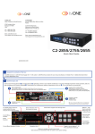


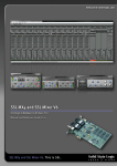
![KNA-G520 - [::] Kenwood ASC](http://vs1.manualzilla.com/store/data/006789385_1-ebacec2ef57bc4bed2b4240863ba101e-150x150.png)