1
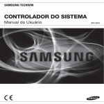
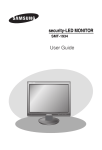
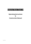
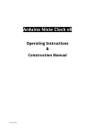
SSA-S1000 Standalone RFID Access Controller user manual imagine the possibilities Thank you for purchasing this Samsung product. To receive more complete service, please visit our website. www.samsungsecurity.com safety information CAUTION RISK OF ELECTRIC SHOCK. DO NOT OPEN CAUTION: TO REDUCE THE RISK OF ELECTRIC SHOCK, DO NOT REMOVE COVER (OR BACK) NO USER SERVICEABLE PARTS INSIDE. REFER SERVICING TO QUALIFIED SERVICE PERSONNEL. This symbol indicates that dangerous voltage consisting a risk of electric shock is present within this unit. This exclamation point symbol is intended to alert the user to the presence of important operating and maintenance (servicing) instructions in the literature accompanying the appliance. WARNING • To reduce the risk of fire or electric shock, do not expose this appliance to rain or moisture. WARNING 1. Be sure to use only the standard adapter that is specified in the specification sheet. Using any other adapter could cause fire, electrical shock, or damage to the product. 2. Incorrectly connecting the power supply or replacing battery may cause explosion, fire, electric shock, or damage to the product. 3. Do not connect multiple controllers to a single adapter. Exceeding the capacity may cause abnormal heat generation or fire. 4. Securely plug the power cord into the power receptacle. Insecure connection may cause fire. 5. When installing the controller, fasten it securely and firmly. The fall of controller may cause personal injury. 6. Do not place conductive objects (e.g. screwdrivers, coins, metal parts, etc.) or containers filled with water on top of the controller. Doing so may cause personal injury due to fire, electric shock, or falling objects. 7. Do not install the unit in humid, dusty, or sooty locations. Doing so may cause fire or electric shock. 8. If any unusual smells or smoke come from the unit, stop using the product. In such case, immediately disconnect the power source and contact the service center. Continued use in such a condition may cause fire or electric shock. 9. If this product fails to operate normally, contact the nearest service center. Never disassemble or modify this product in any way. (SAMSUNG is not liable for problems caused by unauthorized modifications or attempted repair.) 10.. When cleaning, do not spray water directly onto parts of the product. Doing so may cause fire or electric shock. CAUTION 1. Do not drop objects on the product or apply strong blows to it. Keep away from a location subject to excessive vibration or magnetic interference. 2. Do not install in a location subject to high temperature (over 50°C), low temperature (below -20°C), or high humidity. Doing so may cause fire or electric shock. 3. If you want to relocate the already installed product, be sure to turn off the power and then move or reinstall it. 4. Remove the power plug from the outlet when there is a lighting storm. Neglecting to do so may cause fire or damage to the product. 5. Keep out of direct sunlight and heat radiation sources. It may cause fire. 6. Install it in a place with good ventilation. 7. Avoid aiming the controller directly towards extremely bright objects such as sun. 2_ safety information 8. Apparatus shall not be exposed to dripping or splashing and no objects filled with liquids, such as vases, shall be placed on the apparatus. 9. The Mains plug is used as a disconnect device and shall stay readily operable at any time. FCC Statement Caution : Any changes or modifications in construction of this device which are not expressly approved by the party responsible for compliance could void the user’s authority to operate the equipment. This device complies with part 15 of the FCC Rules. Operation is subject to the following two conditions: 1) This device may not cause harmful interference, and - Reorient or relocate the receiving antenna. - Increase the separation between the equipment and receiver. - Connect the equipment into an outlet on a circuit different from that to which the receiver is connected. - Consult the dealer or an experienced radio/TV technician for help. IMPORTANT SAFETY INSTRUCTIONS 1. Read these instructions. 2. Keep these instructions. 3. Heed all warnings. 4. Follow all instructions. 5. Do not use this apparatus near water. 6. Clean only with dry cloth. 7. Do not block any ventilation openings. Install in accordance with the manufacturer’s instructions. 8. Do not install near any heat sources such as radiators, heat registers, or other apparatus (including amplifiers) that produce heat. 9. Do not defeat the safety purpose of the polarized or grounding-type plug. A polarized plug has two blades with one wider than the other. A grounding type plug has two blades and a third grounding prong. The wide blade or the third prong is provided for your safety. If the provided plug does not fit into your outlet, consult an electrician for replacement of the obsolete outlet. 10. Protect the power cord from being walked on or pinched particularly at plugs, convenience receptacles, and the point where they exit from the apparatus. 11. Only use attachments/accessories specified by the manufacturer. 12. Use only with cart, stand, tripod, bracket, or table specified by the manufacturer, or sold with the apparatus. 13. Unplug this apparatus when a card is used. Use caution when moving the cart/ apparatus combination to avoid injury from tip-over. 14. Refer all servicing to qualified service personnel. Servicing is required when the apparatus has been damaged in any way, such as powersupply cord or plug is damaged, liquid has been spilled or objects have fallen into the apparatus, the apparatus has been exposed to rain or moisture, does not operate normally, or has been dropped. English English _ 3 SAFETY INFORMATION 2) This device must accept any interference received, including interference that may cause undesired operation. NOTE: This equipment has been tested and found to comply with the limits for a Class B digital device, pursuant to Part 15 of the FCC Rules. These limits are designed to provide reasonable protection against harmful interference in a residential installation. This equipment generates, uses and can radiate radio frequency energy and, if not installed and used in accordance with the instructions, any cause harmful interference to radio communications. However, there is no guarantee that interference will not occur in a particular installation. If this equipment does cause harmful interference to radio or television reception, which can be determined by turning the equipment off and on, the user is encouraged to try to correct the interference by one or more of the following measures: contents PRODUCT INTRODUCTION 5 INSTALLATION AND EXTERNAL CONNECTION 9 SYSTEM INITIALIZATION & BASIC OPERATIONS 12 TROUBLESHOOTING 5 6 7 8 8 Feature What’s included At a Glance Cable Color Scheme Cable Selection 9 9 10 Installation Bypass Diode Connection I/O Connection 12 12 13 13 Initializing the system by short-circuiting Basic Operations To register /delete Master ID To register/delete ID card 14 TroubleShooting 15 Product Specifications 14 PRODUCT SPECIFICATIONS 15 4_ contents product introduction FEATURE ◆ 125 kHz Proximity Access Controller ◆ Up to 512 users including one Master ID can be registered ◆ Standalone (no application S/W required) ◆ Direct Control of the Door Lock ◆ Can select a lock device type from Power Fail Safe and Power Fail Secure ◆ Epoxy Molding ◆ Weatherproof English English _ 5 PRODUCT INTRODUCTION This product is designed for use with one-door access control for security applications. With its compact design, you can install this product on the wall or a doorframe; Its epoxy molding guarantees stable operation in a challenging environment. This product enables you to control the door using the user card and provides a simple method to register or delete cards, and initialize the system, which is, one of the most convenient and safest door controller. And it is also featured by the 2-color LED indicator and the internal buzzer, enabling you to easily check the current mode and operation of the door lock. product introduction WHAT’S INCLUDED Check if the following items are included in the product package. tGj Main Module Bezel Master Card (x1) Keytag (x5) xGn 3.5 x 40mm Screws (x2) 3.5 x 25mm Screws (x2) 6 x 30mm Plastic Anchors (x2) CD Manual 6_ product introduction Diode (X 2) (UF4004, 1N4001~4007) Quick Guide AT A GLANCE Front/Rear 4 5 1 LED Displays the system operation status using red and green indicators. 2 Fixing Hole Fixing hole for wall-mounting. 3 Connection Cable Used to connect to the power or I/O cable. 4 Program Port Port used to upgrade the firmware. 5 Buzzer Piezo buzzer. English English _ 7 PRODUCT INTRODUCTION 3 product introduction CABLE COLOR SCHEME Item Cable Color Signal Line Description Red DC+12V Black GND Yellow AUX INPUT#1 Blue Door Contact Sensor Green Exit Button Exit Button Connection Port Purple Alarm Out Alarm Device Connection Port White Door Lock Out +12V supplied Power Input Earth-Grounding for Power Select a Lock Type Door Sensor Connection Port Output Gray Orange Not used Brown CABLE SELECTION Item 1 2 Power (DC +12V) Belden #9409, 18 AWG 2 Conductor, Unshielded Door Contact Sensor Belden #9512, 22 AWG 4 Conductor, Shielded Exit Button Sensor Input 3 Cable Type Door Lock Alarm Device 8_ product introduction Belden #9514, 22 AWG 8 Conductor, Shielded Belden #9409, 18AWG 2 Conductor, Unshielded Door Lock device connection port installation and external connection INSTALLATION 6-32 hole 44.4 6-32 or M3 Screws 1/2” hole 40.6 6-32 hole Reader Module 8.5 - On a doorframe or the wall 1. Drill a 1/2-inch (12.7 mm) hole onto the center of the doorframe or the wall where SSA-S1000 is installed, which makes room for the cable of the reader module. 2. Drill two 0.3-inch (7.62 mm) holes: one on the point of 0.39 inch (10 mm) horizontally to the right, 1.74 inch (44.4 mm) vertically up from the center hole, and one on the point of 0.33 inch (8.5 mm) horizontally to the left, 0.3 inch (7.62 mm) vertically down from the point. 3. Insert the reader module cable into the center hole and secure the module using two screws inserted in the upper right and the bottom left corner, respectively. 4. Insert the bezel of SSA-S1000 into the reader module and attach it by pressing the upper and lower corner of the bezel. BYPASS DIODE CONNECTION If you connected an inductor (door lock or alarm device) to the output relay, there should occur a voltage surge while the inductor was between turning on and turning off. If you do not connect a reverse diode to the relay, the voltage surge will cause damage to the electric circuit of the controller. To reduce this surge, it is recommended to connect the bypass diode to the relay. English English _ 9 INSTALLATION AND EXTERNAL CONNECTION 10 installation and external connection I/O CONNECTION Input Connection DOOR CONTACT (blue) Door Contact Sensor EXIT BUTTON (green) Exit Button PUSH DC +12V GND (black) GND DC +12V (red) DC 12V(+) POWER - To connect the power supply unit 1. Connect the DC+12V to the red line. 2. Connect GND to the black line. - To connect the Door Contact Sensor 1. Connect the COM port of the sensor to the blue line. 2. Connect the NO port of the sensor with the GND line. - To connect the Exit Button 1. Connect one end of the button to the green line. 2. Connect the other end of the button to GND. 10_ installation and external connection Output Connection DOOR LOCK OUT (white) Door Lock Alarm Device Lock Type Select (yellow) Cathode Anode 1N4004 ~ 1N4007 or equiv. DC +12V GND DC 12V(+) POWER - To connect the power supply unit 1. Connect the DC+12V to the red line. 2. Connect GND to the black line. - To connect the door lock device 1. Connect the plus(+) line of the lock device to DC+12V. 2. Connect the minus(-) line of the lock device to the white line. - To connect the alarm device 1. Connect the plus(+) line of the alarm device to DC+12V. 2. Connect the minus(-) line of the alarm device to the purple line. - To specify the lock type POWER FAIL SAFE: Connect the yellow line to GND. POWER FAIL SECURE: Leave the yellow line in the floating state. English English _ 11 INSTALLATION AND EXTERNAL CONNECTION ALARM OUT (purple) system initialization & basic operations INITIALIZING THE SYSTEM BY SHORT-CIRCUITING 1. Turn off the product and short-circuit three lines: white line of the door lock device, green line of the Exit button, and yellow line of the lock type. Short-Circuit White 2. When you turn the product back on, all of the LED indicators turn red or green, repeat turning on/off twice before being completely turned off. Door Lock Green Exit Button Yellow Lock Type 3. In the power-off condition, all LED indicators turn green bottom up in sequence. 4. When you hear a beep 4 times, that indicates that the initialization is completed. Black Power M Red If you initialize the system, all of the data settings will return to the factory default. BASIC OPERATIONS When the power is supplied 1. All of the LED indicators will turn red or green, and repeat turning ON/OFF twice before being completely turned OFF. In the power-off condition, all LED indicators turn red bottom up in sequence. 2. You will hear a beep once. When you present a registered card to the product or press the Exit button 1. All LED indicators turn from red to green, and turn off top down in sequence before turning back red. 2. Then, the door stays open for the specified time with the upper two indicators turning green, which indicates the door is open. 3. You will hear a beep once. When you present an unregistered card to the product 1. All LED indicators turn red, and repeat turning on/off twice before staying in ON. 2. You will hear a beep twice. When you present a user card to the product while the door is open 1. The two LED indicators from the top stay green, indicating the door is open; in the mean time, the other indicators reflect the authentication results. 12_ system initialization & basic operations TO REGISTER /DELETE MASTER ID 1. First turn off the product, and short-circuit two lines: purple line of Alarm Out and blue line of the Door Contact Sensor. SSA-S1000 Cable Yellow Green Short-Circuit 3. Upon deletion of the Master Card, you will hear a beep once and all of the LED indicators toggle between green and red twice before turning off; in this condition, they turn red from bottom up in sequence. Purple White Red DC12V 4. When the deletion is completed, turn off the product. Connect the purple line of Alarm Out and the blue line of the Door Contact Sensor back to their original ports, respectively. Power GND Black 5. When you turn the product back on, it recognizes and registers the first-read card as the Master Card. And if you present a registered user card to the product upon deletion of the Master Card, that card will be registered as the Master Card. M If you present a registered user card after the Master Card is deleted, that card will be registered as the Master Card. TO REGISTER/DELETE ID CARD 1. If you present the Master Card to the product, it will sound the beep once and the first three LED indicators from the top will turn green from the top. SSA-S1000 MASTER CARD 2. If you present a new user card to the product, it will sound the beep once and all of the LED indicators except for the first three ones from the top will turn from red to green. Then, they all turn off and turn back on bottom up in sequence. When all of the LED indicators turn back on, they will turn red except for the first three LED indicators from the top . Then, the user card will be registered. 3. If you present a registered user card, the product will sound the beep twice and all LED indicators except for the first 3 from the top will turn red, and repeat turning on/off twice before being completely ON. Then the user card will be deleted. 4. When you present the Master Card to the product after the user card is deleted, the product will sound the beep once and all of the LED indicators turn red, starting with the first three LED indicators from the top turning from green to red. M If you present a registered user card after the Master Card is deleted, that card will be registered as the Master Card. English English _ 13 SYSTEM INITIALIZATION & BASIC OPERATIONS Blue 2. When you turn the product back on, you will hear the beep twice while all of the LED indicators turn red, and repeat turning on/off twice before being completely ON; then the Master card will be deleted. troubleshooting TROUBLESHOOTING If the product does not function properly, please see the below for trouble shooting. PROBLEM SOLUTION The user card is not deleted. 1) The Exit button does not work at all. 1) 14_ troubleshooting Check if the product works properly. - If the product works properly and you have the Master Card c Read the Master Card. d Read the card to delete. e Read the Master Card again to switch to normal mode. f For more information about deleting user cards, refer to the ID registration and deletion section in this manual. - If you lost the Master Card c Turn off the product and short-circuit the purple and blue lines, then turn the product back on. d The Master ID will be deleted with a flashing LED indicator and beep. e When the Master card is deleted, turn off the product and restore the purple and blue lines to their respective original positions. f The very first card read by the product after turning on the product will be registered as the Master Card. g For deleting the ID once the Master Card is registered, refer to the ID registration and deletion section in this manual. h Turn off the product and short-circuit the purple and blue lines, then turn the product back on. i The Master ID will be deleted with a flashing LED indicator and beep. j When the Master card is deleted, turn off the product and restore the purple and blue lines to their respective original. k The very first card read by the product after turning on the product will be registered as the Master Card. Check if the Exit button is connected to SSA-S1000 properly. (the Exit button should be used with a NO-type button) 2) Check if the Exit button works normally. - Check the connection cable between the Exit button and SSA-S1000 for any disconnection or short-circuit. - Try to connect the two lines on the Exit button. c If SSA-S1000 responds when you press the Exit button √ Replace the Exit button as it is defective. d If SSA-S1000 does not respond at all √ Initialize the product as it is damaged or malfunctions. (Initializing the product will lose all user data.) 3) If the trouble persists after following the procedures above, contact a designated service center. product specifications PRODUCT SPECIFICATIONS Item SSA-S1000 Users 512 Users Power / Current DC 12V / Max.110mA Reading Time (Card) 30ms Door Open Time 5sec. (Fixed) Input Port 3ea: Exit Button, Door Sensor, Lock Type Select [Power fail Safe / Power Fail Secure] Output Port 2ea : TR Output / DC 12V. Rating Max. 300mA Alarm Output, DC 12V. Rating Max. 1A Lock Output LED Indicator 9 LED Indicators (Red and Green) Beeper Piezo Buzzer Operating Temperature -20°C to +50°C Operating Humidity 10% to 90% Relative Humidity Non-Condensing Color / Material Silver with Black/ Polycarbonate Dimension (W x H x D(mm)) 45.0 x 122.0 x 25.0 Weight 130g Correct Disposal of This Product (Waste Electrical & Electronic Equipment) (Applicable in the European Union and other European countries with separate collection systems) This marking on the product, accessories or literature indicates that the product and its electronic accessories (e.g. charger, headset, USB cable) should not be disposed of with other household waste at the end of their working life. To prevent possible harm to the environment or human health from uncontrolled waste disposal, please separate these items from other types of waste and recycle them responsibly to promote the sustainable reuse of material resources. Household users should contact either the retailer where they purchased this product, or their local government office, for details of where and how they can take these items for environmentally safe recycling. Business users should contact their supplier and check the terms and conditions of the purchase contract. This product and its electronic accessories should not be mixed with other commercial wastes for disposal. Correct disposal of batteries in this product (Applicable in the European Union and other European countries with separate battery return systems.) This marking on the battery, manual or packaging indicates that the batteries in this product should not be disposed of with other household waste at the end of their working life. Where marked, the chemical symbols Hg, Cd or Pb indicate that the battery contains mercury, cadmium or lead above the reference levels in EC Directive 2006/66. If batteries are not properly disposed of, these substances can cause harm to human health or the environment. To protect natural resources and to promote material reuse, please separate batteries from other types of waste and recycle them through your local, free battery return system. English English _ 15 SALES NETWORK SAMSUNG TECHWIN CO., LTD. Samsungtechwin R&D Center, 701, Sampyeong-dong, Bundang-gu, Seongnam-si, Gyeonggi-do, Korea, 463-400 TEL : +82-70-7147-8740~60 FAX : +82-31-8018-3745 SAMSUNG TECHWIN AMERICA Inc. 1480 Charles Willard St, Carson, CA 90746, UNITED STATES Tol Free : +1-877-213-1222 FAX : +1-310-632-2195 www.samsungcctvusa.com www.samsungsecurity.com www.samsungtechwin.com SAMSUNG TECHWIN EUROPE LTD. Samsung House, 1000 Hillswood Drive, Hillswood Business Park Chertsey, Surrey, UNITED KINGDOM KT16 OPS TEL : +44-1932-45-5300 FAX : +44-1932-45-5325 P/No. : Z8100239401A