1
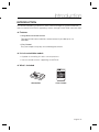
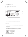
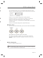
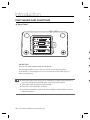
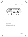
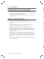
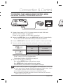
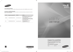
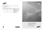
COAXIAL REMOTE CONTROLLER User Manual SPC-300 W • COAXIAL REMOTE CONTROLLER User Manual Copyright ©2009 Samsung Techwin Co., Ltd. All rights reserved. Trademark is the registered logo of Samsung Techwin Co., Ltd. The name of this product is the registered trademark of Samsung Techwin Co., Ltd. Other trademarks mentioned in this manual are the registered trademark of their respective company. Restriction Samsung Techwin Co., Ltd shall reserve the copyright of this document. Under no circumstances, this document shall be reproduced, distributed or changed, partially or wholly, without formal authorization of Samsung Techwin. Disclaimer Samsung Techwin makes the best to verify the integrity and correctness of the contents in this document, but no formal guarantee shall be provided. Use of this document and the subsequent results shall be entirely on the user’s own responsibility. Samsung Techwin reserves the right to change the contents of this document without prior notice. Warranty If the product does not operate properly in normal conditions, please let us know. Samsung Techwin will resolve the problem for free of charge. The warranty period is 3 years. However, the followings are excluded: • Data loss due to a damaged hard disk • If the system behaves abnormally because you run a program irrelevant to the system operation. • Data loss due to virus infection • Deteriorated performance or natural worn-out in process of time • Sensory phenomenon that does not affect the performance or quality of the product (ex: working noise). W 1 2 3 4 5 6 7 8 9 1 Safety information CAUTION RISK OF ELECTRIC SHOCK. DO NOT OPEN CAUTION: TO REDUCE THE RISK OF ELECTRIC SHOCK, DO NOT REMOVE COVER (OR BACK) NO USER SERVICEABLE PARTS INSIDE. REFER SERVICING TO QUALIFIED SERVICE PERSONNEL. This symbol indicates that dangerous voltage consisting a risk of electric shock is present within this unit. This exclamation point symbol is intended to alert the user to the presence of important operating and maintenance (servicing) instructions in the literature accompanying the appliance. WARNING • To reduce the risk of fire or electric shock, do not expose this appliance to rain or moisture. WARNING 1. Be sure to use only the standard adapter that is specified in the specification sheet. Using any other adapter could cause fire, electrical shock, or damage to the product. 2. Incorrectly connecting the power supply or replacing battery may cause explosion, fire, electric shock, or damage to the product. 3. Do not connect multiple controllers to a single adapter. Exceeding the capacity may cause abnormal heat generation or fire. 4. Securely plug the power cord into the power receptacle. Insecure connection may cause fire. 5. When installing the controller, fasten it securely and firmly. The fall of controller may cause personal injury. 6. Do not place conductive objects (e.g. screwdrivers, coins, metal parts, etc.) or containers filled with water on top of the controller. Doing so may cause personal injury due to fire, electric shock, or falling objects. 7. Do not install the unit in humid, dusty, or sooty locations. Doing so may cause fire or electric shock. 8. If any unusual smells or smoke come from the unit, stop using the product. In such case, immediately disconnect the power source and contact the service center. Continued use in such a condition may cause fire or electric shock. 9. If this product fails to operate normally, contact the nearest service center. Never disassemble or modify this product in any way. (SAMSUNG is not liable for problems caused by unauthorized modifications or attempted repair.) 10. When cleaning, do not spray water directly onto parts of the product. Doing so may cause fire or electric shock. English 3 Safety information CAUTION 1 1. Do not drop objects on the product or apply strong blows to it. Keep away from a location subject to excessive vibration or magnetic interference. 2 2. Do not install in a location subject to high temperature (over 50°C), low temperature (below -10°C), or high humidity. Doing so may cause fire or electric shock. 3 4 5 3. If you want to relocate the already installed product, be sure to turn off the power and then move or reinstall it. 6 4. Remove the power plug from the outlet when there is a lighting storm. Neglecting to do so may cause fire or damage to the product. 7 5. Keep out of direct sunlight and heat radiation sources. It may cause fire. 8 6. Install it in a place with good ventilation. 9 7. Avoid aiming the controller directly towards extremely bright objects such as sun. 8. Apparatus shall not be exposed to dripping or splashing and no objects filled with liquids, such as vases, shall be placed on the apparatus. 9. The Mains plug is used as a disconnect device and shall stay readily operable at any time. 1 1 Correct Disposal of This Product (Waste Electrical & Electronic Equipment) 1 (Applicable in the European Union and other European countries with separate collection systems) This marking on the product, accessories or literature indicates that the product and its electronic accessories (e.g. charger, headset, USB cable) should not be disposed of with other household waste at the end of their working life. To prevent possible harm to the environment or human health from uncontrolled waste disposal, please separate these items from other types of waste and recycle them responsibly to promote the sustainable reuse of material resources. 1 Household users should contact either the retailer where they purchased this product, or their local government office, for details of where and how they can take these items for environmentally safe recycling. 1 Business users should contact their supplier and check the terms and conditions of the purchase contract. This product and its electronic accessories should not be mixed with other commercial wastes for disposal. Correct disposal of batteries in this product (Applicable in the European Union and other European countries with separate battery return systems.) This marking on the battery, manual or packaging indicates that the batteries in this product should not be disposed of with other household waste at the end of their working life. Where marked, the chemical symbols Hg, Cd or Pb indicate that the battery contains mercury, cadmium or lead above the reference levels in EC Directive 2006/66. If batteries are not properly disposed of, these substances can cause harm to human health or the environment. To protect natural resources and to promote material reuse, please separate batteries from other types of waste and recycle them through your local, free battery return system. 4 – COAXIAL REMOTE CONTROLLER a g h nt) ms) ing. act. osal. Important Safety Instructions 1. Read these instructions. 2. Keep these instructions. 3. Heed all warnings. 4. Follow all instructions. 5. Do not use this apparatus near water. 6. Clean only with dry cloth. 7. Do not block any ventilation openings. Install in accordance with the manufacturer’s instructions. 8. Do not install near any heat sources such as radiators, heat registers, or other apparatus (including amplifiers) that produce heat. 9. Do not defeat the safety purpose of the polarized or grounding-type plug. A polarized plug has two blades with one wider than the other. A grounding type plug has two blades and a third grounding prong. The wide blade or the third prong is provided for your safety. If the provided plug does not fit into your outlet, consult an electrician for replacement of the obsolete outlet. 10. Protect the power cord from being walked on or pinched particularly at plugs, convenience receptacles, and the point where they exit from the apparatus. 11. Only use attachments/accessories specified by the manufacturer. 12. Use only with cart, stand, tripod, bracket, or table specified by the manufacturer, or sold with the apparatus. 13. Unplug this apparatus when a card is used. Use caution when moving the cart/ apparatus combination to avoid injury from tip-over. 14. Refer all servicing to qualified service personnel. Servicing is required when the apparatus has been damaged in any way, such as powersupply cord or plug is damaged, liquid has been spilled or objects have fallen into the apparatus, the apparatus has been exposed to rain or moisture, does not operate normally, or has been dropped. ms.) rm f English 5 Contents IN Introduction Introduction 6 Part names and functions 7 T a ❖ Installation Checking Installation Environment 11 Installation precautions 11 Connection & Control To Control the camera coaxial communications 12 To control the camera using RS-485 device via coaxial communications 13 To control the camera using RS-232 device via coaxial communications 14 To control the camera using RS-485 signal output 15 To control the camera using RS-485 signal output via RS-232 communications 16 Switch Setting Table 17 Specifications 6 – COAXIAL REMOTE CONTROLLER Specifications 20 Dimensions 21 ❖ ❖ Introduction INTRODUCTION This remote controller can control A1 series cameras through A1 coaxial connection, and can control COAXITRON supporting cameras through COAXITRON communication. ❖ Features • Long-distance remote control Through RS-485 communication, remote control is possible up to 1.2 kilometers. • Easy Control Easy and simple 5-way keys for controlling the camera. ❖ List of controllable models • Capable of controlling A1 series camera products. • You can control cameras supporting COAXITRON. ❖ What’s Included COAXIAL REMOTE CONTROLLER User Manual <Controller> SPC-300 <User Guide> English 7 Introduction PART NAMES AND FUNCTIONS ❖ Front Panel n o p POWER s STATUS POWER (X)1 23 23 901 (X)10 901 901 78 r 23 ON ON 1 2 1 2 3 4 5 6 7 8 TERMINATION PROTOCOL t 456 L 456 S 456 q 78 ADDRESS (X)100 ON 78 OFF CABLE COMPENSATION ❻ REMOTE CONTROLLER SPC-300 ❶ STATUS LED - Displays the status of the current operation. ❷ POWER LED - Switch to select the power source from DC 12 V or 4 AA batteries. ❸ POWER Switch - If you slide it to ON, the controller turns on. ❹ CABLE COMPENSATION Switch - For long distance coaxial communications, you can use this switch for amplifying the control signal. ❼ ❺ RS-485 TERMINATION & PROTOCOL Setting Switch - You can select to set the RS-485 termination (left 2-pin piano switch). - To set the RS-485 termination (left 2-pin piano switch), turn the switch ON. N ON ON 1 2 1 2 3 4 5 6 7 8 TERMINATION PROTOCOL 8 – COAXIAL REMOTE CONTROLLER ON ON 1 2 1 2 3 4 5 6 7 8 TERMINATION PROTOCOL - Use pin 1,2,3 of the Protocol setting switch to select a protocol. - The protocol switch pin 4 sets the protocol to COAXIAL or COAXITRON. - Use pin 5,6 of the Protocol setting switch to select a baud rate. - The protocol switch pin 7 sets the protocol to COAXIAL (BNC communication) or RS-485 output. - Use pin 8 of the Protocol setting switch to select RS-232 input. ❻ Address Switch - For RS-232 / RS-485 communications, you can use this switch to set the address. 23 901 23 901 (X)1 456 (X)10 456 23 456 78 901 ADDRESS (X)100 78 t - For multi-protocol settings, you can set the protocol (right 8-pin piano switch), baud rate, and communication mode of COAXIAL/COAXITRON/RS-485/RS-232. 78 s Introduction - Set the address by using three switches shown above. - From the left, the number is hundreds, tens and ones place, respectively. The effective range of valid address is between 0 and 255 (1~255 for multiprotocol). g ❼ Menu Navigation Key Use this to navigate through the menus. NOTE For further details on ON/OFF setting of each switch for the applicable configuration, refer to SPC-300 Connection and Control section. English 9 Introduction PART NAMES AND FUNCTIONS ❖ ❖ Rear Panel ❶ ❷ - AA BATTERY You can use 4 AA-sized batteries for the power. ❸ - The average operation time is 20 hours based on the alkaline battery. (If the battery is discharged, it can cause a distortion of the video signal, or electric interference.) ❹ NOTE Remove the battery if you do not use the controller for a longer period. Otherwise, it may cause damage to the controller from a leak of the battery solution. Take caution not to change the specified polarity. Do not use a new battery with an old one. For storing used batteries, keep out of reach of children. Wasted batteries are to be collected separately. 10 – COAXIAL REMOTE CONTROLLER ❺ Introduction ❖ Top REMOTE CONTROLLER SCP-300 TERMINATION 1 2 ON S OFF PROTOCOL 1 2 3 4 5 6 7 8 ON L CABLE COMPENSATION ADDRESS (X)100 ON (X)10 (X)1 POWER STATUS RS-232C n TX o POWER RS-485 VIDEO RX p OUT DC 12V IN q r ❶ USB Port - This terminal is used for updating the product’s firmware. ❷ RS-232 Port (9-pin D SUB) - Used to control remotely using RS-232 communication. ❸ RS-485 Port (4-pin) - Used to control remotely using RS-485 communication. ❹ VIDEO IN/OUT Connector (BNC) - VIDEO IN receives coaxial communication from cameras, and VIDEO OUT outputs the video signal. ❺ DC12V Power Connector (2-PIN) - Used for connecting DC12V power source. English 11 Installation CHECKING INSTALLATION ENVIRONMENT • Please check the following instructions before installation for your safety. T K • The way of connecting the main product with external devices (COAXIAL BNC) is very important to build up a proper system. • Do not disassemble the unit; doing so could expose you to dangerous high voltage points. INSTALLATION PRECAUTIONS • Make sure you turn off the product before installation. • Do not put a strong force on or shake the product; otherwise it may cause malfunction. 1 • Keep the product away from areas of strong magnetic field or electric interference, or wireless devices such as radio or TV set. • Keep clean the installation place during and after the installation. • An abnormal smells from the product is a sign of abnormal condition, which may cause fire or electric shock. In this case, disconnect the product from the main power immediately and contact the retailer for technical help from authorized servicing. 2 3 4 • Keep the product away from a wet floor, do not use an unearthed power extension cable, worn-out power cord, neither forget earth-grounding. • Use a dry cloth only to dirt off the product. If the product is badly dirty, apply neutral detergent on a cloth that is used to dirt off, and wipe it out with a dry cloth. • Do not use volatile substances such as alcohol, benzene or thinner as these may damage the finish. ❖ N 12 – COAXIAL REMOTE CONTROLLER Connection & Control TO CONTROL THE CAMERA USING CONTROL MENU KEYS AND COAXIAL / COAXITRON OUTPUT REMOTE CONTROLLER SCP-300 TERMINATION SCX-RD100 1 2 ON S OFF PROTOCOL 1 2 3 4 5 6 7 8 ON L CABLE COMPENSATION ON ADDRESS (X)100 (X)10 (X)1 POWER POWER STATUS 1. Connect the product to DC 12V power source or insert 4 AA-sized batteries into the battery compartment. (Power can be supplied via USB cable connection.) 2. Connect the VIDEO IN of the unit and VIDEO OUT of the AI Camera directly. – The A1 camera and SPC-300 should be directly connected to the VIDEO IN. 3. Connect VIDEO OUT of the main unit to a monitor’s video input terminal. 4. You can control camera menu after setting the switch as shown below: PIN 4 Output Selection 1 2 3 4 5 6 7 8 ON COAXITRON PROTOCOL OFF A1 COAXIAL PIN 7 Output Selection 1 2 3 4 5 6 7 8 ON COAXIAL OUT PROTOCOL OFF RS-485 OUT ON ON – Select the coaxial output by using the protocol switch pin 7. The pin 7 coaxial / RS-485 has the output priority. – To select from COAXIAL or COAXITRON, use the pin 4. ❖ You can use the menu as following : – Press and hold [ENTER]: Moves to the main menu screen. – Press [ENTER] briefly: Used to confirm the current settings. – Four Direction Keys: Used to move the cursor up/down or left/right. NOTE No address setting is required for connecting COAXIAL / COAXITRON camera and SCP-300. If not in menu control, it operates ZOOM/FOCUS function for COAXIAL output. If not in menu control, it operates PAN/TILT function for COAXITRON output. For COAXIAL control, the camera should be set to SAMSUNG-E protocol. When controlling COAXITRON menu while the menu is turned on, press and hold ENTER key to exit the menu screen. English 13 Connection & Control TO CONTROL THE CAMERA USING RS-485 INPUT AND COAXIAL / COAXITRON OUTPUT T V REMOTE CONTROLLER SCP-300 TERMINATION 1 2 ON S OFF PROTOCOL 1 2 3 4 5 6 7 8 ON L CABLE COMPENSATION ON ADDRESS (X)100 (X)10 (X)1 POWER POWER STATUS 1. Connect the product to DC 12V power source or insert 4 AA-sized batteries into the battery compartment. (Power can be supplied via USB cable connection.) 1 2. Connect the VIDEO IN of the unit and VIDEO OUT of the AI Camera directly. 2 – The A1 camera and SPC-300 should be directly connected to the VIDEO IN. 3 3. Connect VIDEO OUT of the main unit to a monitor’s video input terminal. 4. Connect TX(+/-) of RS-485 device to RX(+/-) of the main unit. (For a full duplex system, connect RX(+/-) of RS-485 device to TX (+/-) of main unit additionally.) 5. Use a combination of pin 1,2,3 of the Protocol setting switch to select a protocol. – Refer to the switch configuration table. (See page 18) 4 5 6 6. Using RS-485 device, you can control the camera menu. Each mentioned protocol may require updating the firmware from the website. NOTE By factory default, protocols of SAMSUNG-E, SAMSUNG-T and PELCO-D/P are supported. To support additional protocol, access the website to update the program. RS-232 and RS-485 communications cannot be used simultaneously. COAXIAL and COAXITRON cannot be used simultaneously. RS-485 input and COAXITRON control supports SAMSUNG-E and SAMSUNG-T protocols only, while COAXIAL control supports all protocols. For COAXIAL control, the camera should be set to SAMSUNG-E protocol. 14 – COAXIAL REMOTE CONTROLLER N TO CONTROL THE CAMERA USING RS-232 DEVICE VIA COAXIAL COMMUNICATIONS REMOTE CONTROLLER SCP-300 TERMINATION 1 2 ON S OFF PROTOCOL 1 2 3 4 5 6 7 8 ON L CABLE COMPENSATION ON ADDRESS (X)100 (X)10 (X)1 POWER POWER STATUS of Connection & Control 1. Connect the product to DC 12V power source or insert 4 AA-sized batteries into the battery compartment. (Power can be supplied via USB cable connection.) 2. Set the protocol switches 7 and 8 to ON. 3. Connect the VIDEO IN of the unit and VIDEO OUT of the AI Camera directly. – For proper data communication, the unit and AI camera should be connected directly. (If you connect a DVR or keyboard in the middle of the main unit and AI camera, bidirectional communication will not be established.) 4. Connect VIDEO OUT of the main unit to a monitor’s video input terminal. 5. Connect the RS-232 device’s cable to the RS-232 port of the main unit. 6. Using RS-232 device, you can control the camera menu. – The RS-232 device is the same as RS-485 regarding the protocol setting, but supports only the Samsung protocol. – For proper coaxial communication, AI camera should be set to Samsung protocol. Refer to the switch settings. (See page 18) RS-232 and RS-485 communications cannot be used for simultaneous input. NOTE RS-232 device control supports SAMSUNG-E protocol only. English 15 Connection & Control TO CONTROL THE CAMERA USING RS-485 OUTPUT AND CONTROL MENU KEYS T O REMOTE CONTROLLER SCP-300 TERMINATION 1 2 ON S OFF PROTOCOL 1 2 3 4 5 6 7 8 ON L CABLE COMPENSATION ON ADDRESS (X)100 (X)10 (X)1 POWER POWER STATUS 1. Connect the product to DC 12V power source or insert 4 AA-sized batteries into the battery compartment. (Power can be supplied via USB cable connection.) 1 2. Connect the RX(+/-) of the unit to the RS-485 (+/-) port of the camera. 2 3. Match the camera’s address, baud rate, and protocol to the same to those of the unit. 3 4 - For address switch, refer to the page 8. 3. Now you can control the camera by using the menus. ❖ You can use the menu as following : – Press and hold [ENTER]: Moves to the main menu screen. To exit the menu screen, press and hold the key again. 5 6 – Press [ENTER] briefly: Used to confirm the current settings. – Four Direction Keys: Used to move the cursor up/down or left/right. – Control of pan/tilt/zoom using the buttons is not supported. RS-232 and RS-485 communications cannot be used simultaneously. NOTE 5-direction key (control menu) only supports A1 camera’s menu control. 16 – COAXIAL REMOTE CONTROLLER N Connection & Control TO CONTROL THE CAMERA USING RS-485 SIGNAL OUTPUT VIA RS-232 COMMUNICATIONS REMOTE CONTROLLER SCP-300 TERMINATION 1 2 ON S OFF PROTOCOL 1 2 3 4 5 6 7 8 ON L CABLE COMPENSATION ON ADDRESS (X)100 (X)10 (X)1 POWER POWER STATUS 1. Connect the product to DC 12V power source or insert 4 AA-sized batteries into the battery compartment. (Power can be supplied via USB cable connection.) 2. Set the protocol switch 8 to ON. 3. Connect the RX(+/-) of the unit to the RS-485(+/-) port of the camera. 4. Match the camera’s address, baud rate, and protocol to the same to those of the unit. – RS-232 device control supports SAMSUNG-E protocol only. 5. Connect the RS-232 device’s cable to the RS-232 port of the main unit. 6. Using RS-232 device, you can control the camera menu. RS-232 and RS-485 communications cannot be used for simultaneous input. NOTE For the switch settings, see the switch setting table. (See page 18) Input of video signal is required to control RS-485. English 17 Connection & Control SWITCH SETTING TABLE ❖ Use a combination of pin 1,2,3 of the Protocol setting switch to select a protocol. ON ON 1 2 1 2 3 4 5 6 7 8 TERMINATION PROTOCOL Protocol Setting Switch (0 :r, 1 :q) Protocol HALF/FULL Software Type (A, B, C, D) PIN 1 PIN 2 PIN 3 0 0 0 SAMSUNG-E HALF ALL 1 0 0 SAMSUNG-E FULL ALL 0 1 0 SAMSUNG-T SIMPLEX A 1 1 0 SAMSUNG-T FULL A 0 0 1 PELCO-D SIMPLEX A 1 0 1 PELCO-D FULL A 0 1 1 PELCO-P SIMPLEX A 0 0 1 PANASONIC HALF B 1 0 1 PANASONIC FULL B 0 0 1 HONEYWELL SIMPLEX C 1 0 1 HONEYWELL FULL C 0 0 1 VICON HALF D 1 0 1 VICON FULL D 0 1 1 AD SIMPLEX D 1 1 1 AD FULL D ❖ Use pin 4, 7 and 8 of the Protocol setting switch to set the coaxial output. PIN 4 Output Selection 1 2 3 4 5 6 7 8 ON COAXITRON PROTOCOL OFF A1 COAXIAL ON PIN 7 Output Selection 1 2 3 4 5 6 7 8 ON COAXIAL OUT PROTOCOL OFF RS-485 OUT PIN 8 RS-232 input ON ON 1 2 3 4 5 6 7 8 ON RS-232 input PROTOCOL OFF RS-232 No use Setting of the PIN 7 overrides that of PIN 4. NOTE 18 – COAXIAL REMOTE CONTROLLER Connection & Control – See the following table to set the baud rate. ON ON 1 2 1 2 3 4 5 6 7 8 TERMINATION PROTOCOL BAUD RATE PIN 5 PIN 6 38400 BPS OFF OFF 19200 BPS ON OFF 9600 BPS OFF ON 4800 BPS ON ON t. English 19 Specifications SPECIFICATIONS D Item Description Communication Method COAXIAL / COAXITRON INTERFACE Range Max. 500m (with 5C-2V cable) Connector Type D-SUB 9P COAXIAL Port 1 Port BAUD RATE 4800/9600/19200/38400bps (Only Samsung protocol supported) Connector Type 4P Terminal Type RS-232 Port 1 Port BAUD RATE 4800 / 9600 / 19200 / 38400 bps RS-485 USB PORT(USB2.0) S/W PROGRAM UPLOAD Composite Video 1.0Vp-p, 75ohm, VIDEO IN/OUT Cable Compensation out (Select:S/L) A) SAMSUNG-E, SAMSUNG-T, PELCO-D/P Multi-protocol (Supports 4 programs) B) SAMSUNG-E, PANASONIC C) SAMSUNG-E, HONEYWELL D) SAMSUNG-E, VICON, AD Environmental Conditions Operating Temp. -10˚C ~ +50˚C Humidity Less than 90% POWER DC12V ± 10% DIMENSIONS (WxHxD) WEIGHT 150(W) X 36(H) X 102(D) NET 20 – COAXIAL REMOTE CONTROLLER 200 g Specifications DIMENSIONS Unit (mm) English 21 SALES NETWORK SAMSUNG TECHWIN CO., LTD. Samsungtechwin R&D Center, 701, Sampyeong-dong, Bundang-gu, Seongnam-si, Gyeonggi-do, Korea, 463-400 TEL : +82-70-7147-8740~60, FAX : +82-31-8018-3745 SAMSUNG TECHWIN AMERICA Inc. 1480 Charles Willard St, Carson, CA 90746, UNITED STATES Tol Free : +1-877-213-1222, FAX : +1-310-632-2195 www.samsungcctvusa.com www.samsungtechwin.com www.samsungsecurity.com SAMSUNG TECHWIN EUROPE LTD. Samsung House, 1000 Hillswood Drive, Hillswood Business Park Chertsey, Surrey, UNITED KINGDOM KT16 OPS TEL : +44-1932-45-5300, FAX : +44-1932-45-5325 AB68-00857A P/NO. : Z6806-1331-01A