1
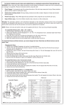
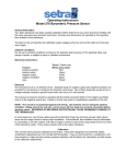
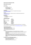
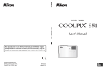
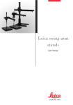
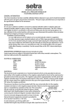
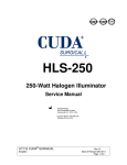
Fiber-Lite
®
DC950 ILLUMINATOR
A PRODUCT OF DOLAN-JENNER INDUSTRIES
Operation Manual
Setup
Voltage Selection:
The DC950 illuminator has universal AC voltage input. Connect the appropriate AC line cord to the
DC950 and connect to an AC power receptacle. The DC950 can operate with line voltages from 100 to 230
VAC and at 50 Hz. or 60 Hz.
Fiber Optic Connection
Notice: Do not operate the illuminator without the fiber optic connected to the illuminator.
Loosen the fiber optic nosepiece thumbscrew.
Insert the fiber optic into the illuminator nosepiece.
Tighten the thumbscrew by hand to make a secure connection to the fiber optic. Use of pliers or
other tools is not recommended.
Two nosepiece styles are available with the DC950 series of fiber optic illuminators. A-type with a
0.985 in. (25mm) ID, or B-type with a 0.590 in. (15mm) ID smaller than the 0.985 in. ID.
A-type nosepieces require the use of adapters to mate fiber optic light guides smaller than the 0.985 in. ID.
Adapters fit into the nosepiece and reduce the ID to accept the chosen fiber optic. The fiber optic and the
adapter are secured with the thumbscrew. The following A-type adapters (SX-5, SX-6 & SX-7) are made
with an idler which allows quick disconnect of the fiber optic.
B-Type nosepieces will accept self-supporting goosenecks (EEG2823C, EEG3922C, BG2820C, etc.) and
ringlight (A3739B) fiber optics without the need for an adapter. Fiber optics smaller than the 0.590 in.
(15mm) ID will require the use of B-type adapters (SX-5B, SX-6B & SX-7B).
©2004 Dolan-Jenner Industries, 159 Swanson Rd., Boxborough, MA 01719
978-263-1400, FAX: 978-264-0292, 1-800-83-FIBER, http://www.dolan-jenner.com 05-530018-0000 Rev. F 10/06
Fiber-Lite
®
Operation
Insert the power cord into the power entry module at the rear of the illuminator. Next, insert the power
cord into a 3 wire grounded AC power receptacle. Use only approved power cord supplied with the
illuminator.
Press the ON(1)/OFF(0) rocker switch on the front panel to ON(1). The illuminator will light and is ready
for service.
Lamp Intensity Control:
All the DC950 series illuminators are equipped with a front panel manual solid state intensity control
and an external interface (9-pin, D style connector) for remote intensity control via a 0-5 VDC signal on
the back panel.
Manual:
The illuminator intensity is controlled by the rotary control located on the front panel of the
illuminator. The 0 position (when control is turned fully counter-clockwise) corresponds to the lowest
illuminator intensity. The 100 position (when control is turned fully clockwise) corresponds to the highest
illuminator intensity.
NOTE: Continuous operation of the illuminator at the highest intensity level will yield rated lamp life.
Operating the illuminator at reduced intensity can result in significantly extended lamp life.
Remote Interface
Connector
w/Filtered Connector
Local / Remote Selector Switch
Voltage Selector Switch
& Fuseholder
3.15A 5x20mm
Slow Blow
Remote Interface:
The DC950 has been supplied with a filtered 9 position D-Sub connector to reduce noise that might occur
when connecting external equipment to the remote interface. Removal of this connector is not recommended
as undesired noise may occur on connections to the remote interface.
To enable the remote interface, move the LOCAL/REMOTE, located on the rear panel of unit, to the
REMOTE position. When the switch is in the REMOTE position the front panel intensity control is not
active. See Fig. 1 for the Pin Functions on the 9 Pin D-Sub connector. If the Remote Intensity Control Pin is
not connected, the illuminator will run at the maximum intensity setting until the Remote Intensity Control
Pin is connected.
2
DOLAN-JENNER INDUSTRIES, 159 Swanson Rd., Boxborough, MA 01719, U.S.A., 978-263-1400, FAX: 978-264-0292
Fiber-Lite
®
Remote Intensity Control:
The Remote Intensity Control is located on Pin 3 of the Remote Interface. When the LOCAL/REMOTE switch
is in the REMOTE position the intensity is controlled by the signal applied to Pin 3. NOTE: The front panel
intensity control is deactivated in remote mode.
The input signal must be limited to a 0 to +5 volt DC signal. A negative voltage or a voltage in excess of 5 volts
will cause the lamp to run at maximum intensity potentially shortening lamp life. The DC950 Remote Intensity
control is highly linear. At 0 volts the lamp voltage is 0 volts. At +5 volts the lamp voltage is the maximum
voltage for the lamp specified at the time the order was placed. A 2.5 volt input signal will cause the lamp to
run at 50% of lamp voltage. Refer to Table A for intermediate values.
Pin 1 can be used to supply power to a remote potentiometer. Connect the potentiometer as shown in Figure 2.
The 500 ohm series resistor prevents shorting the power supply on Pin 1 if the potentiometer should fail as a
short circuit. In all cases the minimum resistance between Pin 1 and common ground (Pins 2 and 7) must be at
least 500 ohms to prevent damage to the Pin 1 power supply.
The user may also use a fixed voltage divider to control the illuminator at a non-varying intensity level. Refer
to Figure 3 and the resistance values in Table A for sample resistor values and the corresponding lamp intensity
levels. In all cases, the minimum total resistance value connected between Pin 1 and common ground (Pins 2
and 7) must be 500 ohms (RA + RB > 500 ohms.)
Remote On-Off:
The lamp power can be controlled via Pin 6, see Fig 4. By connecting
Pin 6 to a logic high (+5v) signal(Pin 1) the lamp power will be
interrupted for as long as Pin 6 is connected to logic high. When the
contacts connecting Pin 6 are opened, removing the +5v from Pin 6,the
illuminator will return to the intensity level set by the signal connected
to Pin 3 or to the intensity level set by the front panel control. The
response time of the illuminator going from On to Off and Off to On is
dependent on the thermal response of the lamp. The lag time of the lamp
may be several hundred milliseconds from the time the Remote On-Off
signal is applied to the time the lamp attains either the full On or full Off
state. The response time of the power supply is less than 100
milliseconds.
Pin # - Signal
1
+5 VDC at 10mA max.
3
0 - 5 V (+) input
2, 7
0 - 5 V (-) input (common
ground)
6
Remote On (Open) Off (+5V)
8
Chassis ground
(shield)
9
Lamp Fail
4,5
Pin 1
+5v
Lamp
Power Off
Lamp
Power On
Pin 6
Fig 4
5
9
8
7
6
4
3
2
1
Future
Fig. 1
DOLAN-JENNER INDUSTRIES, 159 Swanson Rd., Boxborough, MA 01719, U.S.A., 978-263-1400, FAX: 978-264-0292
3
Fiber-Lite
®
Table A
RA = 500W
Voltage VDC
(Pin 3)
RA (W
)
RB (W
)
Pin 1
RB = 50kW
potentiometer
Pin 3
Pin 2
Fig. 2
% @ Full Intensity
Pin 1
+5
RA
20K
20K
20K
20K
20K
20K
13K
8.6K
5.0
4.5
4.0
3.5
3.0
2.5
2.0
1.5
2.2K
5K
8.6K
13K
20K
20K
20K
100%
90%
80%
70%
60%
50%
40%
30%
Pin 3
RB
Pin 2
Fig. 3
PIN 9
47 W
10K
Lamp Fail Ckt.
Fig. 5
Lamp Fail Signal:
A signal indicating that the lamp has failed is available on Pin 9. This signal is open collector (see Fig 5). The
user must supply the necessary circuitry to connect the lamp out signal to a signaling device. The maximum
current through the circuit is 10 mA. When the signal at Pin 9 is logic High(5v) the lamp has failed.
The Lamp Fail signal will detect if current has stopped flowing to the lamp while the intensity control signal is
not at 0 volts, the illuminator On-Off switch is in the On position and the Remote On-Off signal is in the On
condition. The Lamp Fail signal will also indicate if the lamp is not properly seated after a lamp change or if the
lamp power connector is not properly connected after a lamp change or if the lamp socket was replaced.
4
DOLAN-JENNER INDUSTRIES, 159 Swanson Rd., Boxborough, MA 01719, U.S.A., 978-263-1400, FAX: 978-264-0292
Fiber-Lite
®
WARNING
Risk of electrical shock.
Remove power plug before lamp
replacement and wait for
hot lamp to cool.
LAMP MODULE REPLACEMENT
1. Turn the illuminator intensity control fully counterclockwise (the 0 position) and run the illuminator with the
fan for several minutes. Wait until the nosepiece is cool to the touch. Press the ON(1)/OFF(0) rocker switch
to the OFF(0) position.
2. Remove the AC line cord from the AC power receptacle.
3. Release lamp module from the power supply by turning both retaining screws counterclockwise using a
straight blade screwdriver. NOTE: Both retaining screws will be disengaged from the power supply, but will
remain in place in the lamp module.
4. Remove the lamp module from the power supply by slowly pulling outward.
5. Release the lamp module by unlatching the quick disconnect lamp cord. See Fig 6.
6. Attach new lamp module by connecting the quick disconnect lamp cord.
7. Insert lamp module into power supply. Make sure lamp cord does not interfere.
8. Secure lamp module by tightening the (2) retaining screws
5. Release the lamp module by unlatching the quick disconnect lamp cord. See Fig 6.
6. Attach new lamp module by connecting the quick disconnect lamp cord.
7. Insert lamp module into power supply. Make sure lamp cord does not interfere with housing.
8. Secure lamp module by tightening the (2) retaining screws clockwise.
9. Reattach AC line cord and the illuminator is ready for service.
LAMP MODULE
Fig 6
LAMP BRACKET
LAMP
QUICK DISCONNECT LAMP CORD
LAMP SOCKET
DOLAN-JENNER INDUSTRIES, 159 Swanson Rd., Boxborough, MA 01719, U.S.A., 978-263-1400, FAX: 978-264-0292
5
Fiber-Lite
®
WARNING
Risk of electrical shock.
Remove power plug before lamp
replacement and wait for
hot lamp to cool.
LAMP REPLACEMENT
1. Follow steps 1-4 of Lamp Module Replacement.
2. Check the lamp assembly to verify that the lamp and socket are cool before proceeding.
3. Lift and remove the lamp from the lamp holder by grasping the rear of the lamp adjacent to the lamp socket.
4. Remove the lamp from the socket by holding the lamp socket and gently pulling the lamp reflector.
5. Discard the lamp.
6. Insert the replacement lamp into the lamp socket. CAUTION: Do not touch the interior of the lamp reflector, the
lamp envelope or the lamp pins with your fingers. Touching the interior of the lamp reflector, the lamp envelope
or the lamp pins will result in significant shortening of the lamp life. Handle the lamp only by the exterior of the
reflector or the area adjacent to the pins.
7. Insert the replacement lamp and socket into the lamp holder.
8. Follow steps 7-9 of Lamp Module Replacement.
WARNING
Replace the fuse with the correctly
rated fuse as listed on the label
on the back of the illuminator. Use of
an improper fuse can create
a hazardous situation.
FUSE REPLACEMENT
1. Press the ON(1)/OFF(0) switch to the OFF(0) position.
2. Remove the AC line cord from the AC power receptacle.
3. Remove the AC line cord from the power entry module at the rear of the illuminator. The fuse drawer is part of
the power entry module. The drawer is located directly beneath where the AC line cord plugs in.
4. Pull out the fuse drawer. Remove the blown fuse that is positioned closest to the illuminator and discard. The
second fuse is the spare.
5. Place the replacement fuse into the fuse drawer. The fuse will work in either orientation.
6. Push the fuse drawer until it "clicks" into position.
7. Attach the AC line cord to power entry module at the rear of the illuminator. The illuminator is now ready for
service.
6
DOLAN-JENNER INDUSTRIES, 159 Swanson Rd., Boxborough, MA 01719, U.S.A., 978-263-1400, FAX: 978-264-0292
Fiber-Lite
®
Cleaning:
If necessary wipe exterior surfaces only with a soft cloth. Do not use fluids to clean the exterior of the
illuminator. Under no circumstances allow fluids of any kind to enter the illuminator.
Replacement Parts
Part No.
686009-02770
686009-02468
686009-02787
686009-02470
686009-02712
686009-03164
Description
Quick Disconnect Lamp Socket
Lamp, EKE, 21V, 150 Watt
Fuse, 3.15A, 5 x 20, 250 V, slow blow
Lamp, EJV, 21V, 150 Watt
Lamp, EJA, 21 V, 150 Watt
Lamp, EKE-X, 21V, 150 Watt
Only above parts are replaceable. Return illuminator to factory for warranty service. Attempts to replace other parts voids warranty.
PERFORMANCE STATEMENT
Dolan-Jenner Industries, Inc. (DJI) recognizes that its illuminator products may be used under an almost
unlimited variety of conditions. As such, we are prepared to assist the customer in the selection and application of
any of these products. This includes application engineering, sample testing and other means as determined by
DJI.
Where DJI has made specific recommendations for its products, systems, or detection techniques (based on
complete and detailed information furnished by the customer) we will extend every effort to assure that the
customer is satisfied with the performance of our products. Continual development and improvement of DJI
products may require changes in details that do not coincide with descriptions or illustrations shown. All fiber
optic bundle diameters are nominal.
TWO YEAR WARRANTY ON LIGHT SOURCES
Dolan-Jenner Industries, Inc. (DJI) warrants its products to be free from defective material and
workmanship. Any light source or parts thereof which are determined by DJI to be defective within two(2) years
(average product life cycle) from shipment date will be replaced or repaired at our option. All fiber optics are
warranted for one year. This warranty specifically excludes; incandescent and quartz-halogen lamps, lamp
sockets and optical filters.
Any products which, in our opinion, have been subjected to misuse, incorrect wiring, or where installation
procedures are not in accordance with the instruction manual, are excluded from this warranty. Nor does this
warranty extend to products on which repairs or alterations have been made outside the factory, or on which the
identification or serial number has been altered or to accessories not of our manufacture.
Our obligation with respect to products or parts covered by this warranty shall be limited to repair or
replacement, F.O.B., Boxborough, Massachusetts. In no event shall DJI be held liable for consequential or special
damages, or for transportation, installation, adjustment, or other expenses which may arise in connection with
such products or parts. This warranty is in lieu of all other statements or warranties or guarantees, written or
implied, by DJI or its authorized representatives.
Important: Please contact factory for a return authorization number prior to shipping merchandise to factory.
DOLAN-JENNER INDUSTRIES, 159 Swanson Rd., Boxborough, MA 01719, U.S.A., 978-263-1400, FAX: 978-264-0292
7
Fiber-Lite
®
TECHNICAL DATA________________________________
Lamp
Voltages
Power Consumption
Lamp Life
Fuse
Color Temperature
Noise Level
Safety Approvals
Dimensions
Weight
Max. Housing Temp.
150 W Quartz halogen, 21V (EKE)
100 to 230 VAC, 50 / 60 Hz
200 W
200-10,000 Hours (EKE) depending on intensity used.
3.15 Amp, 250V, time delay, 5 x 20 mm
3250° Kelvin .
Approximately 21 dB (A)
UL/c-UL, CE (230 VAC)
4.6 H x 7.25 W x 9.5 D (inch)
11.7 H x 18.4 W x 24.3 D (cm)
12 lbs. (5.5 kg.)
15°C above ambient
Environmental Conditions Use Specifications
Type of Use
Indoor at max. altitude of 2,000 M
Installation Category
II
Temperature Range
5°C to 35°C
Relative Humidity
80% maximum up to 31° C decreasing linearly to 50% relative humidity @ 35° C
Pollution Degree
2
NOTICE: if the equipment is used in a manner not specified by the manufacturer, the protection
provided by the equipment may be impaired.
Corporate Headquarters and Factory:
Setra Systems, Inc.
159 Swanson Rd.
Boxborough, MA 01719, USA
Telephone: 800-833-4237 or 978-263-1400
Fax:
978-264-0292
Web:
www.dolan-jenner.com
e-mail: [email protected]
Setra Systems, Inc.
159 Swanson Rd.
Boxborough, MA 01719 USA
8 DOLAN-JENNER INDUSTRIES, 159 Swanson Rd., Boxborough, MA 01719, U.S.A., 978-263-1400, FAX: 978-264-0292