1
Fiber-Lite
®
Remote Intensity Control:
The Remote Intensity Control is located on Pin 3 of the Remote Interface. When the LOCAL/REMOTE switch
is in the REMOTE position the intensity is controlled by the signal applied to Pin 3. NOTE: The front panel
intensity control is deactivated in remote mode.
The input signal must be limited to a 0 to +5 volt DC signal. A negative voltage or a voltage in excess of 5 volts
will cause the lamp to run at maximum intensity potentially shortening lamp life. The DC950 Remote Intensity
control is highly linear. At 0 volts the lamp voltage is 0 volts. At +5 volts the lamp voltage is the maximum
voltage for the lamp specified at the time the order was placed. A 2.5 volt input signal will cause the lamp to
run at 50% of lamp voltage. Refer to Table A for intermediate values.
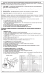
Pin 1 can be used to supply power to a remote potentiometer. Connect the potentiometer as shown in Figure 2.
The 500 ohm series resistor prevents shorting the power supply on Pin 1 if the potentiometer should fail as a
short circuit. In all cases the minimum resistance between Pin 1 and common ground (Pins 2 and 7) must be at
least 500 ohms to prevent damage to the Pin 1 power supply.
The user may also use a fixed voltage divider to control the illuminator at a non-varying intensity level. Refer
to Figure 3 and the resistance values in Table A for sample resistor values and the corresponding lamp intensity
levels. In all cases, the minimum total resistance value connected between Pin 1 and common ground (Pins 2
and 7) must be 500 ohms (RA + RB > 500 ohms.)
Remote On-Off:
The lamp power can be controlled via Pin 6, see Fig 4. By connecting
Pin 6 to a logic high (+5v) signal(Pin 1) the lamp power will be
interrupted for as long as Pin 6 is connected to logic high. When the
contacts connecting Pin 6 are opened, removing the +5v from Pin 6,the
illuminator will return to the intensity level set by the signal connected
to Pin 3 or to the intensity level set by the front panel control. The
response time of the illuminator going from On to Off and Off to On is
dependent on the thermal response of the lamp. The lag time of the lamp
may be several hundred milliseconds from the time the Remote On-Off
signal is applied to the time the lamp attains either the full On or full Off
state. The response time of the power supply is less than 100
milliseconds.
Pin # - Signal
1
+5 VDC at 10mA max.
3
0 - 5 V (+) input
2, 7
0 - 5 V (-) input (common
ground)
6
Remote On (Open) Off (+5V)
8
Chassis ground
(shield)
9
Lamp Fail
4,5
Pin 1
+5v
Lamp
Power Off
Lamp
Power On
Pin 6
Fig 4
5
9
8
7
6
4
3
2
1
Future
Fig. 1
DOLAN-JENNER INDUSTRIES, 159 Swanson Rd., Boxborough, MA 01719, U.S.A., 978-263-1400, FAX: 978-264-0292
3