1
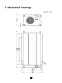
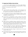
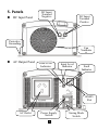
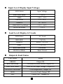
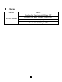
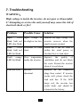
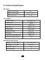
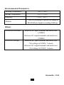
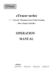
User’s Manual Before using the inverter, you need to read and save the safety instructions. STI 300-12-220 Power Frequency Pure Sine Wave Inverter The information presented in this document does not form part of any quotation or contract, is believed to be accurate and reliable and may be changed without notice. TABLE OF CONTENTS 1. Introduction ................................................... 1 2. Mechanical Drawings .................................... 2 3. Important Safety Instructions ........................ 3 4. Inverter Operation ......................................... 5 5. Panels ............................................................. 6 6. Functions ....................................................... 9 7. Troubleshooting ........................................... 12 8. Maintenance ................................................ 13 9. Technical Specification ............................... 14 1. Introduction Thanks for purchasing our company’s inverter of STI series. The product is a sine wave power frequency inverter which can convert 24V DC to 220V AC 50Hz based on full digital and intelligent design. It features high reliability, high efficiency, concise outline, small volume, full protection functions, easy installation and operation. The inverter can be applied in many fields especially for solar photovoltaic power system. Complete isolation-type inverter technology, noiseless sine AC voltage of output Adoption of advanced SPWM technology, pure sine wave output Dynamic current loop control technology to ensure inverter reliable operation Saving mode for selection Wide DC input voltage range Excellent EMC design Low output harmonic distortion(THD≤3%) LED indicators for input voltage range, load power range, normal output & failure state Input polarities conversed, load short-circuit, overload, under/over input voltage and over-temperature protections and alarms, inverter’s inner fault protections Fitted for many kinds of AC loads such as household appliances, electric tools and industrial devices Wide working temperature range (industrial level) 1 2. Mechanical Drawings (Units: mm) 2 3. Important Safety Instructions As an AC power supply equipment, the inverter’s output voltage is with the same level as that of household power plug. Mind the AC output terminals, or you may get an electric shock! Attentions: Connect the DC input according strictly to the requirement. The power inverter has a relatively wide input range, but too high or too low input may cause problems even destroy the inverter. Do not expose the inverter to humid, flammable, explosive or dust environment. Do not install the inverter in airproof location and keep enough space around the inverter. Inverter input is recommended to connect to battery. If for testing purpose, user should select DC power supply current at least twice greater than that of the inverter rated input to keep inverter normal operation. Make sure the air ventilation clearance around the inverter is more than 10cm, for when the inverter works continuously its surface may became very hot. Keep away from the material or device which may suffer from high temperature when the inverter is working. Connect the load devices to the AC output outlet or terminals, then the DC input. Make sure both the input and output connects are correct, switch on the inverter first and then turn on the load. Do not connect the battery charger or similar devices to the input terminal of the inverter. Do not put the inverter close to the open lead-acid battery because the sparkle in the terminals may ignite the hydrogen released by the battery. 3 Do not attempt to repair the fault inverter yourself, otherwise it may lead to a serious accident. Please connect the manufacture’s engineer. 4 4. Inverter Operation Connect the input and output terminals accurately by referring to the previous chapter. Use the ON / OFF switch on the front panel to turn the power on. Turn AC loads on one by one after the output of the inverter is normal, in order to prevent protections resulted from the surge power. Set the power switch to the ‘OFF’ position. Insert the load’s plug into the inverter’s output outlet, or cables to the output terminals. Connect the battery (‘+’ terminal with red line, ‘-’with black line). Do not connect them by contraries, or it will damage the power inverter. Switch the inverter to ON and then turn the loads on one by one. Check the operation state of both power inverter and loads. ‘Green’ of the LED indicator means the state is normal. If there are different loads, it is suggested that turn on the load with large startup current first, such as television, then turn on the load such as lamp when the inverter works stable. If the failure LED indicator is ‘Red’ and the buzzer alarms or no output when you turn on devices, switch off the loads and power inverter immediately. Check the system by referring to the troubleshooting guide. Turn on the devices again according to the operation methods after the failure is removed. 5 5. Panels DC Input Panel DC Input Terminal Negative DC Input Terminal Positive Protective Grounding Fan Ventilatio n AC Output Panel Load Level Indicator Input Level Indicator Fault Indicator RS485 Port AC Outlet Power Supply Switch 6 Saving Mode Switch Input Level: Display Input Voltages LED Status Input Voltage RED Slow Blink <10.5V RED 10.5~11 V ORANGE 11~12 V GREEN 12~14.5V ORANGE Fast Blink 14.5~16 V >16 V RED Fast Blink Load Level: Display AC Loads LED Status AC Load ORANGE <60 VA GREEN 60VA~225 VA RED >225 VA RED Slow Blink Overload RED Fast Blink Short Circuit Output & Fault Status LED Status Status GREEN Output Ok RED Fast Blink Overload or Short circuit, Output Off RED Slow Blink Over or Low input voltage, Output Off ORANGE Fast Blink Over temperature, Output Off RED Inverter Fault, Output Off OFF Power Off,Output Off 7 Alarms Alarms Status Overload or Short circuit, Output Off Buzzer Sounds Over or Low input voltage, Output Off Over temperature, Output Off Inverter Fault, Output Off 8 6. Functions Protections Output Short Circuit Protection The inverter switches off the output immediately when the connecting load is short. Then it recovers the output automatically after delaying 5 seconds for the first time, 10 seconds for the second time, and 15 seconds for the third time. If the short circuit status still remains when the inverter tries to recover for 3 times, you should clear the load faults then restart the inverter manually. Overload Protection When the load power is 1.25-1.5 times, 1.5-2 times and 2 times more than the rated value, the inverter will switch off the output after working for 60 seconds, 10 seconds and 1.5 seconds, respectively. Once the load power is over 230% of rating, the inverter recognizes it as AC short circuit and auto-switches off the output. If the overload status still remains when the inverter tries to recover for 3 times, you should reduce the loads then restart the inverter manually. Input Low Voltage Protection The output is switched off when the input voltage is lower than 10.5 V, and the output is auto-switched on when the input voltage recovers to 13 V. User can also manually restart the inverter to 9 switch on output by the ‘ON/OFF switch’, when the input voltage recovers to 10.5 V. Input Over Voltage Protection The output is switched off when the input voltage is higher than 16 V, also the output is auto-switched on when the input voltage drops to 15 V. Fault Protection The inverter will shut down when the output voltage is error or when the inverter has inner fault. Over Temperature Protection The inverter will shut down when the ambient temperature exceeds the normal level. And it will be back to work when the temperature recovers to the normal level. Others Saving Mode Inverter will perform the ‘saving function’, if the saving mode switch is transferred to ‘saving’ side. It means that inverter shuts down the output provided the loads value is less than 20VA. It cycles as below: the output restarts after delaying 20 seconds, and the inverter decides to remain output when the load is more than 10 20VA or to shut down output again when the load is less than 20VA. It is recommended to disable the ‘saving function’ if your loads is less than 20VA. 11 7. Troubleshooting WARNING: High voltage is inside the inverter, do not open or disassemble it! Attempting to service the unit yourself may cause the risk of electrical shock or fire! Problem Possible Cause Solution Input LED blink, fault red LED slow blink Input voltage is too high or too low Measure the input voltage. The inverter recovers when the input becomes normal. Load LED blink, fault red LED fast blink Overload or load short Check out if the AC load is within the rated power or whether there is load short. Fault orange LED fast blink Over temperature inside the inverter Improve the quality of ventilation and do not block the vents. Restart the inverter when it is cool down. Fault red LED Inverter abnormal Remove all the connected plugs then restart. If inverter works well, please check the load and line. If the LED keeps red, the inverter has inside faults and should be returned to the factory 12 8. Maintenance You must do regular proper maintenance on inverter. You should clean the cover regularly with a cloth to prevent accumulation of dust and dirt, tighten the screws on the DC input terminals. The warranty period of this product is one year from the date of original purchase. This limited warranty is void if the unit is abused, modified, installed improperly, or had its housing removed. The manufacture is not liable for damages arising from the use, misuse, or operation of this product. During the warranty period, defective units will be repaired or replaced (with the same or a comparable model). Please properly keep the maintenance card for after-sale service. 13 9. Technical Specification DC Input Input Rated Voltage 12V Input Voltage Range 10.5 ~ 16VDC ≤5W No-Load Power AC Output Output Voltage AC 220V±3% ≥240W Rated Power Maximum Short Time Power 450VA; 10s Surge Power 600VA; 1.5s Output Mode Single phase Output Waveform Sine wave Frequency 50±0.5% Hz THD≤ 3% Output Waveform Distortion ≥81% Efficiency at Rated Power Mechanical Parameters Exterior(L*W*H mm) 314.5×166×100.8 Installation(L*W mm) 200×154 Hole Size(mm) R4 Net weight (kg) 5.3 14 Environmental Parameters Working Temperature -20℃~+50℃ Storage Temperature -35℃~ +70℃ Humidity < 95%(N.C.) Altitude < 5000 m (Derating to operate according to IEC62040 at a height exceeding 1000 m) Others Insulation Resistance Between DC input terminals and metal case: ≥550MΩ; Between AC output terminals and metal case: ≥550MΩ. Dielectric Strength Between DC input terminals and metal case: Test voltage AC1500V, 1 minute Between AC output terminals and metal case: Test voltage AC1500V, 1 minute Version No. : V1.0 15 BEIJING EPSOLAR TECHNOLOGY CO., LTD. Tel: +86-10-82894112 / 82894962 Fax: +86-10-82894882 E-mail: [email protected] Website: http://www.epsolarpv.com/