1
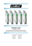
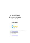
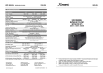
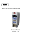
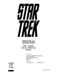
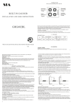
User’s Manual Before using the inverter, you need to read and save the safety instructions. SH 400 / SH 600 / SH 1000 Pure Sine Wave Inverter The information presented in this document does not form part of any quotation or contract, is believed to be accurate and reliable and may be changed without notice. TABLE OF CONTENTS 1. Introduction ................................................... 1 2. Mechanical Drawings .................................... 2 3. Important Safety Instructions ........................ 5 4. Inverter Operation ......................................... 6 5. Function ......................................................... 7 6. Troubleshooting ........................................... 13 7. Maintenance ................................................ 14 8. Technical Specification ............................... 15 1. Introduction Thanks for purchasing our company’s power inverter of SH series . The product is a sine wave power inverter which can convert 12V/24V/48V DC to 220V AC (50Hz/60Hz) based on high performance DSP full digital and intelligent design. It has the features of high reliability, high efficiency, low weight, small volume, full protection functions, easy installation and operation. The inverter can be applied in many fields especially for solar photovoltaic power system. Powerful DSP digital and intelligent design Wide DC input voltage range Pure sine wave output with high efficiency and stability Excellent EMC design Low output harmonic distortion(THD≤3%) Two on-off control mode: local main switch and remote control switch LED indicators for input voltage range, load power range, normal output & failure state Load short-circuit, overload, input voltage under/over and over-temperature protections and alarms, inverter’s inner fault protections. RS-232 communication interface connecting with PC or other control and monitor device. Fitted for many kinds of AC loads such as household appliances, electric tools and industrial devices Wide working temperature range (industrial level) 1 2. Mechanical Drawings SH 400 (Unit: mm) 2 SH 600 3 SH 1000 4 3. Important Safety Instructions As an AC power supply equipment, the inverter’s output voltage is with the same level as that of household power plug. Mind the AC output terminals, or you may get an electric shock! Attentions: Connect the DC input according strictly to the requirement. The power inverter has a relatively wide input range, but too high or too low input may cause problems even destroy the inverter. Do not expose the inverter to humid, flammable, explosive or dust environment. Do not install the inverter in airproof location and keep enough space around the inverter. Make sure the air ventilation clearance around the inverter is more than 10cm, for when the inverter works continuously its surface may became very hot. Keep away from the material or device which may suffer from high temperature when the inverter is working. Connect the load devices to the AC output outlet, then the DC input. Make sure both the input and output connects are correct, switch on the inverter first and then turn on the load. Do not connect the battery charger or similar devices to the input terminal of the inverter. Do not put the inverter close to the open lead-acid battery because the sparkle in the terminals may ignite the hydrogen released by the battery. Do not attempt to repair the fault inverter yourself, otherwise it may lead to a serious accident. Please connect the manufacture’s engineer. 5 4. Inverter Operation Connect the input and output terminals accurately by referring to the previous chapter. Use the ON / OFF switch on the front panel to turn the power on. Turn AC loads on one by one after the output of the inverter is normal, in order to prevent protections resulted from the surge power. Set the power switch to the OFF position. Insert the load’s plug into the inverter’s output outlet. Connect the battery(‘+’ terminal with red line,’-‘ with black line). Do not connect them by contraries, or it will damage the power inverter. Switch the inverter to ON and then turn the loads on one by one. Check the operation state of both power inverter and loads. ‘Green’ of the LED indicator means the state is normal. If there are different loads, it is suggested that turn on the load with large startup current first, such as television, then turn on the load such as lamp when the inverter works stable. If the failure LED indicator is ‘Red’ and the buzzer alarms or no output when you turn on devices, switch off the loads and power inverter immediately. Check the system by referring to the troubleshooting guide. Turn on the devices again according to the operation methods after the failure is removed. 6 5. Function DC Input Panel SH 400 / SH 600 : Protective Earth Ground DC Input Terminal NEG Fan Ventilatio n DC Input Terminal POS SH 1000: Protective Earth Ground DC Input Terminal POS Fan Ventilatio n 7 DC Input Terminal NEG AC Output Panel SH 400 / SH 600 / SH 1000: LED Indicators Power Supply Switch Monitor Port (RS-232) AC Outlet 8 Input Level: Display Input Voltages LED Status Nominal input 12V DC Nominal input 24V DC Nominal input 48V DC RED Slow Blink <10.8 V <21.6 V <43.2 V RED 10.8~11.25 V 21.6~22.5 V 43.2~45.0 V ORANGE 11.25~12.0 V 22.5~24.0 V 45.0~48.0 V GREEN 12.0~14.5 V 24.0~29.0 V 48.0~58.0 V ORANGE Fast Blink 14.5~16.0 V 29.0~32.0 V 58.0~64.0 V RED Fast Blink >16.0 V >32.0 V >64.0 V Load Level: Display AC Loads(Watts) LED Status SH400 SH 600 SH1000 OFF <20VA <30VA <50VA GREEN 20VA~240 VA 30VA~360 VA 50VA~600 VA ORANGE 240VA~320 VA 360VA~480 VA 600VA~800 VA ORANGE Slow Blink 320VA~360 VA 480VA~540 VA 800VA~900 VA RED ≥360 VA ≥540 VA ≥900 VA RED Slow Blink Overload RED Fast Blink Short Circuit 9 Output & Fault Status LED Status Status GREEN Output Ok RED Fast Blink Overload or Short circuit, Output Off RED Slow Blink Over or Low input voltage, Output Off ORANGE Fast Blink Over temperature, Output Off RED Inverter Fault, Output Off OFF Power Off or Power Saving Mode,Output Off Alarms Alarms Status Overload or Short circuit, Output Off Buzzer Sounds Over or Low input voltage, Output Off Over temperature, Output Off Inverter Fault, Output Off 10 Protections Output Short Circuit Protection The inverter switches off the output immediately when the connecting load is short. Then it recovers the output automatically after delaying 5 seconds. If the short circuit status still remains when the inverter tries to recover for three times, you should clear the load faults then restart the inverter manually or by remote mode. Overload Protection The inverter switches off the output after working for 30, 5 and 1.5 seconds when the load power is over 125% of rated value, 150% of rated value and 200% of rated value respectively. Input Low Voltage Protection The output is switched off when the input voltage is low than 90% of the rated value. Input Over Voltage Protection The output is switched off when the input voltage is over than 133% of the rated value. Fault Protection The inverter will shut down when the output voltage falls below 176V, or above 264V or when the inverter has inner fault. 11 Over Temperature Protection The inverter will shut down when the power device’s temperature is over 75℃. Fan Ventilation The fan runs when the output power is more than 5% of rated value. 12 6. Troubleshooting WARNING: High voltage is inside the inverter, do not open or disassemble it! Attempting to service the unit yourself may cause the risk of electrical shock or fire! Problem Possible Cause Solution Input LED blink, fault red LED slow blink Input voltage is too high or too low Measure the input voltage. The inverter recovers when the input becomes normal. Load LED blink, fault red LED fast blink Overload or load short Check out if the AC load is within the rated power or whether there is load short. Fault orange LED fast blink Over temperature inside the inverter Improve the quality of ventilation and do not block the vents. Restart the inverter when it is cool down. Fault red LED Inverter abnormal Remove all the connected plugs then restart. If inverter works well, please check the load and line. If the LED keeps red, the inverter has inside faults and should be returned to the factory 13 7. Maintenance You must do regular proper maintenance on inverter. You should clean the cover regularly with a cloth to prevent accumulation of dust and dirt, tighten the screws on the DC input terminals. The warranty period of this product is one year from the date of original purchase. This limited warranty is void if the unit is abused, modified, installed improperly, or had its housing removed. The manufacture is not liable for damages arising from the use, misuse, or operation of this product. During the warranty period, defective units will be repaired or replaced (with the same or a comparable model). Please properly keep the maintenance card for after-sale service. 14 8. Technical Specification DC Input Model SH 400 SH 400 SH 600 SH 600 SH 1000 SH 1000 /12-220 /24-220 /12-220 /24-220 /24-220 /48-220 Input rated voltage 12V 24V 12V 24V 24V 48V Input voltage range 10.8-16 21.6-32 10.8-16 21.6-32 21.6-32 43.2-64 VDC VDC VDC VDC VDC VDC ≤1300 ≤600 ≤1200 ≤600 ≤1000 ≤600 mA mA mA mA mA mA No-Load Current AC Output Model SH 400/12-220 SH 600/12-220 SH 1000/24-220 SH 400/24-220 SH 600/24-220 SH 1000/48-220 Output Voltage Rated Power Maximum Short Time Power Surge Power 220V±5% 400VA 600VA 1000VA 600VA 5s 900VA 5s 1500VA 5s 800VA 1.5s 1200VA 1.5s 2000VA 1.5s Output Mode Single phase Frequency 50Hz±2% Load Power Factor COSθ-90°~ COSθ+90° Output Waveform Distortion THD≤ 3% Efficiency at Rated Power ≥90% 15 Mechanical parameters SH 400/12-220 SH 600/12-220 SH 1000/24-220 SH 400/24-220 SH 600/24-220 SH 1000/48-220 Exterior (L*W*H mm) 273×158×71.5 304×175×71.5 370×201×90.5 Installation (L*W mm) 210×146 196×164 207×189 Net weight (kg) 2.2 2.65 4.35 Model Environmental parameters Working Temperature -20℃~+55℃ Storage temperature -25℃~ +60℃ Altitude Relative Humidity < 5000 m < 90%(non-condensation) 16